
Product added to cart

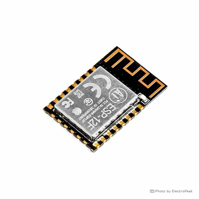
Ai Thinker ESP-12F ESP8266 WiFi Module
$1.9500
In stock
SKU
COM-03-063
Volume discounts:
- +50 4 % $1.8800
- +100 6 % $1.8400
- +300 8 % $1.8000
- +500 9 % $1.7700
- +1000 11 % $1.7300
Product Variations:
-
 ESP-12F ESP8266 Wi-Fi Module
COM-03-023 - Ai Thinker ESP-12F ESP8266 WiFi Module
COM-03-063 - ESP-12E ESP8266 Wi-Fi Module
COM-03-019 - ESP-07 ESP8266 Wi-Fi Module - IPX Antenna
COM-03-053 - ESP-12N ESP8266 Wi-Fi Development Board
COM-03-038 - Ai Thinker ESP-12S ESP8266 WiFi Module
COM-03-061 - ESP-07S ESP8266 Wi-Fi Module
COM-03-054 - ESP-12S ESP8266 Wi-Fi Module
COM-03-046


Add an Accessory:
- ESP-01/ESP12/ESP32 Universal Downloader Burning Fixture Test Board Programmer$4.9500
- NodeMCU LUA ESP8266 12E/12F Wi-Fi Development Board$1.9500


View more


Ships in 2-3 business days, then:
Free delivery in 12-15 days by Tracked Economic Shipping on orders over $100.
Free delivery in 7-10 days by Express Shipping on orders over $300.
More shipping info

Shop with confidence Learn More
 Ai Thinker ESP-12S ESP8266 WiFi Module Previous
ESP-12F WiFi Module Review
The Ai Thinker ESP-12F ESP8266 WiFi Module is a compact bare wireless module for IoT development and custom embedded hardware. Built around the 32-bit ESP8266 processor with a four-layer board design, it supports wireless communication, sensor links, and network connectivity over 2.4 GHz WiFi. This is a bare 3.3 V surface-mount module, not a development board with onboard USB or voltage regulation, so it suits designers building dedicated PCBs or prototyping with external serial and power hardware.
For projects maintaining existing layouts, the module is compatible with version 12E hardware footprints. PCB designers should still verify pad dimensions and RF clearances before substituting modules in production boards. For another ESP-12F module listing, or to compare other ESP8266 WiFi modules, the family includes several packaging and form-factor options.
Specifications of Ai Thinker ESP-12F ESP8266 WiFi Module
- Input voltage: 3 to 3.6 V DC
- Operating temperature: -40 to 125 °C
- Weight: 1.72 g
- Dimensions: 24 x 16 x 3 mm
- Clock frequency: 80 MHz
- Operating current: 80 mA
- Impedance: 50 ohm
- Flash memory: 4 MB
- Network standard: 802.11 b/g/n
- Standards: FCC / CE / TELEC
- WiFi modes: STA/AP/STA
- WiFi modes: STA/AP/STA+AP
- 802.11b/g/n Wi-Fi SOC
- Integrated Tensilica L106 ultra-low-power 32-bit micro MCU
- MCU frequency: 80 MHz
- MCU frequency: 160 MHz
- Built-in 1-ch 10 bit high precision ADC
- Supports UART/GPIO/ADC/PWM/I2C
- Package: SMD22
- Integrated Wi-Fi MAC/BB/RF/PA/LNA
- Deep sleep current: as low as 20uA
- UART baudrate: up to 4Mbps
- Embedded Lwip protocol stack
- Supports Smart Config (APP) / AirKiss (WeChat)
- Supports UART local firmware upgrade
- Supports remote firmware upgrade (FOTA)
- Supports secondary development
- Integrated Windows / Linux environment
ESP-12F Specifications Explained
The published specifications have direct implications for hardware design. Understanding them helps prevent layout mistakes and component mismatches during real-world circuit integration.
| Specification | Published Value | Why It Matters for Your Design |
|---|---|---|
| Flash Memory | 4 MB | This is SPI non-volatile flash storage for firmware binaries, file systems (such as LittleFS), and over-the-air (FOTA) update partitions. It is not working RAM. |
| Network Standard | 802.11 b/g/n | Operates strictly on the 2.4 GHz wireless band. It cannot connect to 5 GHz-only wireless networks or routers operating without a 2.4 GHz SSID. |
| WiFi Operating Modes | STA / AP / STA+AP | The module can act as a network client (Station), an access point hosting its own local network, or concurrently bridge both modes for device provisioning. |
| Package & Size | SMD22 (24 x 16 x 3 mm) | Castellated edge pads require surface-mount soldering onto a custom PCB or connection via a breakout board. It cannot plug directly into standard breadboards. |
| MCU Frequency | 80 MHz / 160 MHz | The Tensilica L106 32-bit core defaults to 80 MHz to conserve power but can run at 160 MHz in software when handling heavier tasks such as cryptographic handshakes. |
| Peripheral Interfaces | UART, GPIO, ADC, PWM, I2C | Provides flexible peripheral connectivity, though I2C is implemented in software and several exposed GPIO pins serve hardware strapping or internal flash functions. |
| Operating Current | 80 mA | Reflects average baseline operating current under standard processing, not peak RF transmission spikes which demand a more robust power supply design. |
| Deep Sleep Current | As low as 20uA | Enables intermittent battery-powered sensor nodes that wake periodically, transmit data, and return to sleep. Total project standby current depends on surrounding external components. |
| Antenna Type | Integrated PCB trace | Eliminates the cost of an external antenna and pigtail, but requires careful host-board clearance free from ground planes, copper pours, or metal enclosures. |
For simpler serial data-transfer applications with lower memory requirements, the ESP-01 (8 Mbit Flash) is a compact serial-to-WiFi alternative with 1 MB of flash and fewer exposed pins. During early ESP-12F prototyping, an ESP-12 proto adapter makes breadboard wiring and breakout access easier.
ESP-12F 3.3V Power, Boot Pins, and Programming
The ESP-12F needs specific electrical conditions and hardware states to boot and flash reliably. It operates from an input voltage range of 3 to 3.6 V DC. It does not tolerate 5 V power or 5 V logic levels; applying 5 V to VCC or directly to any GPIO or UART line will damage the silicon. Although the average operating current is listed at 80 mA, RF transmissions create brief high-current pulses. Your 3.3 V regulator must handle these dynamic demands, with adequate decoupling capacitors placed close to the module pins to prevent brownout resets.
The bare module has no USB interface, so serial programming requires an external USB-to-serial adapter. Connect module TX to programmer RX, module RX to programmer TX, and tie programmer ground directly to module ground. You can program it with a CH340G USB to TTL converter or a CP2102 USB to TTL UART serial converter module, provided the adapter is verified to output 3.3 V logic signals.
| Pin Name | Required Level for Normal Run | Required Level for Flashing / Bootloader | Hardware Wiring Rule |
|---|---|---|---|
| EN (CH_PD) | High (3.3 V) | High (3.3 V) | Pull high via resistor (e.g. 10k) to enable chip operation. |
| RST | High (3.3 V) | High (3.3 V) | Active-low reset. Pull high; pull briefly to ground to reset the module. |
| GPIO0 | High (3.3 V) | Low (GND) | Boot strapping pin. Must be held low during reset to enter UART flash mode. |
| GPIO2 | High (3.3 V) | High (3.3 V) | Must remain high during boot. Avoid pulling low with heavy loads. |
| GPIO15 | Low (GND) | Low (GND) | Must be pulled low to ground via resistor (e.g. 10k) for both boot modes. |
The module supports secondary development and Arduino-based setup. You can flash firmware directly with the Arduino IDE and the ESP8266 board package installed, or upload pre-compiled binaries through esptool. Although AT command support is listed, the installed factory firmware build and default serial baud rate can vary. For complete software-tool and core-library setup instructions, see this guide to ESP8266 Arduino IDE setup. To avoid bare-wire boot straps and manual UART converters, a USB-equipped development-board approach provides onboard USB-to-serial conversion and automated flashing circuitry on a breadboard-friendly layout.
ESP-12F Limitations and Buyer Mistakes
Review the ESP-12F trade-offs before purchase to confirm that it fits your physical layout, processing requirements, and manufacturing workflow.
- Restricted Usable GPIOs: Multiple GPIO pads are exposed on the castellated edges, but the practical pin count is lower than it appears. GPIO0, GPIO2, and GPIO15 are hardware boot straps; sensors or pull resistors that force these pins into invalid startup states will prevent the module from booting. GPIO6 through GPIO11 connect directly to internal SPI flash memory and cannot be used for general I/O. Consult this ESP8266 GPIO and boot-pin reference to map safe general-purpose pins.
- Analog Input Voltage Limits: The onboard 10-bit ADC has an input range restricted to roughly 0 to 1.0 V on the bare ESP8266 core. Connecting standard 3.3 V or 5 V analog signals directly to the ADC pin will saturate or damage the input; a passive voltage divider or external scaling circuit is required.
- Antenna Placement Constraints: The integrated meandering PCB trace antenna needs an open keep-out zone. Ground planes, copper traces, metal enclosures, or battery packs placed directly beneath or alongside the antenna end will severely degrade RF signal strength. While the listing notes improved antenna performance compared to the older ESP-12E, no controlled laboratory range data is provided, so range must be validated inside your specific enclosure. For a project inside a metal or shielded box, an external antenna option such as the ESP-07 with an IPX socket is necessary.
- No Onboard USB or Plug-In Headers: Direct prototyping on standard 2.54 mm pitch breadboards is impossible without soldering header wires or mounting the module to a carrier breakout board.
- Temperature Rating Variations: Website specifications list an operating temperature range of -40 to 125 °C, though some generic family datasheets state -20 to 85 °C. Industrial and harsh-environment projects should verify the exact operational limits of current production batches.
- Regulatory Scope: Although the module lists FCC, CE, and TELEC compliance marks, modular certification does not automatically clear a finished commercial product. System builders remain responsible for enclosure shielding, labeling, host emissions testing, and regional conformity.
ESP-12F WiFi Module Uses and Alternatives
The compact form factor, integrated PCB antenna, and low sleep consumption suit dedicated, low-cost wireless hardware. Common applications include:
- Compact WiFi Sensor Nodes: Measure temperature, humidity, or ambient light in remote locations, then transmit readings over MQTT, HTTP, or TCP/IP before entering deep sleep. Confirmed open-source implementations such as the AirWolf air-quality detector use the ESP-12F with 32 Mbit (4 MB) flash to manage sensing and network connectivity.
- Custom Home Automation Hardware: Build integrated smart relays, custom light switches, and discrete actuator controllers on custom PCBs.
- Carrier-Board Projects: Use the module as the core compute and communications daughterboard for projects such as the QDEV-8266, keeping the core radio modular while simplifying mainboard assembly.
Across the wider ESP8266 WiFi modules catalog, project requirements can call for different hardware paths:
- Minimal Serial Bridges: For simple microcontroller-to-cloud data bridging that only requires a TX/RX serial channel, the ESP-01 (8 Mbit Flash) offers a smaller package with 1 MB flash and fewer external pins.
- Challenging RF Environments: Devices housed in metal cabinets, or environments requiring directional antennas, can use the ESP-07 with IPX connector for an external antenna connection that routes signals outside the chassis.
- Dual-Wireless and High I/O Projects: Applications requiring Bluetooth/BLE communication, dual processing cores, or dozens of unrestricted digital pins call for an adjacent platform such as the WiFi and Bluetooth development-board alternative, which delivers 38 digital I/O lines and 240 MHz dual-core performance.
ESP-12F Accessories and Setup
The bare ESP-12F has no breakout pins, power regulation, or communication cables, so supporting bench hardware is required before you can get started.
Required Accessories
- Mounting / Breakout Adapter: The ESP-12 proto adapter routes the SMD22 castellated pads to standard 2.54 mm spacing for secure breadboard placement.
- Serial Programmer: A 3.3 V USB interface, such as the CH340G USB to TTL converter or CP2102 USB to TTL UART serial converter module, is essential for terminal communication and firmware uploads.
- Regulated 3.3 V Power Supply: Use a dedicated 3.3 V source capable of supplying transient RF peaks without voltage sag.
- Boot Circuit Components: Resistors establish default high and low states on EN, RST, GPIO0, GPIO2, and GPIO15.
Recommended Prototyping Gear
- Breadboard: An MB-102 breadboard provides a stable platform for the adapter and peripheral wiring.
- Interconnects: Use jumper wires to bridge serial signals, strapping pins, and power rails.
- Bench Power Module: A dedicated breadboard power supply provides verified 3.3 V rails with sufficient current capability.
- Decoupling Capacitors: Place ceramic capacitors (100 nF and 10 uF) across VCC and GND directly at the module pads.
Setup and Verification Sequence
- Solder the ESP-12F module securely onto a compatible proto adapter or test PCB.
- Connect a clean 3.3 V DC power supply to VCC and GND.
- Pull EN (CH_PD) and RST high to 3.3 V through 10k resistors. Pull GPIO15 low to GND through a 10k resistor. Ensure GPIO2 is pulled high.
- Connect the USB-to-serial adapter: Adapter TX to ESP-12F RX, Adapter RX to ESP-12F TX, and common GND.
- For normal boot, leave GPIO0 pulled high. Open a serial terminal at 115200 baud to monitor output.
- To flash firmware, pull GPIO0 to GND, cycle the RST pin low momentarily, and use the ESP8266 Arduino Core or esptool to upload code. Return GPIO0 high after flashing.
ESP-12F WiFi Module FAQ and Buying Checklist
Frequently Asked Questions
Is the Ai Thinker ESP-12F a complete ESP8266 development board?
No. This is a bare SMD22 surface-mount module. It has no USB port, 5 V regulator, tactile reset buttons, or breadboard headers, so external circuitry is required for operation.
Can the ESP-12F connect directly to a 5 V supply or 5 V UART signals?
No. The module requires a regulated input voltage between 3 and 3.6 V DC. Applying 5 V power or unshifted 5 V logic levels to GPIO and serial pins risks destroying the module.
Does the ESP-12F have USB programming built in?
No. The module does not include a USB interface. Use an external 3.3 V USB-to-serial adapter connected to the UART pins to flash code or monitor serial output.
Can I use the ESP-12F with the Arduino IDE?
Yes. The module is compatible with the Arduino IDE through the community ESP8266 board core. You still need an external USB-to-serial converter and correct boot pin states during upload.
Does the ESP-12F support 5 GHz WiFi?
No. The integrated radio operates strictly on 802.11 b/g/n networks at 2.4 GHz. It cannot communicate with 5 GHz-only wireless access points.
Is the 4 MB specification RAM?
No. The 4 MB rating designates external SPI flash memory for executable program storage and filesystems. It is not operating RAM.
How do I put the ESP-12F into programming mode?
Hold GPIO0 low (grounded) while pulsing the RST pin low. Ensure GPIO15 remains pulled low and GPIO2 remains pulled high during this power or reset transition.
Why does my ESP-12F reset continuously or fail to respond on UART?
Continuous resets are caused by inadequate 3.3 V power supply current during RF initialization, floating EN or RST pins, missing ground connections between the module and programmer, or reversed TX and RX lines.
Can I connect a 3.3 V analog sensor directly to the ESP-12F ADC pin?
No. The bare ESP8266 ADC input pin is rated for roughly 0 to 1.0 V. A 3.3 V input requires an external voltage divider to step the signal down into the safe 1.0 V operating range.
Can I replace an older ESP-12E with this ESP-12F module?
Yes, the listing notes version 12E compatibility, and the pinouts match. However, when maintaining older, sensitive layouts that must preserve the exact verified RF footprint, sourcing an existing ESP-12E PCB compatibility module ensures 100% matched trace geometry. Modules designated ESP-12S feature internal pull resistors and a different pin breakout, so they are not direct drop-in replacements.
Does the 20uA deep-sleep figure equal total battery current draw?
No. The 20uA specification applies to the bare module in deep sleep. The quiescent current of external voltage regulators, power LEDs, pull-up resistors, and connected sensors determines actual standby battery draw.
Do module FCC / CE / TELEC ratings automatically certify my finished product?
No. Modular certification covers the bare radio module under specific operating conditions. Finished commercial products require separate testing for enclosures, power supplies, unintended emissions, and regional labeling.
Purchase Decision Summary
- Ideal for: Experienced embedded hardware designers creating custom 3.3 V IoT PCBs, engineers building low-cost 2.4 GHz sensor nodes, and developers comfortable with SMD soldering, boot-strap management, and external UART tools.
- Maybe for: Prototypers willing to use breadboard breakout adapters, external USB-to-TTL converters, and dedicated 3.3 V bench power supplies.
- Avoid if: You need a plug-and-play USB development board, direct 5 V power tolerance, 5 GHz WiFi, onboard Bluetooth/BLE, or multiple unrestricted GPIO lines.
Buying Checklist
- Confirm your project calls for a bare SMD module rather than a development board with onboard USB.
- Confirm you have a regulated 3.3 V power supply capable of handling peak WiFi current spikes.
- Verify your serial programmer outputs 3.3 V logic levels to avoid damaging the UART interface.
- Plan your PCB layout or procure a breakout adapter to handle the SMD22 physical package.
- Confirm you have external resistors ready to establish proper boot levels on EN, RST, GPIO0, GPIO2, and GPIO15.
- Verify your network infrastructure operates on the 2.4 GHz band.
- Ensure your analog inputs include voltage dividers to match the bare module's 0 to 1.0 V ADC limit.
- Ensure the host PCB and enclosure leave open clearance around the integrated PCB antenna.
| MCU/SoC | ESP8266 |
|---|---|
| Product Family | ESP8266 |
| Architecture | Tensilica L106 32-bit |
| CPU Cores | 1 |
| Clock Speed (MHz) | 80 MHz |
| Flash | 4 MB |
| SRAM | 160 KB |
| EEPROM | No |
| GPIO Pins | 11 |
| SPI interface Pins | 1 |
| I2C interface Pins | 1 |
| UART interface Pins | 1 |
| USB Ports | No |
| CAN Bus Support | No |
| Ethernet Support | No |
| ADC Channels | 1 |
| DAC Channels | No |
| PWM Channels | 8 |
| Operating Voltage (V) | 3.0V - 3.6V DC |
| GPIO Voltage (V) | 3.3V |
| GPIO Current (mA) | 12 mA |
| Active Current (mA) | 80 mA |
| Sleep Current (µA) | 20 uA |
| Wireless | WiFi |
| Form Factor | 24x16x3 mm |
| IDE Support | Arduino IDE, Lua, Espressif SDK |
| Weight (g) | 1.72g |
| Input Voltage (V) | 3.0V - 3.6V |
| Antenna Type | Internal Antenna |
| Bluetooth Ver. | No |
| Operating Temp (°C) | -40 to +125 °C |
Write Your Own Review

Please complete your information below to login.
Sign In
Create New Account