
Product added to cart

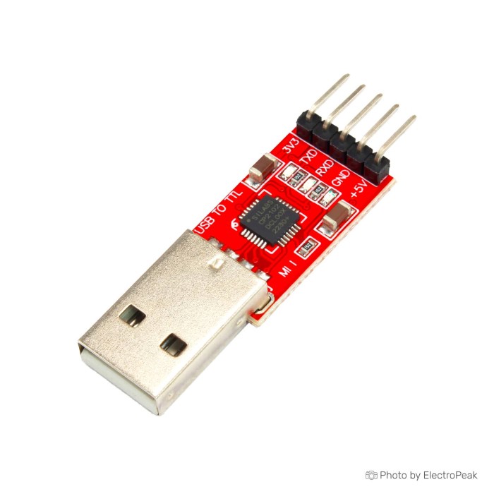
CP2102 USB to TTL UART Serial Convertor Module
$1.2700
In stock
SKU
COM-05-015
Volume discounts:
- +50 5 % $1.2100
- +100 7 % $1.1800
- +300 10 % $1.1400
- +500 13 % $1.1100
- +1000 15 % $1.0800
Ships in 2-3 business days, then:
Free delivery in 12-15 days by Tracked Economic Shipping on orders over $100.
Free delivery in 7-10 days by Express Shipping on orders over $300.
More shipping info

Shop with confidence Learn More
 USB to Mini USB Converter Cable (for Arduino Nano) Previous
CP2102 USB to TTL Module Review
The CP2102 USB to TTL UART Serial Convertor Module bridges a standard computer USB port to logic-level serial devices. Built around the Silicon Labs CP2102 controller, it provides a direct way to communicate with microcontrollers, configure serial sensors, and read embedded console logs over basic transmit and receive lines. It suits general-purpose serial data exchange, basic prototyping, and terminal monitoring on compatible hardware.
This module is designed for non-inverted logic-level UART communication. Projects requiring true RS-232 line voltages, RS-485 differential signals, galvanically isolated data lines, or verified 5 V UART signaling need dedicated hardware rather than a direct connection to this board. Although it breaks out power connections, it is not engineered as a high-current power supply for demanding radio modules. For projects with different interface requirements, the broader range of adapters and converters can help identify the proper transceiver hardware.
Specifications of CP2102 USB to TTL UART Serial Convertor Module
- Supporting various OS: Windows (XP to 10, both 32&64 bit), Mac OS 9/X, Linux, Android
- Chip: CP2102 USB to UART bridge chip
- USB Compatibility: USB 2.0 Full-Speed (12 Mbps) support
- UART Communication: Provides TX and RX pins for UART communication
- Voltage Levels: supports both 3.3V and 5V logic levels
- Baud Rate: 300bps ~1Mbps
- Working temperature: -40°C ~ 85°C.
- Dimensions:45mm x 14mm
CP2102 USB to TTL Module Specifications Explained
Knowing how the technical parameters translate to real-world use helps prevent configuration errors and hardware mismatches during development.
| Specification | Published Value | Why It Matters in Practice |
|---|---|---|
| USB Interface | USB 2.0 Full-Speed (12 Mbps) | Indicates the signaling speed of the host USB connection, not the serial data rate. The CP2102 handles USB packetization internally and presents itself to the operating system as a standard virtual COM port. |
| UART Baud Rate | 300 bps to 1 Mbps | Defines the transmission speeds available for serial transfers. Standard CP2102 devices operate reliably across standard baud rates up to 921,600 bps. The upper 1 Mbps limit reflects theoretical interface capabilities and should not be treated as a guaranteed continuous throughput on every operating system. |
| UART Pins | TXD and RXD | Provides core serial data transmission and reception. Handshake lines such as DTR, RTS, or CTS are not part of the standard breakout on this board, meaning hardware flow control is unavailable. |
| Logic Voltage | Supports 3.3V and 5V logic levels | The CP2102 core operates from an internal 3.3 V regulator with 5 V tolerant I/O pins. While inputs can tolerate 5 V signals, output signals originate from the 3.3 V domain unless dedicated external bidirectional shifting circuitry is added to the board. |
| Operating Temperature | -40°C to 85°C | Represents the industrial-grade thermal operating limits of the CP2102 integrated circuit. Overall module performance under extreme temperatures depends on the supporting passive components on the PCB. |
| Physical Dimensions | 45 mm x 14 mm | Offers a slim footprint suited for compact breadboards and enclosure breakouts. Note that published dimensions generally reflect the raw circuit board length and width; connector protrusion and pin headers require additional clearance. |
Where wider timing granularity or specific baud rates are required, a USB-to-TTL adapter with a different listed baud range, such as the PL2303 converter, covers communication ranges from 70 bps up to 12 Mbps depending on host driver support.
CP2102 USB to TTL Module Compatibility
Successful communication depends on matching signaling protocols, making clean electrical connections, and loading the appropriate system drivers. The module functions as a serial bridge, so both the host computer and target microcontroller must use asynchronous serial protocol with matching data parameters: baud rate, data bits, parity, and stop bits.
| System Layer | Requirements & Support | Key Considerations |
|---|---|---|
| Host Operating Systems | Windows (XP through 10, 32/64-bit), macOS, Linux, Android | Requires Silicon Labs CP210x Virtual COM Port (VCP) drivers. Many Linux distributions and macOS versions include native kernel support, while Windows systems may require downloading current drivers directly from Silicon Labs. |
| Electrical Signaling | Logic-level UART only | Outputs non-inverted serial data. It cannot connect directly to RS-232 serial ports (found on legacy industrial hardware), which use negative and positive swings between ±3 V and ±15 V. |
| Target Wiring | Crossed TX/RX and Common Ground | Module TXD connects to target RXD; module RXD connects to target TXD. A common GND connection between the module and the target board is mandatory for signal reference. |
| Power Rails | 5V and 3V3 power pins | The 5V pin connects directly to the USB host supply bus. The 3V3 pin outputs power from the CP2102 on-chip regulator, intended only for very light auxiliary logic pull-ups. |
For bench wiring, flexible jumper wires for UART connections make dependable pin-to-pin links between the header pins and target microcontrollers easier. Atmel microcontrollers without a serial bootloader require a different interface: serial UART conversion is not suitable, and dedicated AVR ISP programming hardware is needed to write firmware via SPI. For other interface requirements, browse the full selection of adapters and converters.
CP2102 USB to TTL Module Limitations
The CP2102 bridge is dependable for continuous serial transmission, but this generic module format has several critical constraints to account for during system design.
The module is not an isolated or high-current bench power supply. Its onboard 3V3 pin originates directly from the CP2102 internal regulator. In the Silicon Labs IC design, this regulator is intended primarily to power the chip's internal core and modest auxiliary circuitry, rated at roughly 100 mA total capacity. Attempting to power an ESP8266, ESP32, or high-power cellular module directly from this 3V3 pin will cause voltage drops, brownouts, or target reset loops during Wi-Fi transmission bursts. High-current targets must always use an external regulated supply with grounds tied together.
The 5V power pin exposes raw USB bus power. No onboard polyfuse, reverse-polarity diode, or back-feed protection is documented for this board. Connecting an externally powered 5 V system to this pin while it is plugged into a host computer risks back-powering the host machine's USB port, which can trigger motherboard port protection or cause hardware instability.
Hardware control pins are absent from this pinout. Standard automatic reset circuits on development boards use DTR (Data Terminal Ready) and RTS (Request to Send) pins to toggle reset and bootloader modes automatically during code compilation and upload. Because this module exposes only TXD, RXD, GND, 5V, and 3V3, automated flashing cannot occur without manual button presses on the target board.
Onboard level-shifting ICs do not actively manage signal conversion. Although the CP2102 inputs tolerate 5 V logic, its transmit output high-level remains near 3.3 V. While 3.3 V is high enough to register as a logic high on most 5 V TTL microcontrollers, which typically require 2.0 V minimum for logic high, noisy environments or strict CMOS thresholds may experience dropped bits without a dedicated level shifter.
For complex development setups that require reliable automated reset sequences and substantial target power, dual-channel ESP programming hardware with high-current 3.3V regulation provides dedicated power circuitry and coordinated control lines on USB-C.
CP2102 USB to TTL Module for ESP and Arduino Serial Programming
Microcontroller development boards frequently use UART for firmware uploads and real-time debugging. The CP2102 module can interface successfully with these boards when the flashing procedure is handled correctly.
For ESP8266 or ESP32 programming over basic serial connections, the absence of DTR and RTS signals means the developer must trigger bootloader mode manually. Pull GPIO0 to ground, pull the Reset pin to ground momentarily, then release the Reset pin while keeping GPIO0 grounded. Once the chip enters the ROM serial bootloader, flashing software such as esptool can push the binary over TX and RX lines. After the upload finishes, GPIO0 must be disconnected from ground before resetting the chip into normal execution mode.
Dedicated jumper wires for UART connections simplify these manual bench connections. For socketed mini-boards, a dedicated ESP-01/ESP-01S downloader integrates the correct bootmode transistors and an onboard socket, eliminating breadboard jumpers entirely.
CP2102 USB to TTL Alternatives
The right serial converter depends on the target chip, protocol requirements, and whether automated reset control is necessary.
| Product | Primary Use Case | Differentiating Features |
|---|---|---|
| CP2102 USB to TTL Module (This board) | General logic-level serial communication and console monitoring | Silicon Labs architecture, compact 5-pin breakout, reliable driver ecosystem. |
| CH340G USB-to-TTL alternative | General serial debugging and basic MCU programming | CH340G bridge chip, 6-pin breakout board (30 mm x 16 mm), integrated male USB-A plug. |
| PL2303 USB to TTL Converter | Serial data links requiring wide baud rate selection | PL2303 bridge chip, thumb-drive form factor (50 mm x 14 mm), listed rates from 70 bps to 12 Mbps. |
| Dual Serial USB Module with GD32F150G8 | Automated flashing for ESP8266, ESP32, and K210 devices | Dual serial channels, USB-C interface, onboard Cortex-M3 controller, high-current 3.3 V buck regulator. |
| ESP-01/01S Downloader with CH340C | Zero-wire programming of ESP-01 modules | Direct plug-in socket, automatic boot-mode circuitry using CH340C, compact USB stick format. |
| USBasp AVR ISP Programmer | Direct low-level flashing of AVR/ATtiny microcontrollers | Uses SPI in-system programming rather than UART; writes bootloaders, fuses, and flash memory directly. |
| CH341A EEPROM/Flash BIOS Programmer | Direct memory chip recovery and flashing | Designed specifically for 24-series I2C EEPROMs and 25-series SPI flash chips rather than serial stream monitoring. |
CP2102 USB to TTL Module Setup and FAQ
Use this sequence to confirm that the adapter functions correctly before wiring it into a project:
- Check Pin Labels: Inspect the silk-screen markings on the module header. Standard pins are 5V, GND, RXD, TXD, and 3V3.
- Install Driver: Connect the module to a host computer USB port. If the operating system does not automatically enumerate the device, download and install the official CP210x VCP driver package from Silicon Labs.
- Verify Port Enumeration: Open Device Manager (Windows), System Information (macOS), or run
dmesg | grep tty(Linux) to confirm that a new serial port (e.g., COM3, /dev/ttyUSB0, or /dev/cu.SLAB_USBtoUART) appears. - Wire to Target: Disconnect the module from USB. Connect GND to the target board's GND. Connect module TXD to target RXD, and module RXD to target TXD. For bench testing, a breadboard setup for UART testing keeps jumper connections secure.
- Configure Terminal Software: Reconnect USB, launch your preferred serial monitor (PuTTY, Tera Term, screen, or the Arduino Serial Monitor), select the assigned COM port, and set matching baud rate, data bit, parity, and stop bit configurations.
Memory chips require a different approach than microcontrollers. Standard UART adapters cannot read parallel or SPI flash structures directly; use a dedicated solution for EEPROM and SPI flash programming instead. For broader cabling and conversion requirements, consult our catalog of adapters and converters.
Frequently Asked Questions
Is this a USB-to-RS-232 adapter?
No. This module outputs logic-level UART signals and cannot communicate directly with true RS-232 equipment. RS-232 standards use bipolar signaling between ±3 V and ±15 V, which will permanently damage a directly connected TTL serial module. Legacy DB9 or industrial RS-232 systems require an external RS-232 transceiver IC.
How do I wire a CP2102 USB to TTL module?
Cross the data lines and share a common ground. Connect the module TXD to the target RXD, the module RXD to the target TXD, and the module GND to the target GND. The data lines must be crossed because the transmitter on one side must speak to the receiver on the other.
Does this CP2102 module work with ESP8266 or ESP32?
Yes, it functions as a serial link for ESP devices, but flashing requires manual bootloader entry. Since the module does not break out DTR and RTS lines for auto-reset, you must manually pull GPIO0 to ground during boot to initiate flashing, and you should provide an independent 3.3 V supply to meet the ESP's radio current demands.
Can the 3.3V pin power my microcontroller?
The 3.3V pin is limited to low-current auxiliary tasks and should not power microcontrollers with active transceivers. The CP2102 internal regulator is designed for minor loads; powering an ESP32, Wi-Fi module, or radio transceiver from this pin will lead to brownouts and erratic behavior.
Can I use this with 5V Arduino UART pins?
Yes, the CP2102 inputs are 5 V tolerant, allowing direct connection from a 5 V microcontroller's TX line to the module's RXD pin. However, the module's TXD output sends a 3.3 V high signal, which falls within standard 5 V TTL input detection thresholds but may have reduced noise margins on strictly defined 5 V CMOS inputs.
Why is my CP2102 COM port not showing?
A missing COM port points to a missing driver, a charge-only USB cable, or a loose connection. Verify that the cable supports data transfer, download the current CP210x VCP driver directly from Silicon Labs, and check whether the device appears under USB controllers or ports in your system device tree.
Is 1 Mbps guaranteed?
No. 1 Mbps is the theoretical maximum baud limit of the CP2102 hardware architecture, not a guaranteed sustained transfer rate. Silicon Labs fully documents standard baud rates through 921,600 bps; speeds approaching 1 Mbps depend on operating system latency, terminal buffer handling, and cable length.
Does this module automatically reset and upload to every ESP or Arduino board?
No, this module does not support automatic reset because it does not break out DTR or RTS handshake pins. Boards programmed through Arduino IDE or ESP tools that rely on auto-reset will time out unless the user manually toggles the reset and boot pins into download mode at the start of the upload sequence.
Are jumper wires or a USB cable included?
No accessories are confirmed as included in the package. You need a suitable USB data cable matching the board's connector and female-to-male or female-to-female jumper wires to connect the header pins to your target device.
Purchase Decision Summary
| Suitability | Project Profile | Recommendation |
|---|---|---|
| Ideal For | Basic serial debugging, sensor configuration, boot-log reading, and general UART data communication. | A practical, cost-effective choice when basic TX, RX, and GND lines are all your hardware requires. |
| Maybe For | ESP8266, ESP32, and Arduino programming workflows. | Usable if you have external target power and are comfortable manually triggering bootloader and reset pins. |
| Consider Another Option If | Automated ESP flashing, high-current 3.3 V target power, RS-232 industrial voltage levels, or AVR ISP programming. | Choose a dedicated ESP flasher with DTR/RTS auto-reset, an ISP programmer, or an industrial RS-232 transceiver module. |
Buying Checklist
- Target Interface: Confirm your target device uses logic-level asynchronous UART, not RS-232 (±12 V), RS-485, CAN, I2C, or SPI.
- Handshake Pins: Verify that your project requires only TXD and RXD; this module does not provide DTR, RTS, or hardware flow control lines.
- Target Power Source: Ensure your target microcontroller has its own regulated power supply, especially if using Wi-Fi or radio modules that draw significant current.
- Baud Rate Requirements: Check that your desired baud rate falls within the supported 300 bps to 921,600 bps range.
- Cabling & Jumpers: Confirm you have female-ended jumper wires and an appropriate USB data cable ready for bench connections.
| Interface Type | USB, UART |
|---|---|
| Operating Voltage (V) | 3.3V, 5V |
| Operating Temp (°C) | -40°C to 85°C |
| Dimensions (mm) | 45mm x 14mm |
| Interface Category | USB to TTL Converter |
| Output Type | UART |
| Channels | 1-channel |
| Chipset | CP2102 |
| Voltage Range | 3.3V and 5V |
| Protocols | UART |
| Conversion Type | USB to TTL |
Write Your Own Review

Please complete your information below to login.
Sign In
Create New Account