
No — a bare Raspberry Pi has no analog inputs, so an analog joystick module needs an ADC such as MCP3008 or ADS1115, while a USB gamepad works directly over USB. That is why Pi buyers choose a USB controller for gaming and reserve raw joystick modules for MCU projects or Pi builds that already include an ADC.
Keypad & Joystic
Choose the right input type first
| Project / host | Best-fit product family | Connects as | Why it fits | Main trade-off / avoid if |
|---|---|---|---|---|
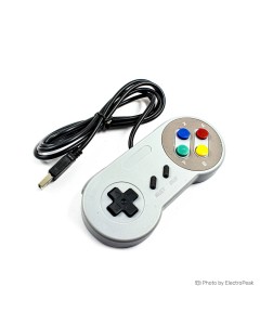
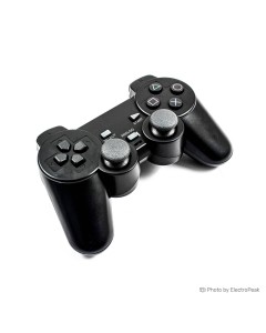
| Pi/PC retro gaming | Classic USB wired gamepad | USB HID | This SNES-style USB 2.0 controller plugs straight into Raspberry Pi or PC, has a 1.4m cable, and gives you a D-pad with 8 buttons plus L/R shoulders, Start, and Select. It is the direct path for RetroPie, RetroArch, and emulator builds. | Wired only. Avoid raw analog parts here unless you want to build and code your own controller. |
| Arduino/ESP32 numeric entry | 4x4 membrane keypad or TTP229 4x4 touch keypad | Matrix scan or TTP229 interface | Matrix keypads handle discrete key presses, so they fit PIN pads, menu systems, and code entry. The touch version keeps wiring down to about 2–3 pins when GPIO is tight. | A raw 4x4 matrix uses 8 GPIO, and touch boards need the right TTP229 code for the exact variant. |
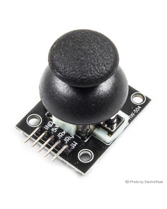
| Arduino/ESP32 analog movement | Dual-Axis XY joystick module | Analog X/Y voltages, often plus SW click on this style of joystick module | This compact 33x27mm analog joystick module fits breadboard and custom MCU builds where you want free wiring and proportional control. | A bare Raspberry Pi cannot read it directly because it has no analog inputs; you need an ADC such as MCP3008, or choose a USB gamepad instead. See how a raw joystick module is wired and read on Arduino. |
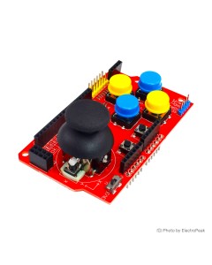
| Quick Arduino demo board | Arduino joystick shield with PS2 stick | Arduino shield form factor | This Arduino-form-factor shield combines a PS2 dual-axis joystick, 7 momentary buttons, selectable 3.3V or 5V operation, and integrated interfaces for Nokia 5110 LCD, nRF24L01, Bluetooth, and I2C. A convenient choice when the board footprint matches. | Better suited to Arduino-compatible shield layouts only; a loose module is more flexible for custom layouts or non-shield hosts. |
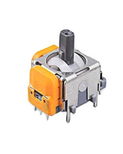
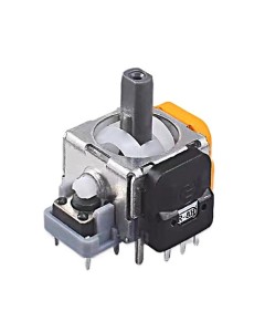
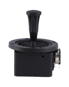
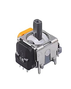
| Raw repair or panel integration | ZY-D203B 3-axis joystick potentiometer | Raw 10KΩ potentiometer element | This is a raw 10KΩ joystick potentiometer with 3-axis detection and no module PCB, so it fits repairs, custom panels, or designs that do not want a breakout board. | Not a plug-in module. You must provide your own wiring, mechanics, and signal handling. |
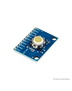
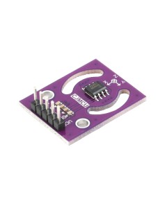
| Niche cursor or 360° control | ICSH044A Hall effect trackball module | Trackball motion sensing | This Hall effect trackball module is the specialized option when a joystick is the wrong motion style. It supports 360° motion detection, includes an internal push button selector, and has 4 built-in RGBW status LEDs. | It is a different interaction model from a thumb joystick, so avoid it if you want a familiar stick feel. |
If you are building around a Raspberry Pi board, the split is simple: USB gamepads are direct USB devices, while analog joystick modules are raw components and need code plus an ADC plan.
Keypad choice: 3x4, 4x4, flat, micro-switch, or capacitive touch
| Keypad type / example product | Keys | Typical GPIO need | Connection style | Mounting / form factor | Best fit | Main gotcha |
|---|---|---|---|---|---|---|
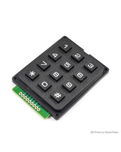
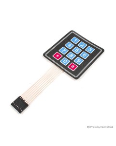
| 4x3 membrane keypad | 12 | 7 | Solder pad connection points | Membrane panel with mounting holes | Simple fixed electronics where 12 keys are enough | Requires soldering to pads |
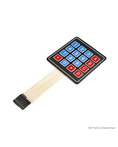
| 4x4 membrane keypad | 16 | 8 | Solder pad connection points | Membrane panel, integrated mounting holes, 70x65mm | Password entry, menu projects, extra A–D function keys | Uses one more GPIO than 3x4 and still needs soldering |
| 3x4 flat keypad | 12 | 7 | 7-pin flat connection | 0.8mm ultra-thin surface-mount style | Low-profile front panels and adhesive-style surfaces | No mounting holes; flat cable style needs more care |
| 4x4 flat keypad | 16 | 8 | Flat keypad connection | Flat 76x69mm panel | Flat 16-key password or menu surfaces | Still a matrix keypad, so pin count stays high |
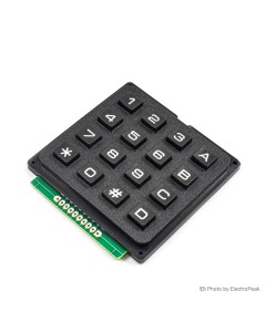
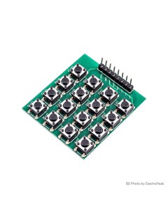
| 4x4 micro switch keypad | 16 | 8 | Male pin header | Rigid board with four 3mm mounting holes | Tactile button feel and easier header-based wiring | Non-encoded matrix, so you still scan rows and columns |
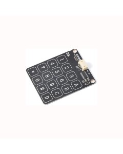
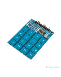
| TTP229 4x4 capacitive touch keypad | 16 | 2–3 | TTP229 interface | Touch keypad PCB with 16 touchpads | Wear-free, flat control surfaces | Verify the exact board variant and mode before buying |
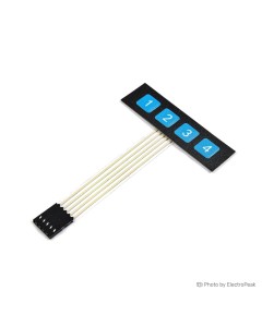
| 1x4 flat keypad | 4 | — | FPC circuit with 4-pin flat cable | Self-adhesive compact strip | Small menu adjustments and compact control surfaces | Not a full matrix keypad replacement |
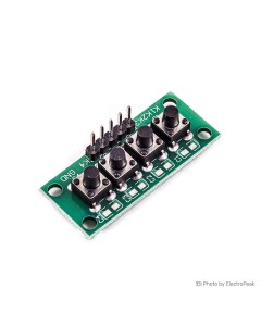
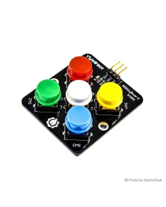
| 1x4 independent button keypad | 4 | 4 | Independent button outputs to ground | Small tactile button board | Simple direct button input with no matrix scanning | Uses one input per button |
A 3x4 matrix keypad is enough for digits plus * and #; move to 4x4 when you need A–D keys for confirm, cancel, mode, or menu shortcuts. That extra column costs one more GPIO. It matters once you also add a display, sensors, or RF modules. If your keypad project also needs a screen, check the available LCD options before you commit your pin budget.
Membrane keypad and capacitive touch solve different problems, not just different looks. Membrane is cheaper, tactile, and easier for beginners, and standard matrix scanning is already handled by the Arduino Keypad library. Capacitive touch is flat and has no moving parts, but it is pickier about power, grounding, and overlay thickness. For a standard 4x4 keypad build, this example wiring for a 4x4 matrix keypad shows the usual scan approach. If you are new to Arduino keypads, use the Keypad library, not the Keyboard library.
The XD-62B TTP229 touch keypad uses the TTP229 IC, has 16 touchpads, and includes an on-board power indicator, but you should still verify the exact variant. TTP229 boards are often confused as standard I2C. Multiple variants exist, including 2-wire serial and I2C versions, plus 8-key and 16-key modes set by jumpers.
Joystick quality and compatibility: what cheap modules can and cannot do
| Product family / example | Best for | Signal type | Voltage note | Extra controls | Main limitation |
|---|---|---|---|---|---|
| Dual-Axis XY joystick module | Breadboard control, simple robots, compact custom builds | Analog X/Y | Power at 3.3V for 3.3V boards | Commonly this class includes an SW press function | Low-cost potentiometer behavior means calibration is normal |
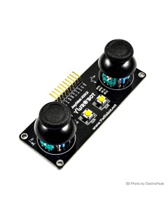
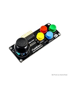
| YwRobot joystick and button module | Control panels that need one stick plus discrete buttons | One analog X/Y joystick plus digital buttons | 3.3V/5V operation | Four independent buttons with color key caps, digital pulled-up outputs | Larger and more specific than a plain joystick board |
| Arduino dual-axis joystick shield | Fast Arduino demos and handheld controller layouts | Analog joystick on shield | Selectable 3.3V or 5V | 7 momentary buttons | Locked to Arduino shield form factor |
| ZY-D203B joystick potentiometer | Repair work, custom mechanics, higher-spec analog designs | Raw 10KΩ potentiometer outputs | Depends on your own circuit design | 3-axis detection | No module PCB or ready-to-wire breakout |
| ICSH044A Hall effect trackball module | Drift-resistant motion input and 360° control | Hall effect motion sensing | — | Internal push button selector, 4 RGBW LEDs | Not a thumb joystick replacement in feel or mechanics |
Cheap joystick modules are good enough for learning and casual robot control, but they are widely considered marginal for precise RC transmitters. KY-023-class designs use low-grade 10kΩ potentiometers, so center commonly lands around 500–524 on a 10-bit ADC instead of exactly 512. On ESP32-class 12-bit reads, the same center expectation is roughly 1900–2100. That is normal center offset, not immediate proof of a bad part.
Drift, jitter, and robot creep at idle are often fixed in software with ADC averaging and a dead zone rather than by replacing the module right away. If you need the common press-down switch, KY-023 and YwRobot-style modules usually provide an SW pin that is active LOW and should be read with INPUT_PULLUP. The YwRobot joystick and button module is the better fit when the panel also needs four separate buttons, while the 33x27mm dual-axis joystick board makes more sense when space is tight. For 3.3V hosts such as ESP32 boards, powering a KY-023-type joystick at 3.3V is the safe choice; powering it at 5V and feeding 3.3V-tolerant pins risks damage. If long life matters more than lowest price, Hall effect sensor hardware is the drift-resistant upgrade. For calibration-minded builds, see what center values and axis wiring look like on a PS2-style joystick module.
Pre-purchase checks that prevent the most common wrong buys
- Confirm the host first: these are add-on input parts for a host board such as Arduino boards, not standalone devices.
- If the host is Raspberry Pi, a raw analog joystick still needs an ADC such as MCP3008 or ADS1115. If you do not want that extra hardware, choose the USB wired gamepad instead.
- Check the pin budget before ordering: a 3x4 matrix keypad needs 7 GPIO and a 4x4 needs 8, while a PCF8574 or MCP23017 can cut a raw matrix keypad down to 2 I2C pins.
- Check the connection style, not just the key count:
- The 4x3 membrane keypad and 4x4 membrane keypad use solder pad connection points.
- The 4x4 micro switch keypad uses a male pin header connection.
- Unsoldered headers or solder-pad terminations are a top cause of “nothing works” complaints.
- Do not assume a membrane keypad ribbon is pinned in row/column order. Ribbon pin order varies by manufacturer, so verify it with a multimeter continuity test.
- For TTP229 boards, verify both protocol and mode:
- A common reason only 8 keys work is an 8-key vs 16-key mode mismatch.
- Buyers also mix up serial and I2C variants.
- This how to wire and configure a TTP229 keypad correctly guide is the right reference if that is your concern.
- For RetroPie, USB gamepads usually behave best when plugged in before boot. Generic D-input-only pads may still need manual configuration or a mode switch.
FAQs on Keypad & Joystic
Will an analog joystick module work directly with Raspberry Pi?
How many pins does a matrix keypad use?
A 3x4 matrix keypad typically needs 7 GPIO, a 4x4 matrix keypad needs 8 GPIO, and a PCF8574 or MCP23017 can reduce a matrix keypad to 2 I2C pins. If your project already uses a display or several sensors, that difference matters more than the keypad price.
Why doesn’t a joystick module sit exactly at 512?
Cheap 10kΩ joystick modules commonly rest around 500–524 on a 10-bit ADC instead of exactly 512, and on ESP32-class 12-bit reads the center is roughly 1900–2100; calibration and a dead zone are normal. A small offset by itself is expected behavior on low-cost potentiometer sticks.
What’s the difference between a joystick module, a joystick shield, and a USB gamepad?
A joystick module is a raw analog X/Y input part for MCU projects, a joystick shield is that concept pre-wired onto an Arduino-form-factor board with extra buttons, and a USB gamepad is a self-contained HID controller for Pi/PC. They are not interchangeable, even if all three are used for directional input.
Is the TTP229 keypad really I2C?
Not always — TTP229 boards are not all the same, with both 2-wire serial and I2C variants in circulation, plus 8-key and 16-key modes selected by jumpers. The exact board marking and your code need to match the variant you are buying.
Do cheap USB gamepads work with RetroPie out of the box?
Usually yes if the pad is a standard HID device and is plugged in before boot, but generic D-input-only pads may need manual configuration or mode switching. That is the usual reason behind “no gamepads detected” reports on RetroPie builds.
Do I need to solder anything with these keypads and joystick boards?
Sometimes — the 4x3 and 4x4 membrane keypads use solder pad connection points, while the 4x4 micro switch keypad already has a male pin header connection. Check that before ordering, because connection style causes more frustration than the input type itself.
Glossary
- Matrix keypad
- — A keypad that shares buttons across row and column lines, which is why 12 or 16 keys can be read with 7 or 8 GPIO instead of one pin per key.
- ADC
- — An analog-to-digital converter that turns joystick voltage into numbers; Arduino boards have one, but a bare Raspberry Pi does not.
- Dead zone
- — A small ignored range around joystick center that prevents drift and robot creep when the stick is supposed to be at rest.
- INPUT_PULLUP
- — A built-in pull-up setting used on button inputs so a joystick SW pin does not float and trigger randomly.
- TTP229
- — A touch-keypad controller used on 16-key capacitive boards, with variant and mode differences that affect wiring and code choice.
- USB HID
- — The standard that lets a USB gamepad behave as a plug-and-play controller on Pi, PC, and other host systems.
- Hall effect sensor
- — A contactless position-sensing method that avoids potentiometer wear and is the drift-resistant upgrade path.
- Ribbon cable / FPC tail
- — The flat flexible connector used on many membrane and flat keypads, where pin order should be checked instead of assumed.
Please complete your information below to login.
Sign In
Create New Account