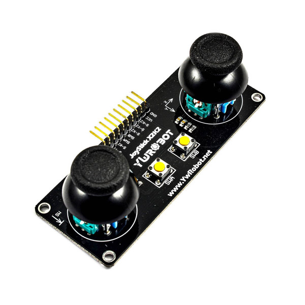
PS2 Joystick Module Features
This module consist of two joysticks and two independent buttons. The joystick is very useful in robotics. Each joystick has two potentiometers on two X and Y axes and one push button. This module has two analog outputs and one digital output. In robotics, it can be used to control moving parts and motors.
How it works
This module contain two potentiometers in both X and Y axis. As shown below, the joystick is normally in the middle, and both potentiometers provide 2.5V for each analog output. This value is converted to 512 in Arduino by analog to digital converter (ADC). For example, if we move joystick in the X axis, this value changes from 512 to 1023, and if we move it in the opposite direction, it decreases from 512 to 0. The same for Y axis.

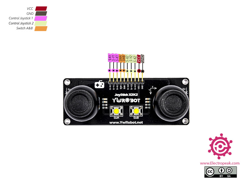
PS2 Joystick Module Pinout
This module has 10 pins:
- S-X1: Analog output pin on X-axis – joystick 1
- S-Y1: Analog output pin on Y-axis – joystick 1
- S-K1: Digital Switch Output pin – joystick 1
- S-X2: Analog output pin on X-axis – joystick 2
- S-Y2: Analog output pin on Y-axis – joystick 2
- S-K2: Digital output switch pin – joystick 2
- SWA: Separate switch A
- SWB: Separate switch B
- VCC: Module power supply
- GND: Ground
You can see the pinout of this module in the image below.
Required Materials
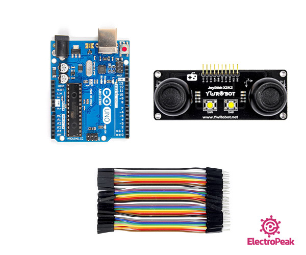
Hardware Components
Software Apps
Interfacing PS2 Joystick Module with Arduino
Step 1: Circuit
The following circuit shows how you should connect Arduino to this module. Connect wires accordingly.

Step 2: Code
Upload the following code to Arduino.
    /*
  YwRobot-PS2-Joystick-Module
  made on 16 Nov 2020
  by Amir Mohammad Shojaee @ Electropeak
  Home

*/

#define x1 A0
#define y1 A1
#define k1 2
#define swa 3

#define x2 A4
#define y2 A5
#define k2 6
#define swb 7

void setup() {
  pinMode(k1,OUTPUT);
  pinMode(k2,OUTPUT);
  pinMode(swa,OUTPUT);
  pinMode(swb,OUTPUT);

  Serial.begin(9600);
}

void loop() {
  int x1_axis=analogRead(x1);
  int y1_axis=analogRead(y1);
  int x2_axis=analogRead(x2);
  int y2_axis=analogRead(y2);

  Serial.print("x1_axis: ");
  Serial.print(x1_axis);
  Serial.print("  y1_axis: ");
  Serial.print(y1_axis);

  Serial.print("  x2_axis: ");
  Serial.print(x2_axis);
  Serial.print("  y2_axis: ");
  Serial.println(y2_axis);

  if(digitalRead(k1)==HIGH){
    Serial.println("  k1 pressed ");
    while(digitalRead(k1)==HIGH){}
  }
  if(digitalRead(swa)==HIGH){
    Serial.println("  swa pressed ");
    while(digitalRead(swa)==HIGH){}
  }
  if(digitalRead(k2)==HIGH){
    Serial.println("  k2 pressed ");
    while(digitalRead(k2)==HIGH){}
  }

  if(digitalRead(swb)==HIGH){
    Serial.println("  swb pressed ");
    while(digitalRead(swb)==HIGH){}
  }
  delay(200);
}
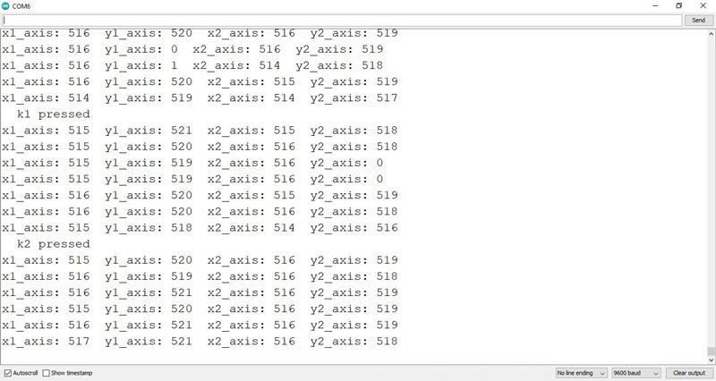
In this code you can completely check the performance of this module. The values of 4 axes X1, Y1, X2 and Y2 are shown in the Serial Monitor. You can easily change the output by moving the joysticks. By pressing each key, it will be displayed on Serial Monitor.
Look at the following image. We first move both joysticks in the opposite direction of Y-axis and then press each button.