

Overview
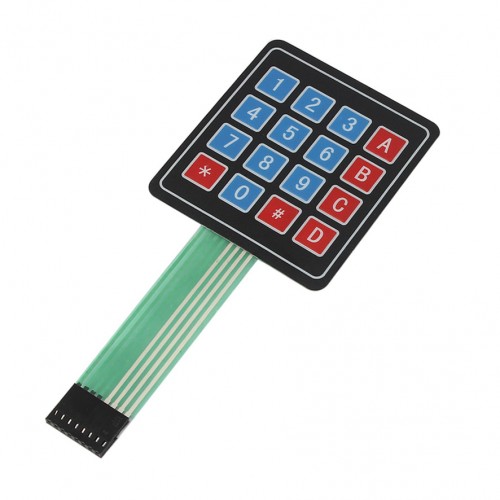
A keypad is a device that can be used to receive input data from user.
In this project, you will first learn how to interface a 4×4 keypad with Arduino, and then you will Build a simple calculator using a keypad.
What You Will Learn
- What is keypad
- Different kind of keypads
- How does keypad work
- How to interface keypad with Arduino
- How to interface keypad in different methods
- Build a calculator
How Does A Keypad Work?
Since past until now, there has been various methods to enter data into devices and systems such as buttons, audio, image, etc.
Keypad is one of the most effective methods to enter data into the system. The advantage of this method over other methods is that it is easy to use and cheap. – That’s why we see a lot of keypads around us. Like your computer keypads, which is a kind of large keypads.
The keypads are made of 2 plastic sheets that have wired lines that reach each other at the specified points and are placed on top of each other using special techniques.
Different Kind of Keypads
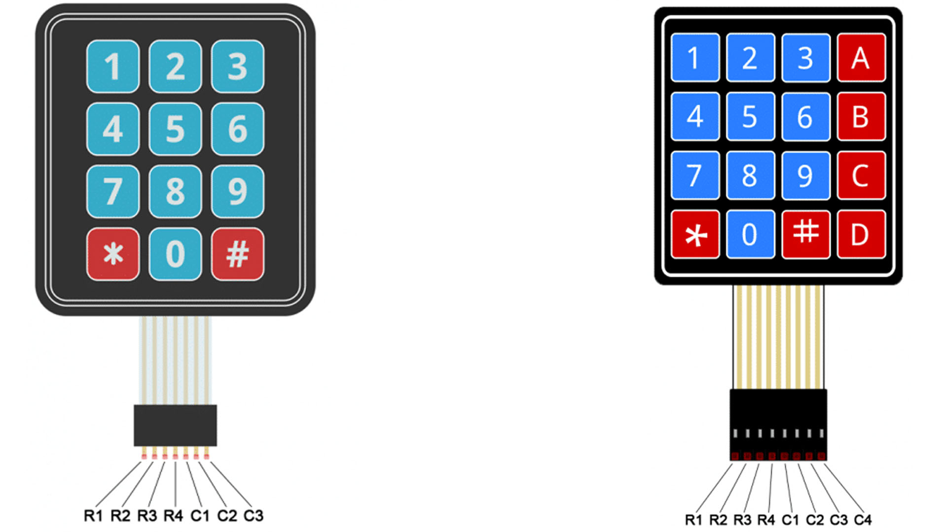
Keypads are made in various types, but the most common sizes are 5 * 4 and 4 * 4.
These numbers indicate the number of rows and columns of the keypads. For example, A 3*4 keypad has 4 rows and 3 columns.
How Does A Keypad Work?
To receive data from 12 buttons, we need to use 12 digital pins from our microcontroller (Arduino), and this means wasting a lot of pins, but using the keypad, we only need 7 digital pins. You can see how the keypad works in the animation below.
Required Materials
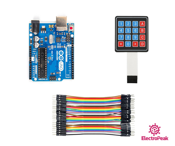
Hardware Components
Software Apps
Interfacing Keypad with Arduino
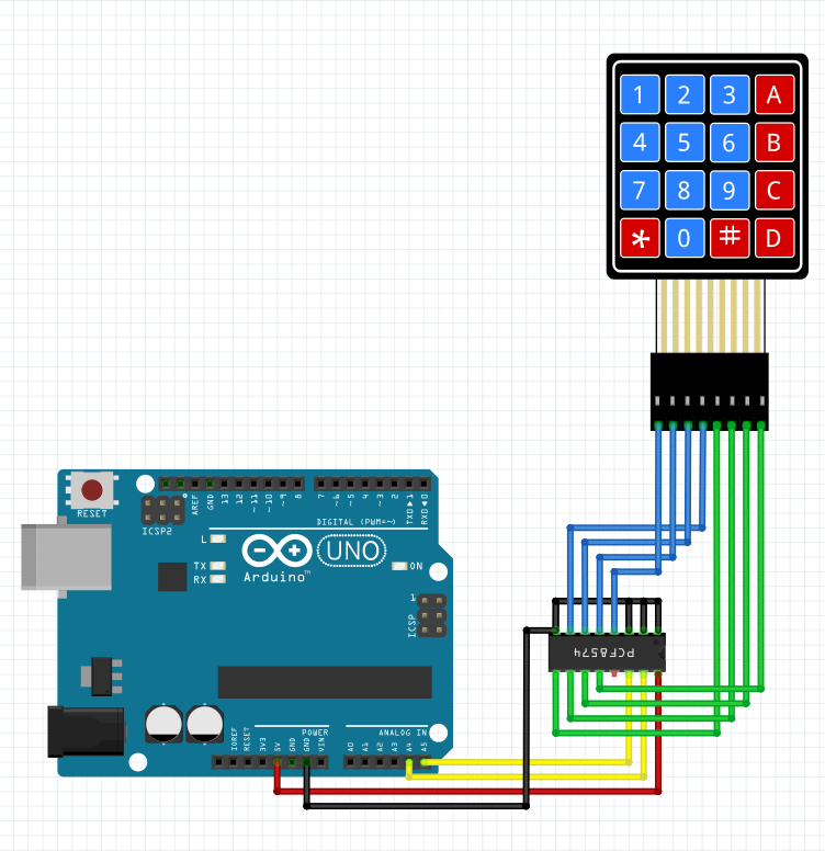
There are 4 methods in order to connect keypad to Arduino: matrix, converters, resistors and a combination of resistors and matrix.
In method 1, we have to connect all the keypad pins to Arduino.
In method 2, we use special ICs.
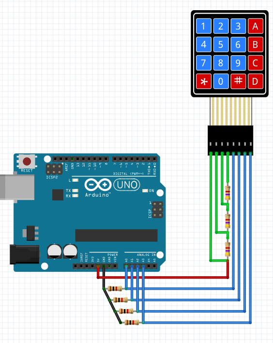
In method 3, we connect all the keypad pins together using a matrix of resistors and finally connect to the Arduino analog pin.
In method 4, which is a combination of the first and third method, we connect each column separately to the analog pin.
The pros and cons of each method is listed in the table below:
| Method 1 | Method 2 | Method 3 | Method 4 | |
|---|---|---|---|---|
| Performance speed | too high | too high | Low | Middle |
| Number of used pins | too high | Low Just 2 pin | Just 1 pin | Middle |
| Coding | Middle | Middle | Easy | Middle |
| Hardware connection | Middle | Middle | Difficult (Soldering required) | Middle |
| Cost | Low | High | Middle | Low |
Note
In this tutorial, you will learn how to interface a keypad and build a calculator using the first method.
Circuit
You can see the circuit of each method in the following images.


Code
You can download the required library from the following link.
Tip
If you need more help with installing a library on Arduino, read this tutorial: How to Install an Arduino Library
Note
/* @file CustomKeypad.pde
|| @version 1.0
|| @author Alexander Brevig
|| @contact [email protected]
||
|| @description
|| | Demonstrates changing the keypad size and key values.
|| #
*/

#include <Keypad.h>

const byte ROWS = 4; //four rows
const byte COLS = 4; //four columns
//define the cymbols on the buttons of the keypads
char hexaKeys[ROWS][COLS] = {
  {'1', '2', '3', 'A'},
  {'4', '5', '6', 'B'},
  {'7', '8', '9', 'C'},
  {'*', '0', '#', 'D'}
};
byte colPins[ROWS] = {5, 4, 3, 2}; // Pins used for the rows of the keypad
byte rowPins[COLS] = {9, 8, 7, 6}; // Pins used for the columns of the keypad

//initialize an instance of class NewKeypad
Keypad customKeypad = Keypad( BuildKeymap(hexaKeys), rowPins, colPins, ROWS, COLS);

void setup(){
  Serial.begin(9600);
}
void loop(){
  char customKey = customKeypad.getKey();

  if (customKey){
    Serial.println(customKey);
  }
}
After uploading the code, open the serial monitor and press each of the keypad buttons. You should see the number corresponding to each button. If the number corresponding to each button is not displayed, define them in the code.
How to Build a Calculator?
To build a calculator, we need a type of keypad that has all the numbers 0 to 9 and at least 5 separate keys for mathematical operators.
Circuit

Code
Upload the following code to Arduino and enjoy your calculator. Please note that the previous section must have been done properly, otherwise the code may not work.
Note
If you changed the buttons numbers in the previous section, you should apply them in this code too.
    /*
modified on 7 Jul 2020
Home
*/
#include <Keypad.h>
const byte ROWS = 4; // four rows
const byte COLS = 4; // four columns

float firstNumber = 0;
float secondNumber = 0;
float result = 0;
bool section = false;
int type = 0;

// Map the buttons to an array for the Keymap instance
char hexaKeys[ROWS][COLS] = {
  {'1', '2', '3', 'A'},
  {'4', '5', '6', 'B'},
  {'7', '8', '9', 'C'},
  {'*', '0', '#', 'D'}
};
byte colPins[ROWS] = {5, 4, 3, 2}; // Pins used for the rows of the keypad
byte rowPins[COLS] = {9, 8, 7, 6}; // Pins used for the columns of the keypad
// Initialise the Keypad
Keypad customKeypad = Keypad(BuildKeymap(hexaKeys), rowPins, colPins, ROWS, COLS);

void setup() {
  Serial.begin(9600);   // Initialise the serial monitor
}

void loop() {
  // Read the pushed button
  int button = int(customKeypad.getKey()) - 48;
  if (0 <= button && button <= 10) {
    Serial.print(button);
    if (section == false) {
      firstNumber = firstNumber * 10 + button;
    } else {
      secondNumber = secondNumber * 10 + button;
    }
  } else {
    switch (button) {
      case 17://A

        section = true;
        type = 1;
        Serial.print('+');
        break;
      case 18://///B

        section = true;
        type = 2;
        Serial.print('-');
        break;
      case 19:////C

        section = true;
        type = 3;
        Serial.print('*');
        break;
      case 20:////D

        section = true;
        type = 4;
        Serial.print('/');
        break;
      case -6:////*

        section = false;
        type = 0;
        Serial.println(' ');
        break;

      case -13://///#
        Serial.print(" = ");
        switch (type) {
          case 1:
            result = (firstNumber + secondNumber);
            break;
          case 2:
            result = (firstNumber - secondNumber);
            break;
          case 3:
            result = (firstNumber * secondNumber);
            break;
          case 4:
            result = (firstNumber / secondNumber);
            break;
        }
        type = 0;
        Serial.println(result);
        firstNumber = 0;
        secondNumber = 0;
        section = false;
        break;

    }
  }
}
Defining the number of keypad rows and columns:
const byte ROWS = 4; // four rows
const byte COLS = 4; // four columns
Specifying how cells are arranged in the keypad.
char hexaKeys[ROWS][COLS] = {
  {'1', '2', '3', 'A'},
  {'4', '5', '6', 'B'},
  {'7', '8', '9', 'C'},
  {'*', '0', '#', 'D'}
};
The Arduino pins number connected to the keypad:
byte colPins[ROWS] = {5, 4, 3, 2}; // Pins used for the rows of the keypad
byte rowPins[COLS] = {9, 8, 7, 6}; // Pins used for the columns of the keypad
Keypad customKeypad = Keypad(BuildKeymap(hexaKeys), rowPins, colPins, ROWS, COLS);
int button = int(customKeypad.getKey()) - 48;
Using the conditional statement, a part of the keypad contains the numbers 0-9, is stored in memory, according to the priority of data entry.
    if (0 <= button && button <= 10) {
    Serial.print(button);
    if (section == false) {
      firstNumber = firstNumber * 10 + button;
    } else {
      secondNumber = secondNumber * 10 + button;
    }
Finally, connect wires according to the image below and you will see the results in the serial monitor.

