
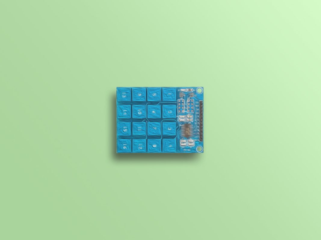
TTP229 Capacitive Touch Keypad Features
Keypads are one of the most popular components that are widely used in electronics. Everybody can communicate with different systems by switches. Normally, every key occupies one digital pin of the microcontroller. But by using a 4×4 keypad you can reduce the occupied pins. With this module, you can use all 16 switches by occupying only 2 pins of the microcontroller.
This 16 key capacitive touch keypad is based on the TTP229 IC. Output pins 1 to 8 are for direct switching on and off keys 1 to 8. There are also 2 serial pins to use the 16-key mode.
How it works
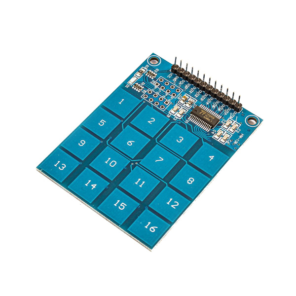
The 4×4 Keypad features a total of 16 buttons in a matrix form. This module can be adjusted in different modes. The most important ones are as follows:
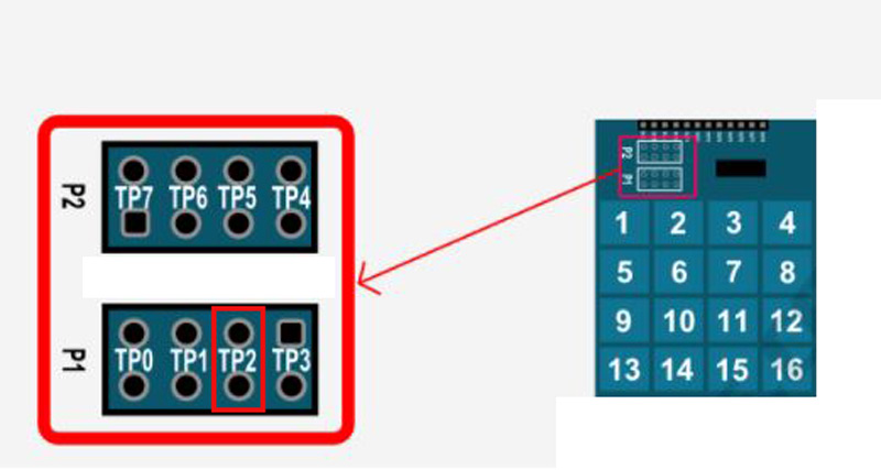
- Two TP2 pins are open-circuit: In this mode, only 8 output pins are active to use 8 touch keys. By touching each key, its relevant pin becomes HIGH and by releasing it, it becomes LOW again.
- Two TP2 pins are short-circuit: in this mode, 2 serial pins are active to use all 16 touch keys. You can only touch one key at a time.
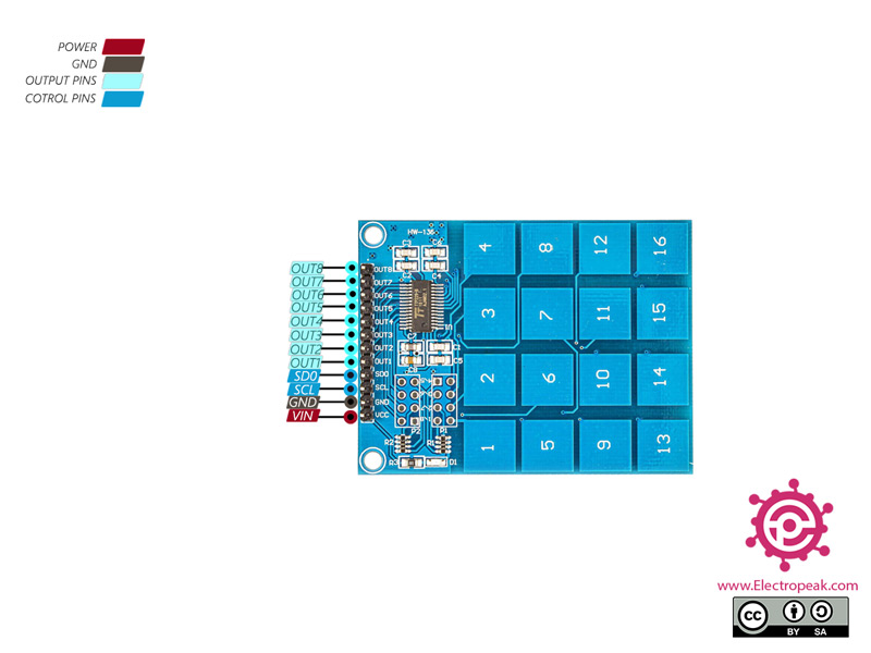
TTP229 Capacitive Touch Keypad Pinout
This module has 12 pins:
- VCC: Module power supply – 2.4-5.5V
- GND: Ground
- SCL: Input pin for Serial Clock
- SD0: Output pin for Serial Clock
- Out1: Digital Output pin 1
- Out2: Digital Output pin 2
- Out3: Digital Output pin 3
- Out4: Digital Output pin 4
- Out5: Digital Output pin 5
- Out6: Digital Output pin 6
- Out7: Digital Output pin 7
- Out8: Digital Output pin 8
You can see the pinout of this module here.
Required Materials
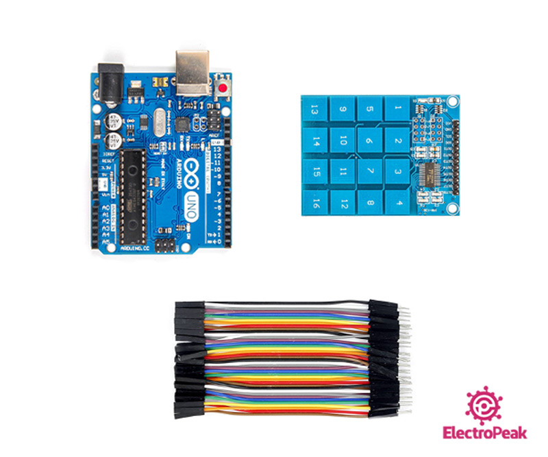
Hardware Components
Software Apps
Interfacing 4x4 TTP229 Capacitive Touch Keypad with Arduino
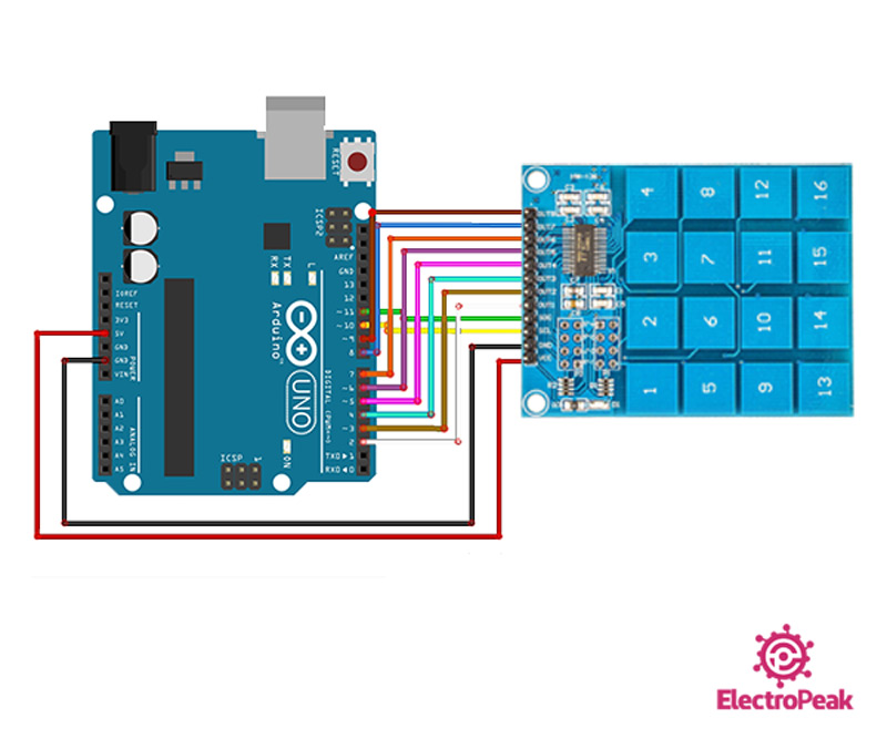
Step 1: Circuit
The following circuit shows how you should connect Arduino to TTP229 module. Connect wires accordingly.
Step 2: Code for 8 Key Mode
Upload the following code to Arduino. Note that for this mode, two TP2 pins must be open-circuit.
   /*
  XD-62B-TTP229-4x4-Keypad-8
  made on 11 Nov 2020
  by Amir Mohammad Shojaee @ Electropeak
  Home
*/

void setup(){
  for(int x=2;x<10;x++)
  pinMode(x,INPUT);
  Serial.begin(9600);
}

void loop(){
  for(int y=2;y<10;y++){
    if (digitalRead(y)==HIGH)
    Serial.println(y-1);
  }
}
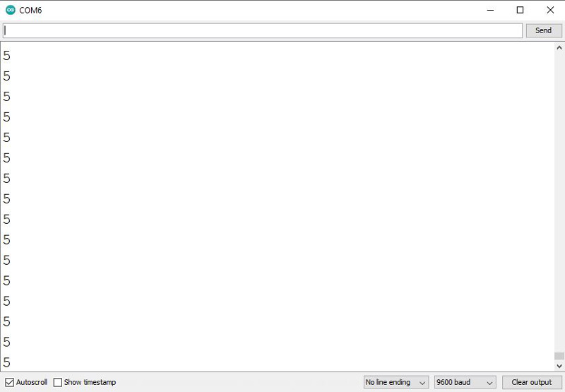
In this code, we have connected 8 Arduino pins (2 to 9) to the 8 buttons of the module, and by touching each key, its number will appear in the Serial Monitor.
The output is as follows. As you can see, key number 5 has been touched.
Step 3: Code for 16 Key Mode
Upload the following code to Arduino. Note that for this mode, two TP2 pins must be short-circuit.
    /*
  XD-62B-TTP229-4x4-Keypad-16
  modified on 11 Nov 2020
  by Amir Mohammad Shojaee @ Electropeak
  Home

  based on forum.hobbycomponents.com examples
*/

/* Define the digital pins used for the clock and data */
#define SCL_PIN 10
#define SDO_PIN 11

/* Used to store the key state */
byte Key;

void setup()
{
  /* Initialise the serial interface */
  Serial.begin(9600);
  /* Configure the clock and data pins */
  pinMode(SCL_PIN, OUTPUT);
  pinMode(SDO_PIN, INPUT);
}

/* Main program */
void loop()
{
  /* Read the current state of the keypad */
  Key = Read_Keypad();

  /* If a key has been pressed output it to the serial port */
  if (Key)
    Serial.println(Key);

  /* Wait a little before reading again
     so not to flood the serial port*/
  delay(100);
}


/* Read the state of the keypad */
byte Read_Keypad(void)
{
  byte Count;
  byte Key_State = 0;

  /* Pulse the clock pin 16 times (one for each key of the keypad)
     and read the state of the data pin on each pulse */
  for(Count = 1; Count <= 16; Count++)
  {
    digitalWrite(SCL_PIN, LOW);

    /* If the data pin is low (active low mode) then store the
       current key number */
    if (!digitalRead(SDO_PIN))
      Key_State = Count;

    digitalWrite(SCL_PIN, HIGH);
  }

  return Key_State;
}
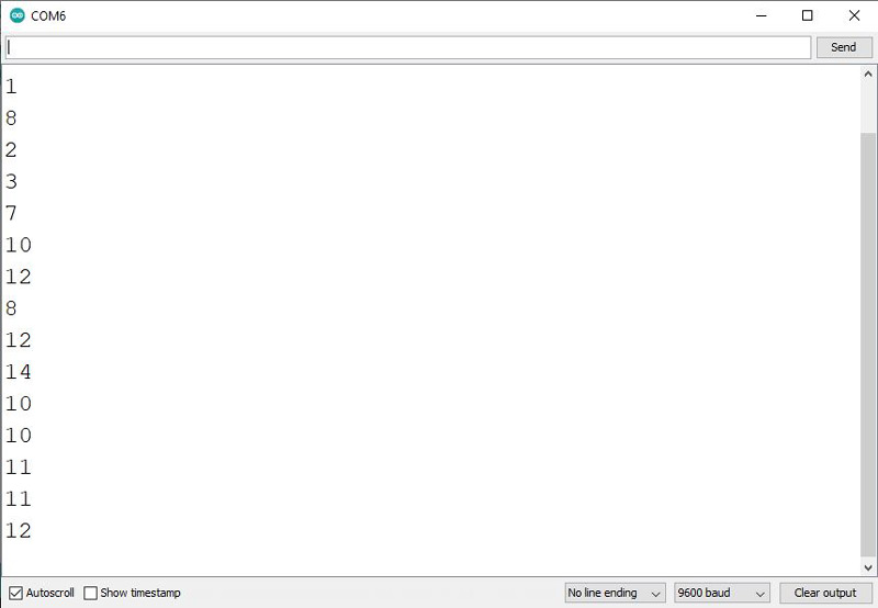
In this code, we receive data and send clock through two digital pins, one as input and the other as output. Finally, by touching each key, its relevant number will appear in the Serial Monitor.
The output is as follows. As you can see, different keys are accidentally touched.

Comments (4)
Ηi. My name is Jim and i am from Greece. Congratulations. I am a beginner to Arduino Mega and projects and I want to ask you something. I bought the Capacitive Touch Disk Pad (RobotDyn) with 16keys – I2C Capacitive Touch TTP229 Module. How can I use it so by touching each key, the relevant number appear in the Serial Monitor. I try the step 3 with MEGA 2560 (SCL 21 and SDA 20 pin) it loads the code, i press the number but nothing happens. (Sorry if there are any errors I use google translate)
Hi.
The touchpad you’ve bought is not similar to the one used in this project. So the code here will not help you with your module. Check the following link and see if that can be of any good. “https://github.com/TinkerYpsi/TT_TouchKeypadTTP229”
I had to modify the code to get it to work properly for I2C – The “for” loop shoudl start with 0 to get correct key number and I added a procedure that ensures only one number is returned when key is pressed.
Also my jumpers were numbered differently – you have to jump the third pair on bottom set as shown in the figure above, but mine are labeled P1-3 (or just 3)
/*
XD-62B-TTP229-4×4-Keypad-16
modified on 11 Nov 2020
by Amir Mohammad Shojaee @ Electropeak
https://electropeak.com/learn/
based on forum.hobbycomponents.com examples
*/
/* Define the digital pins used for the clock and data */
#define SCL_PIN 7
#define SDO_PIN 8
#define GND_KEY 6
#define VIN_KEY 5
/* Used to store the key state */
byte Key;
byte OldKey;
void setup()
{
/* Initialise the serial interface */
Serial.begin(9600);
/* Configure the clock and data pins */
pinMode(GND_KEY, OUTPUT); //energizing capacitive keypad
pinMode(VIN_KEY, OUTPUT);
digitalWrite(GND_KEY, LOW);
digitalWrite(VIN_KEY, HIGH);
pinMode(SCL_PIN, OUTPUT);
pinMode(SDO_PIN, INPUT);
OldKey = 0;
}
/* Main program */
void loop()
{
/* Read the current state of the keypad */
Key = Pressed_Key();
/* If a key has been pressed output it to the serial port */
if (Key)
Serial.println(Key);
}
/* Read the state of the keypad */
byte Read_Keypad(void)
{
byte Count;
byte Key_State = 0;
/* Pulse the clock pin 16 times (one for each key of the keypad)
and read the state of the data pin on each pulse */
for(Count = 0; Count <= 16; Count++)
{
digitalWrite(SCL_PIN, LOW);
/* If the data pin is low (active low mode) then store the
current key number */
if (!digitalRead(SDO_PIN))
Key_State = Count;
digitalWrite(SCL_PIN, HIGH);
}
return Key_State;
}
/* returns new key pressed or 0 if nothign is pressed or key is held down*/
byte Pressed_Key()
{
byte Key_press;
Key_press = Read_Keypad();
if (Key_press == OldKey) Key_press = 0;
else if (Key_press != 0) OldKey=Key_press;
else OldKey = 0;
delay(20);
return Key_press;
}
Thanks for sharing your experience!