
Overview
What You Will Learn
- How to use the ESP8266 module.
- How to control objects with this module using a WIFI connection.
What is the ESP8266 Module?
ESP8266 is one of the most practical modules for wireless connection (WIFI). These modules can be used in both server and client operating modes.
You can use this module easily using AT Command.
Here are some of its most important commands:
| Command | Response | Description |
|---|---|---|
| AT | OK | Test |
| AT+RST | OK | Reset module |
| AT+GMR | OK | View version info |
| AT+CIOBAUD = 9600 | OK | Change baud rate to 9600 |
| AT+CWMODE | +CWMODE:( value scope of ) OK | WIFI mode |
| AT+CWSAP? | +CWSAP:,,, | Configuration of softAP mode |
| AT+CWSAP=,,, | +CWSAP:,,, | Set configuration of softAP mode |
| AT+CIPMUX | OK or ERROR | The configuration of the softAP mode |
| AT+CIPSERVER | OK | Configure as server |
You can check the modules datasheet for more AT Commands.
Use the code below to test AT Commands and change the modules setups (such as changing the SSID name, changing the password, and changing the baud rate).
#include <SoftwareSerial.h>
SoftwareSerial mySerial(2, 3);  //RX,TX

//  Arduino pin 2 (RX) to ESP8266 TX
//  Arduino pin 3 to voltage divider then to ESP8266 RX
//  Connect GND from the Arduiono to GND on the ESP8266
//  Pull ESP8266 CH_PD HIGH

void setup()
{
    Serial.begin(9600);     // communication with the host computer
    // Start the software serial for communication with the ESP8266
    mySerial.begin(9600);

    Serial.println("");
    Serial.println("Remember to to set Both NL & CR in the serial monitor.");
    Serial.println("Ready");
    Serial.println("");
}

void loop()
{
    // listen for communication from the ESP8266 and then write it to the serial monitor
    if ( mySerial.available() )   {  Serial.write( mySerial.read() );  }
    // listen for user input and send it to the ESP8266
    if ( Serial.available() )       {  mySerial.write( Serial.read() );  }
}Project 1: Controlling a LED over Network Using ESP8266 Module
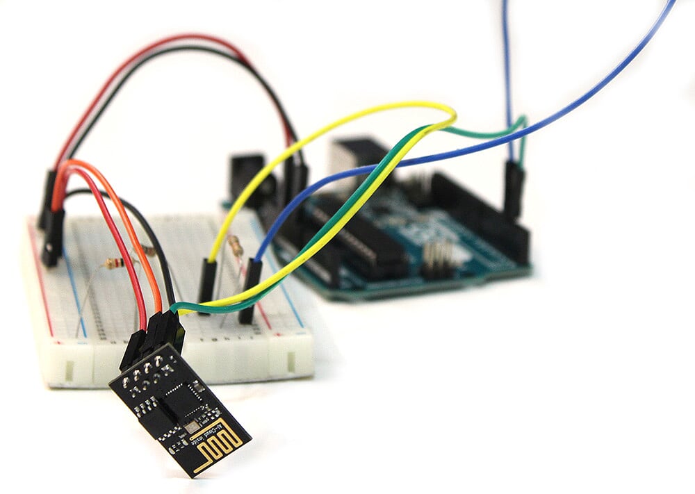
Circuit

Code
Note
#include <SoftwareSerial.h>
SoftwareSerial esp8266(2, 3);
It is simpler to use software serial to connect the module.
#define led_pin 13Determining pin 13 as the connected pin to LCD
String esp8266Serial(String command, const int timeout)
{
  String response = ""; // a String to hold incoming data
  esp8266.print(command);
  long int time = millis();
  while ( (time + timeout) > millis())
  {
    while (esp8266.available())
    {
      char c = esp8266.read(); // Read the answer of ESP8266 character by character
      response += c;
    }
  }
    Serial.print(response);

  return response;
}
Defining a function called esp8266serial with two inputs.
Command: a string of AT Commands
Timeout: the time after sending AT Command that the code execution stops and waits for the response from the ESP8266.
The output of this function is the received response from the ESP8266.
Note: millis() command gives you the elapsed time code execution. For more information check this link
void setup()
{
  pinMode(led_pin, OUTPUT);
  digitalWrite(led_pin, LOW);
  Serial.begin(9600);
  esp8266.begin(9600); //Baud rate for communicating with ESP8266. Your's might be different.
  esp8266Serial("AT+CWMODE=3\r\n", 1000);
  esp8266Serial("AT+CIPMUX=1\r\n", 1000);
  esp8266Serial("AT+CIPSERVER=1,8888\r\n", 1000);
}
In the setup part, first, define the pin which is connected to LED as output and set it LOW.
Set the hardware serial baud rate at 9600.
Then place the module in server mode with the next three commands.
void loop()
{
  if (esp8266.available())
  {
    if (esp8266.find("+IPD,"))
    {
      String msg;
      msg = esp8266.readStringUntil('.');
      String command1 = msg.substring(0, 3);
      String command2 = msg.substring(4);

      if (command2 == "ON")
      {
        Serial.println("LED Turn ON");
        digitalWrite(led_pin, HIGH);
      }
      else if (command2 == "LED Turn OFF")
      {
        Serial.println("OFF");
        digitalWrite(led_pin, LOW);
      }
    }
  }
} Project2: Controlling a LED by Connecting to WIFI & a HTTP Page
Warning
Circuit
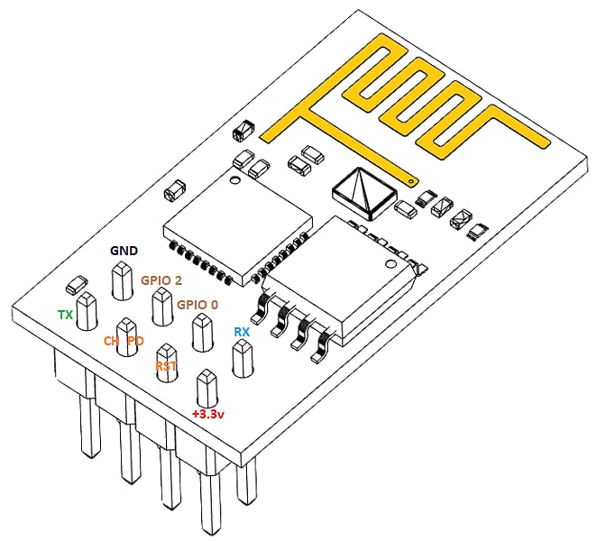
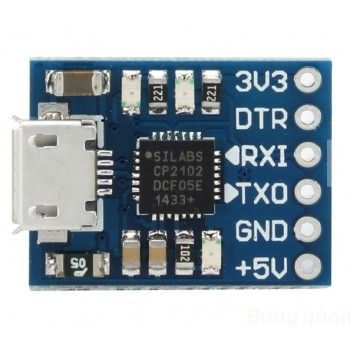
| SERIAL TO USB CONVERTER | ESP8266 |
|---|---|
| 3.3v | 3.3V |
| GND | GND |
| RX | TX |
| TX | RX |
| 3.3v | CH_PD |
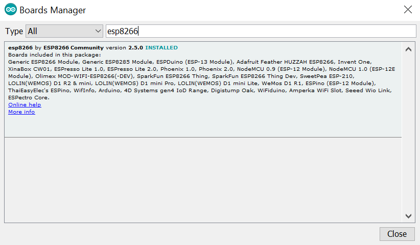
Installing the ESP8266 Library and Boards
Follow these steps:
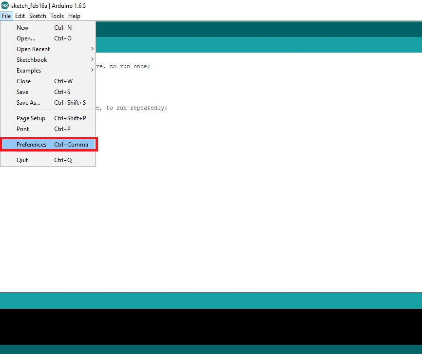
Step 1– Go to file>preferences
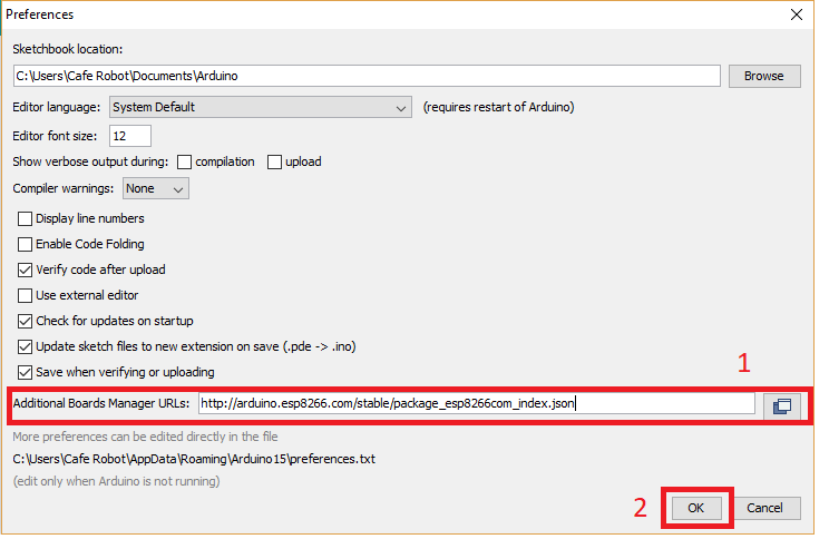
Step 2: Enter the following address in Additional Board Manager URLs
http://arduino.esp8266.com/stable/package_esp8266com_index.json
Code
#include <ESP8266WiFi.h>
#include <WiFiClient.h>
#include <ESP8266WebServer.h>
/* Set these to your desired credentials. */
const char *ssid = "*****"; //Enter your WIFI ssid
const char *password = "*****"; //Enter your WIFI password
ESP8266WebServer server(80);
void handleRoot() {
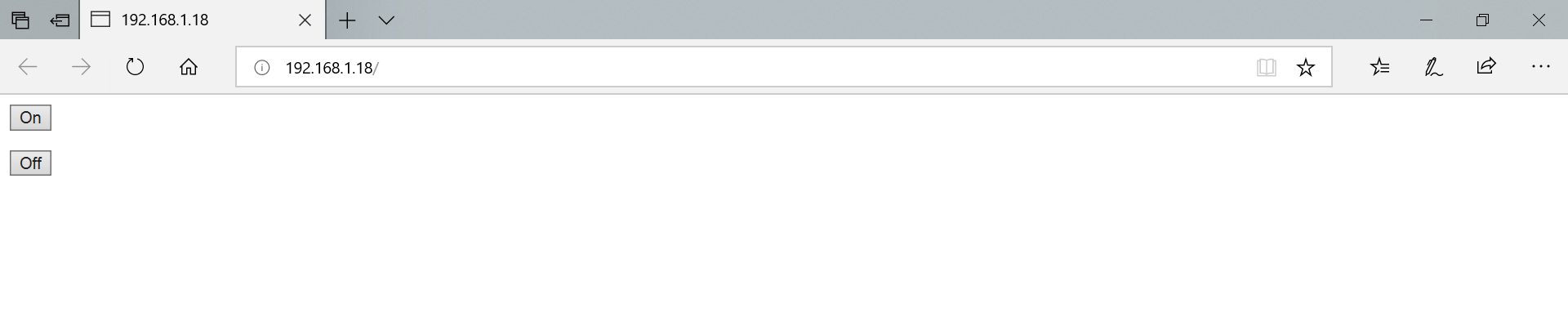
server.send(200, "text/html", "<form action=\"/LED_BUILTIN_on\" method=\"get\" id=\"form1\"></form><button type=\"submit\" form=\"form1\" value=\"On\">On</button><form action=\"/LED_BUILTIN_off\" method=\"get\" id=\"form2\"></form><button type=\"submit\" form=\"form2\" value=\"Off\">Off</button>");
}
void handleSave() {
if (server.arg("pass") != "") {
Serial.println(server.arg("pass"));
}
}
void setup() {
pinMode(LED_BUILTIN, OUTPUT);
delay(3000);
Serial.begin(115200);
Serial.println();
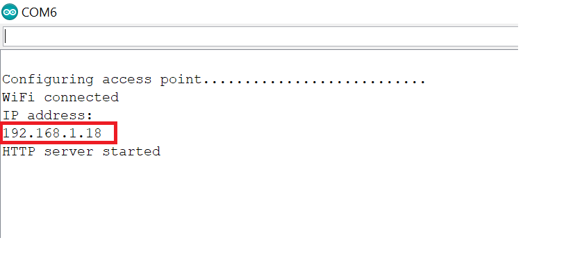
Serial.print("Configuring access point...");
WiFi.begin(ssid, password);
while (WiFi.status() != WL_CONNECTED) {
delay(500);
Serial.print(".");
}
Serial.println("");
Serial.println("WiFi connected");
Serial.println("IP address: ");
Serial.println(WiFi.localIP());
server.on ( "/", handleRoot );
server.on ("/save", handleSave);
server.begin();
Serial.println ( "HTTP server started" );
server.on("/LED_BUILTIN_on", []() {
digitalWrite(LED_BUILTIN, 1);
Serial.println("on");
handleRoot();
});
server.on("/LED_BUILTIN_off", []() {
digitalWrite(LED_BUILTIN, 0);
Serial.println("off");
handleRoot();
});
}
void loop() {
server.handleClient();
}You should upload the code on the module after defining your WIFI SSID and PASSword.
Follow these steps to upload the code and execute it:
- Connect the module to the converter and then connect the converter to the computer
- Connect the GPIO0 pin of the module to ground. Then connect the RESET pin to ground for a moment. Then return both pins to their initial state. (you can also leave them without connecting.)
- Choose Generic ESP8266 Module in Arduino software for your board model. (make sure that upload speed is on 115200)

4. Choose the port and click upload to upload the code on the module.
5. Open serial monitor after uploading is done, and wait for the IP address of your HTTP page to be shown.
6. Enter IP in your browser to see the following page:
Buy an ESP8266 Wifi Module
What’s Next?
- Try to control two relays with your phone using WIFI connection.
- Try to control a robot with your phone using WIFI connection

Comments (2)
You guys are the BEST!!! Thank-you for all your hard work. I will be pouring over your projects which are helping me learn so much about these products.
Thank you for your kind words. You’re most welcome!