
Product added to cart

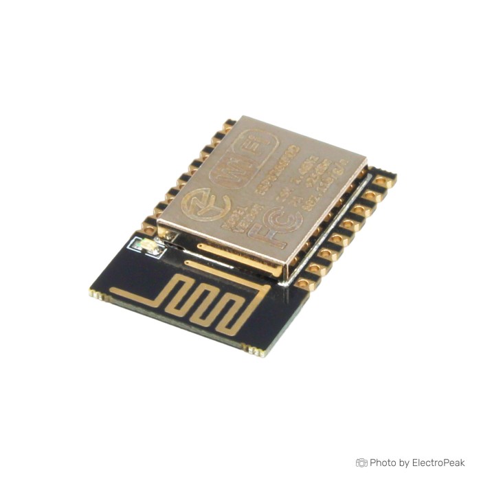
ESP-12E ESP8266 Wi-Fi Module
$1.2600
In stock
SKU
COM-03-019
Volume discounts:
- +50 4 % $1.2100
- +100 6 % $1.1900
- +300 8 % $1.1600
- +500 10 % $1.1400
- +1000 12 % $1.1100
Product Variations:
-
 ESP-12F ESP8266 Wi-Fi Module
COM-03-023 - Ai Thinker ESP-12F ESP8266 WiFi Module
COM-03-063 - ESP-12E ESP8266 Wi-Fi Module
COM-03-019 - ESP-07 ESP8266 Wi-Fi Module - IPX Antenna
COM-03-053 - ESP-12N ESP8266 Wi-Fi Development Board
COM-03-038 - Ai Thinker ESP-12S ESP8266 WiFi Module
COM-03-061 - ESP-07S ESP8266 Wi-Fi Module
COM-03-054 - ESP-12S ESP8266 Wi-Fi Module
COM-03-046


Add an Accessory:
- ESP-01/ESP12/ESP32 Universal Downloader Burning Fixture Test Board Programmer$4.9500
- NodeMCU LUA ESP8266 12E/12F Wi-Fi Development Board$1.9500


View more


Ships in 2-3 business days, then:
Free delivery in 12-15 days by Tracked Economic Shipping on orders over $100.
Free delivery in 7-10 days by Express Shipping on orders over $300.
More shipping info

Shop with confidence Learn More
 Ai-Thinker ESP-01 ESP8266 WiFi Module - PCB Antenna Previous
ESP-12E ESP8266 Wi-Fi Module Review
The ESP-12E ESP8266 Wi-Fi Module is a compact 24x16 mm wireless transceiver for embedded IoT projects. It combines an onboard 32-bit microcontroller, 4 MB flash memory, and 11 GPIO pins with integrated 2.4 GHz networking. It supports custom firmware development in the Arduino IDE as well as serial modem workflows using AT commands.
This is a bare surface-mount module with castellated edge pads, not a plug-and-play USB development board. Integration requires an external regulated 3.3 V power source, appropriate boot-pin pull resistors, and an external serial interface for flashing firmware. It suits engineers and makers building custom PCBs or space-constrained hardware where a small footprint and low hardware overhead matter. It is not the easiest choice for beginners who need integrated USB programming, onboard power regulation, or breadboard-friendly pin spacing without adapters.
Production batches of bare ESP-12E modules can vary between suppliers, and this specific version is supplied without specified branding or factory certification markings. If your application specifically requires an Ai-Thinker-branded ESP-12E option, that version is listed separately. For other form factors, pin counts, or assembled breakout boards, browse our wider selection of ESP8266 modules and development boards.
Specifications of ESP-12E ESP8266 Wi-Fi Module
- Processor: Tensilica L106 32-bit
- Processor speed: 80 to 160 MHz
- Flash memory: 4 MB
- RAM: 50 KB
- Wi-Fi interface: IEEE 802.11 b/g/n
- Operating voltage: 3.0 to 3.6 V
- Supported protocols: TCP/IP
- Supported protocols: UDP
- Supported protocols: HTTP
- Supported protocols: MQTT
- GPIO pins: 11
- Dimensions: 24x16 mm
- I2S port: Yes
- Serial communication: UART
- Serial communication: SPI
- Serial communication: I2C
- Programming methods: Arduino IDE
- Programming methods: AT commands
ESP-12E GPIO, power and programming specifications
The ESP-12E is built around the Tensilica L106 32-bit RISC processor. Although the specification lists an operating range of 80 to 160 MHz, 80 MHz is the standard operating baseline. Switching the core clock to 160 MHz in software increases compute throughput for tasks such as crypto or local web serving, but also increases power draw and thermal output.
Storage consists of 4 MB of external SPI flash memory, providing space for embedded user code, Over-the-Air (OTA) firmware updates, and lightweight SPIFFS or LittleFS filesystems. Internal memory is listed at 50 KB of usable RAM, handling typical network buffers, TCP stack overhead, and sensor routines. Built-in network support covers IEEE 802.11 b/g/n networks and core IoT networking protocols including TCP/IP, UDP, HTTP, and MQTT.
The module exposes 11 usable GPIO pins, so careful pin budgeting is required. Certain pins serve dual purposes during system boot and cannot be connected arbitrarily to external hardware without disrupting startup states. Peripheral support covers standard embedded buses:
- UART: Primary hardware serial interface for firmware flashing, debug logging, and AT-command communication.
- SPI: Hardware SPI bus for high-speed peripherals such as displays, flash memory, or external sensors.
- I2C: Supported through software bit-banging across assignable GPIO pins.
- I2S: Audio interface multiplexed across existing GPIO pins rather than routed to dedicated edge pins.
For custom firmware, programming through the Arduino IDE requires installing the ESP8266 board core and selecting a generic ESP8266 module profile. Using the module as a Wi-Fi modem with AT commands requires dedicated AT firmware to be flashed to the module. For safe pin assignments around startup strapping pins, consult the ESP8266 GPIO pinout reference. When prototyping on standard 2.54 mm pitch sockets, an ESP-12 breakout adapter board brings the 2.0 mm castellated pads out to standard headers.
ESP-12E ESP8266 compatibility and 3.3V requirements
The ESP-12E operates strictly within a 3.0 to 3.6 V supply range. The entire chip architecture, including all digital I/O lines, uses 3.3 V logic. Applying 5 V directly to the power rail or any GPIO pin will permanently damage the silicon. Systems that interface with 5 V microcontrollers or digital sensors require inline bidirectional logic level shifters.
Wi-Fi transmission generates sharp current spikes exceeding 170 to 250 mA. If the 3.3 V power rail sags during these RF bursts, the processor will brown out and reset spontaneously. Weak onboard regulators on standard USB-to-serial bridges are a frequent source of instability. A dedicated supply, such as a regulated 3.3 V breadboard power module with decoupling capacitors placed near the VCC and GND pins, keeps the supply rail clean.
Because the ESP-12E is a bare module, its boot mode is governed entirely by the state of specific strapping pins when reset is released. For a normal flash boot, use the following hardware configuration:
- CH_PD (EN): Pulled high to 3.3 V to enable the chip.
- GPIO15: Pulled low to GND via a resistor.
- GPIO0: Pulled high to 3.3 V during normal startup; pulled low to GND during reset to enter UART programming mode.
- GPIO2: Pulled high to 3.3 V during reset.
- RST: Pulled high to 3.3 V for normal running; pulled low to trigger a hardware reset.
The single integrated analog input (TOUT/ADC0) has an internal input range of 0 to 1.0 V. Connecting raw 3.3 V or 5 V analog signals will saturate or burn out the ADC. An external voltage-divider resistor network is required to scale signals down to the 1.0 V threshold.
The onboard PCB trace antenna works well in free air or plastic enclosures. For designs mounted inside a metal cabinet, an ESP8266 module with an IPX external-antenna socket allows external antenna routing. If your application outgrows the ESP8266 architecture and requires built-in USB, more processing power, and Bluetooth connectivity, consider an ESP32 Wi-Fi and Bluetooth development-board approach.
ESP-12E ESP8266 limitations and common mistakes
Working with bare ESP8266 modules involves hardware constraints that must be addressed during system design:
- Strict 3.3 V logic: The chip is not 5 V tolerant. Direct exposure to 5 V logic rails from legacy boards will destroy the I/O pads.
- Boot-pin strapping: GPIO0, GPIO2, and GPIO15 dictate the boot sequence. Peripherals that pull these pins high or low during power-on will prevent normal boot or trigger unintended flashing states. Review the ESP8266 GPIO pinout reference before routing traces.
- Single 0–1 V ADC channel: The analog converter cannot read standard 3.3 V sensors directly and provides only one input channel.
- Software I2C: The ESP8266 lacks a dedicated hardware I2C controller and handles communication through software bit-banging instead.
- Flash write modes: While most tools handle SPI communication smoothly, some module batches fail during flashing when configured for QIO mode; switching the programmer settings to DIO mode often resolves upload errors.
- Deep-sleep power draw: Achieving bare-chip microamp sleep currents requires careful board design. External pull-ups, floating input pins, and leakage through peripheral circuits will significantly increase total sleep current.
- No native USB interface: Flashing and serial debugging require an external USB-to-TTL adapter.
- Firmware state at delivery: Modules do not necessarily arrive pre-programmed with functional AT firmware; do not assume AT commands will respond without flashing them first.
For applications that only need basic Wi-Fi serial passthrough and minimal external wiring, a smaller basic ESP8266 Wi-Fi module with limited GPIO offers a simpler layout with fewer broken-out pins to manage.
ESP-12E Wi-Fi module projects and embedded uses
The ESP-12E fits projects where physical space is limited and an integrated microcontroller eliminates the need for a secondary host board. Common ESP8266-platform implementations include:
- Wireless Telemetry and Environmental Nodes: Reading temperature, humidity, or barometric pressure sensors over I2C and publishing metrics through MQTT or HTTP endpoints.
- Smart Home Actuators: Controlling solid-state or mechanical relays, smart sockets, and LED lighting strings through local web interfaces or home automation hubs.
- Miniature Status Displays: Driving low-power I2C OLED screens to show network clocks, weather forecasts, or server uptime synchronized through NTP.
- Serial-to-Wi-Fi Bridges: Flashing standard AT or custom bridge firmware to provide wireless network access to an otherwise disconnected microcontroller.
Its compact 24x16 mm form factor suits direct surface mounting on custom production PCBs. On the bench, pairing the module with an ESP-12 breakout adapter board lets you evaluate peripherals on a solderless breadboard before committing to a final PCB layout. If you are configuring the software environment for the first time, follow our ESP8266 Arduino IDE setup guide for board manager instructions.
ESP-12E programming setup and required accessories
Programming and testing an ESP-12E bare module on the workbench requires external supporting hardware. A complete setup includes power regulation, a serial bridge, and prototype wiring accessories.
Required
- Stable 3.3 V Power Supply: Wi-Fi RF peaks require dedicated current handling. A regulated 3.3 V breadboard power supply provides a clean rail isolated from weak USB conversion ports.
- 3.3 V USB-to-TTL Adapter: Necessary for uploading code over UART. Use a 3.3 V USB-to-TTL programmer based on the CH340G, or a CP2102 USB-to-UART programmer. Ensure the logic selector switch is set strictly to 3.3 V.
- Boot Configuration Resistors: Pull-up resistors (10 kΩ) for CH_PD, RST, and GPIO2, alongside pull-down resistors for GPIO15 and a momentary switch to pull GPIO0 low during flashing.
Recommended
- Adapter Breakout Board: The castellated pads use a 2.0 mm pitch that does not fit standard 2.54 mm breadboards. An ESP-12 breakout adapter board solders directly to the module and exposes standard breadboard pins.
- Prototyping Workspace: A standard solderless breadboard for module prototyping holds the breakout and wiring securely.
- Interconnects: A set of jumper wires for UART and boot wiring simplifies temporary connections between the programmer, breakout board, and power module.
- Decoupling Capacitors: A 10 µF electrolytic paired with a 100 nF ceramic capacitor placed directly across the module's VCC and GND pins suppresses transient voltage dips.
- Logic Level Shifters: Required whenever interfacing the ESP-12E with 5 V sensors or microcontrollers.
- Analog Scaling Network: A resistor-divider circuit is necessary if your analog inputs exceed the 0 to 1.0 V limit.
Quick Start Verification Procedure
- Solder the ESP-12E to a breakout board and seat it in your breadboard.
- Connect regulated 3.3 V to VCC and common GND. Tie CH_PD, RST, and GPIO2 to 3.3 V through 10 kΩ resistors. Tie GPIO15 to GND through a 10 kΩ resistor.
- Connect your 3.3 V serial adapter: Module TX to programmer RX, and Module RX to programmer TX. Ensure programmer GND connects to the common power ground.
- Pull GPIO0 to GND, then momentarily pull RST to GND to boot into UART download mode.
- Open the Arduino IDE, ensure the ESP8266 board package is installed, select "Generic ESP8266 Module", and upload a basic Wi-Fi network scanner sketch.
- Disconnect GPIO0 from GND, toggle RST low and high again to trigger a normal boot, and verify serial console output at the configured baud rate.
For detailed toolchain installation and driver troubleshooting, refer to our complete ESP8266 Arduino IDE setup guide.
ESP-12E ESP8266 Wi-Fi Module FAQ
Is the ESP-12E ESP8266 Wi-Fi Module 5V tolerant?
No. The module is not 5 V tolerant. It requires an operating voltage between 3.0 and 3.6 V, and its GPIO pins are designed strictly for 3.3 V logic levels. Connecting 5 V directly to the power pins or digital I/O lines will permanently damage the chip. Use level shifting when interfacing with 5 V circuits.
How many GPIO pins can I use on the ESP-12E?
The module lists 11 usable GPIO pins. Practical pin allocation must account for boot strapping constraints. GPIO0, GPIO2, and GPIO15 dictate startup modes when the chip resets, so external hardware must not force them into invalid states during boot. Consult the ESP8266 GPIO pinout reference to plan safe assignments.
Can I power the ESP-12E directly from USB 5V?
No, you cannot power it directly from a 5 V USB line. Place a low-dropout 3.3 V regulator capable of handling transmit spikes between the USB 5 V rail and the module's VCC pin. Insufficient regulator capacity leads to spontaneous resets during Wi-Fi transmission.
Why will an ESP-12E not boot or enter programming mode?
Incorrect boot-pin states or power rail noise are the primary causes. For normal booting, GPIO15 must be pulled low, while GPIO0, GPIO2, and CH_PD must be pulled high. To enter UART flashing mode, GPIO0 must be tied low while the reset pin is toggled. If these pins float, or the 3.3 V supply sags under load, the processor will fail to initialize.
What analog voltage can the ESP-12E ADC read?
The internal ADC pin reads a maximum range of 0 to 1.0 V. If your analog sensor outputs a 0 to 3.3 V or 0 to 5 V signal, implement an external resistive voltage divider to scale the signal below 1.0 V before routing it to the TOUT pin.
Do I need a USB-to-TTL adapter to program the ESP-12E?
Yes. An external adapter is required because the bare module contains no onboard USB bridge. Use a 3.3 V serial tool such as the CP2102 USB-to-UART programmer to connect the module's TX and RX pins with your computer.
Does the ESP-12E support Arduino IDE and AT commands?
Yes, both workflows are supported. Writing custom code through the Arduino IDE requires adding the ESP8266 board core through the Boards Manager. Using AT commands requires flashing standard AT firmware first, as bare modules are not guaranteed to have AT firmware pre-installed.
When should I choose an ESP-07 or ESP32 board instead?
Choose the ESP8266 module with an IPX external-antenna socket if your project is housed in a shielded enclosure that requires an external antenna. If you need a fully integrated prototyping platform with onboard USB, Bluetooth connectivity, and higher GPIO density, choose an ESP32 board with onboard USB programming.
ESP-12E ESP8266 buying checklist
Before purchasing the ESP-12E, confirm that your project requirements match its bare-module architecture:
- Ideal for: Compact custom PCB designs, space-constrained smart home devices, MQTT sensor nodes, and developers comfortable with external 3.3 V power regulation and UART boot-pin wiring.
- Consider with preparation: Arduino IDE users willing to assemble breadboard adapters, 3.3 V regulators, and USB-to-serial programmers before writing code.
- Avoid if: You need plug-and-play USB connectivity, native 5 V logic tolerance, multiple analog inputs, Bluetooth, or an external antenna jack.
Use this pre-purchase verification list to confirm you have the required supporting parts:
- [ ] The design operates on 2.4 GHz Wi-Fi and does not require Bluetooth.
- [ ] You have a regulated 3.0 to 3.6 V power source capable of handling 250 mA peaks.
- [ ] All interconnected digital logic lines operate at 3.3 V or use level shifters.
- [ ] The project fits within the 11 GPIO allocation without conflicting with boot strapping pins.
- [ ] Any analog input voltages are scaled down to the 0–1.0 V limit.
- [ ] You have a 3.3 V USB-to-TTL serial converter for programming.
- [ ] Pull-up and pull-down resistors are on hand for the boot and reset circuits.
- [ ] An onboard PCB trace antenna provides adequate range for your installation.
If your manufacturing requirements demand a specific branded source, review the Ai-Thinker-branded ESP-12E option. For broader hardware needs, including Bluetooth or high I/O counts, evaluate the ESP32 Wi-Fi and Bluetooth development-board approach, or compare other module formats across our full range of ESP8266 modules and development boards.
| MCU/SoC | ESP8266 |
|---|---|
| Product Family | ESP8266 |
| Architecture | Tensilica L106 32-bit |
| CPU Cores | 1 |
| Clock Speed (MHz) | 80 to 160 MHz |
| Flash | 4 MB |
| SRAM | 50 KB |
| GPIO Pins | 11 |
| SPI interface Pins | 1 |
| I2C interface Pins | 1 |
| UART interface Pins | 1 |
| USB Ports | No |
| CAN Bus Support | No |
| Ethernet Support | No |
| ADC Channels | 1 |
| DAC Channels | No |
| Operating Voltage (V) | 3.0 to 3.6 V |
| GPIO Voltage (V) | 3.3V |
| Wireless | Wi-Fi |
| Form Factor | 24x16 mm |
| IDE Support | Arduino IDE, AT commands |
| Input Voltage (V) | 3.0 to 3.6 V |
| Antenna Type | Internal Antenna |
| Bluetooth Ver. | No |
Write Your Own Review

Please complete your information below to login.
Sign In
Create New Account