
Product added to cart

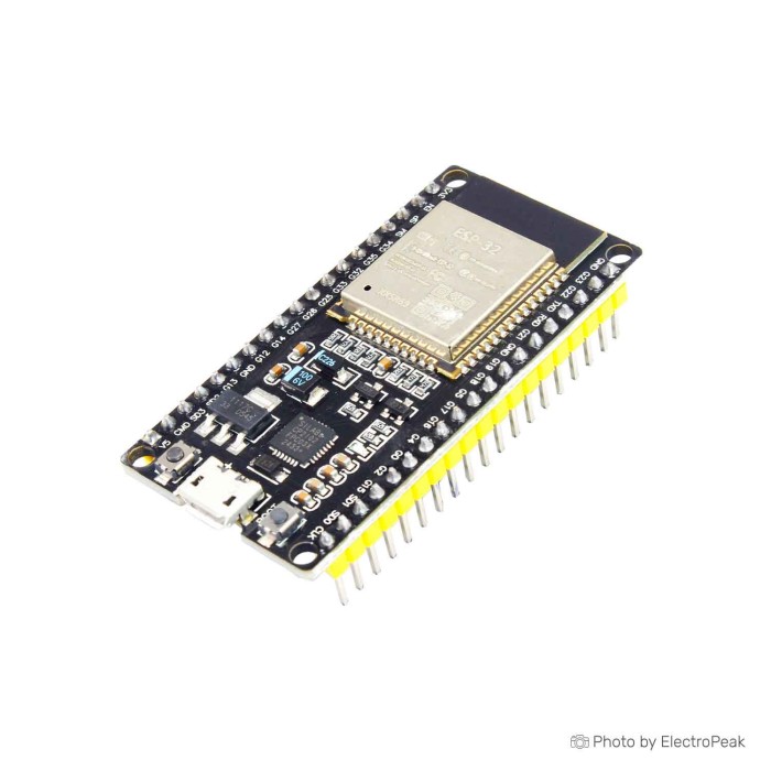
ESP-WROOM-32 ESP32 Development Board - CP2102 Driver
SAVE $1.3000
$5.9500 $7.2500
In stock
SKU
COM-03-037
Product Variations: View out of stock variants
-
 ESP-WROOM-32 ESP32 Development Board - CP2102 Driv
COM-03-037 - ESP32 WROOM-32U Development Board- CP2102 Driver
COM-03-079 - ESP32 WROOM-32D CP2102 WiFi Bluetooth Development
COM-03-048 - Esp32 Wroom 32D Coreboard Wifi BLE Development Boa
COM-03-081 - NodeMCU-32S ESP32-S Wi-Fi Bluetooth Development Bo
COM-03-039Out of stock


Add an Accessory:


Ships in 2-3 business days, then:
Free delivery in 12-15 days by Tracked Economic Shipping on orders over $100.
Free delivery in 7-10 days by Express Shipping on orders over $300.
More shipping info

Shop with confidence Learn More
 ESP32-WROVER-B ESP32 Wi-Fi Bluetooth Development Board Previous
ESP-WROOM-32 Board CP2102 Review
This ESP-WROOM-32 development board combines Espressif's dual-core microcontroller with onboard 2.4 GHz Wi-Fi, Bluetooth 4.2, multiple peripheral buses, and a Silicon Labs CP2102 USB-to-UART bridge. At US$6.75, with volume pricing available, it is an economical hardware target for connected prototyping in Arduino and ESP-IDF environments. It suits rapid software evaluation, sensor nodes, and network automation, delivering dual-core compute at a low entry price.
Before designing this board into a project enclosure or long-term assembly, note that its carrier-board layout is not fully standardized. Specific PCB dimensions, mounting hole locations, the precise USB connector type, the onboard regulator model, and the exact module revision are not published. It works well for breadboarding and functional software development, but it is not intended for production systems that require guaranteed bill-of-materials traceability or verified mechanical clearances.
Specifications of ESP-WROOM-32 ESP32 Development Board - CP2102 Driver
- Microcontroller: ESP32-D0WDQ6 (dual-core)
- CPU Frequency: Up to 240 MHz
- Flash Memory: 4 MB
- SRAM: 520 KB
- Wi-Fi: 802.11 b/g/n
- Bluetooth: Bluetooth 4.2 BR/EDR and BLE
- Digital I/O Pins: 38
- Analog Input Pins: 18
- Interfaces: UART, SPI, I2C, PWM, ADC, DAC interfaces
- USB-to-Serial Chip: CP2102
- Operating Voltage: 3.3V
- Dimensions: Varies based on board design
Several hardware details remain unconfirmed before physical delivery. The board does not state whether it arrives with a Micro-USB or alternate port, and a USB cable is not included in the package. If your board arrives with a Micro-USB port, a standard Micro-USB data cable for programming provides the data lines required for serial communication. For general board comparisons and pin layouts across similar platforms, browse ESP32 development boards or consult our ESP32 first setup and programming guide to verify initial workstation prerequisites.
ESP32 CP2102 Specifications Explained
Knowing how the core silicon features translate to embedded firmware helps prevent common memory bottlenecks and communication conflicts. The specifications below outline practical hardware capabilities and architectural limits during prototyping.
| Specification | Technical Value | Why It Matters in Practice |
|---|---|---|
| Microcontroller Core | ESP32-D0WDQ6 (Dual-core up to 240 MHz) | Allows running heavy networking tasks (Wi-Fi/BLE protocol stacks) on one core while dedicating the second core to real-time control, sensor reading, or UI tasks. The actual clock speed is configurable in firmware to balance processing speed against power consumption. |
| Flash Memory | 4 MB | Stores firmware, partition tables, and SPIFFS/LittleFS file assets. It easily supports basic OTA (over-the-air) update partitions, but projects utilizing full Bluetooth stacks alongside large web interfaces can push memory limits. |
| Internal SRAM | 520 KB | Provides system memory for execution and dynamic memory allocation. Total chip memory is divided between instruction/data RAM and reserved network stack buffers, leaving a smaller portion available for direct heap allocation. |
| Wi-Fi | 802.11 b/g/n (2.4 GHz) | Connects to standard local networks for MQTT, HTTP, and local web servers. It operates exclusively on 2.4 GHz bands and does not support 5 GHz network infrastructure. |
| Bluetooth | Bluetooth 4.2 BR/EDR and BLE | Supports both Classic Bluetooth (useful for SPP serial emulation) and Bluetooth Low Energy (BLE) for mobile communication and low-overhead sensor beacons. |
| Peripheral Interfaces | UART, SPI, I2C, PWM, ADC, DAC | The ESP32 features an internal GPIO multiplexing matrix, meaning peripheral signals can be reassigned to various physical pins in software rather than being hardwired to fixed traces. |
| USB-to-Serial Bridge | Silicon Labs CP2102 | Translates hardware UART signals to a virtual serial port on your development computer for flashing and serial monitoring. Requires standard CP210x VCP drivers if your operating system does not automatically detect the bridge. |
For projects processing large audio buffers, holding framebuffers for high-resolution graphics, or managing expanded SSL/TLS cryptographic memory, 4 MB of flash and internal SRAM may fall short. Move to an ESP32 board with more flash and PSRAM for 16 MB flash alongside 8 MB external pseudo-static RAM. For initial development environment configuration, follow our guide to install ESP32 support in Arduino IDE.
ESP32 CP2102 Pin, Power and Wi-Fi Limitations
Although the hardware specification lists 38 digital I/O pins and 18 analog channels, practical circuit design requires working around internal silicon constraints. Misunderstanding pin allocations or logic voltages can cause boot failures, faulty sensor readings, or permanent hardware damage.
Connecting signals requires careful attention to these pin categories:
- Flash-connected pins (GPIO6–GPIO11): These lines connect internally to the SPI flash integrated inside the ESP-WROOM module. Even if physically exposed on carrier headers, connecting external hardware to these pins disrupts memory bus communication and crashes the system.
- Input-only pins (GPIO34, GPIO35, GPIO36, GPIO39): These lines lack internal pull-up/pull-down resistors and cannot be configured as digital outputs. They function only as digital inputs or analog ADC lines.
- Boot-strapping pins (GPIO0, GPIO2, GPIO5, GPIO12, GPIO15): The chip checks the logic voltage on these pins during reset to determine boot modes (flashing vs. normal execution) and internal regulator voltages. Pulling these pins high or low with external pull-ups, buttons, or sensor interfaces can block program uploads or cause boot loops.
- Analog ADC restrictions during Wi-Fi: The analog system comprises ADC1 and ADC2. The internal 2.4 GHz Wi-Fi radio relies heavily on ADC2 for calibration. As a result, ADC2 cannot be used for analog readings while Wi-Fi is actively transmitting. Assign analog sensors to ADC1 pins on connected IoT nodes.
Keep logic levels within safe electrical boundaries. ESP32 GPIO pins operate at 3.3V logic and have an absolute maximum rating of 3.6V. They are not 5V-tolerant. Supplying 5V signals from legacy sensors or external microcontrollers directly to ESP32 pins will degrade or burn out the internal I/O pads; bidirectional logic level shifters or simple resistive dividers are required.
Power delivery also needs deliberate external management. The listed 3.3V operating voltage defines the ESP32 module logic. Carrier-board regulators vary significantly across production batches, and their sustained current capacity is not documented. Never draw current for inductive loads (relays, motors, solenoids) or high-density addressable LED strips directly from the board's 3.3V rail. High-current peripherals require an isolated, regulated power source that shares a common ground with the ESP32 board.
Because carrier-board physical dimensions vary between assembly revisions, measure physical header pitch and overall width before ordering custom enclosures. If using the default PCB trace antenna, keep the antenna end of the board clear of copper fills, metallic brackets, and batteries. For projects enclosed entirely in metallic enclosures or outdoor weatherproof housings, choose an ESP32 board with external IPEX/IPX antenna support to route RF signals outside the enclosure. For initial circuit prototyping, use a standard breadboard prototype setup with flexible jumper wires for ESP32 prototypes, and refer to our ESP32 GPIO and pinout reference during wiring.
ESP32 CP2102 Setup and Upload Check
Before soldering headers or wiring extensive external circuitry, run a bare-board functional check to verify the USB bridge, boot circuitry, and core MCU operation.
- Inspect the board: Verify physical soldering quality, inspect the CP2102 IC marking, and check the USB port geometry.
- Connect to a computer: Plug the board in using a verified USB data cable. Charge-only cables will light the board's power LED but will fail to establish serial data lines, leaving device managers blank. If your board features a Micro-USB connector, use a confirmed Micro-USB data cable for programming.
- Verify the serial port: Check Windows Device Manager, macOS System Information, or Linux
dmesg. If the board appears as an unknown device or fails to create a COM/tty port, install the official Silicon Labs CP210x VCP drivers. - Configure the software environment: Open your development platform. In the Arduino environment, install ESP32 support in Arduino IDE through the Boards Manager, select a generic ESP32 Dev Module profile, and choose the active serial port.
- Perform a flash upload test: Open an example sketch such as Blink or a basic serial print script. Compile and upload the sketch.
- Monitor serial output: Open the Serial Monitor set to the sketch's configured baud rate (typically 115200) and press the onboard EN/RST button to verify clean boot logs and normal program execution.
If the flashing tool displays repeated Connecting........_____.... errors and eventually times out, the automatic reset circuit on the board may be struggling with timing margins. On many DevKit-style carriers, holding down the onboard BOOT button when the Connecting... prompt appears forces the chip into download mode; release it once writing begins. Also ensure no external peripherals are connected to bootstrapping pins, such as GPIO0 or GPIO2, during the upload sequence. For an expanded step-by-step setup walkthrough, view our ESP32 first setup and programming guide.
ESP32 WROOM-32D and WROOM-32U Comparison
The ESP32 platform spans multiple iterations, antenna configurations, and memory tiers. RF requirements, memory overhead, and physical form factor can make another board in the family more appropriate for a specific build.
| Model / Board | Processor & Memory | Wireless & Antenna | Key Differentiator | Primary Use Case |
|---|---|---|---|---|
| ESP-WROOM-32 (CP2102) (This Board) | ESP32-D0WDQ6, 4 MB Flash, 520 KB SRAM | Wi-Fi 802.11 b/g/n, Bluetooth 4.2 BR/EDR/BLE (PCB Antenna) | CP2102 USB bridge, baseline dual-core ESP32 layout | Standard low-cost connected IoT prototyping, hobbyist automation |
| ESP32-WROVER-B | ESP32-D0WD, 16 MB Flash, 8 MB PSRAM | Wi-Fi 802.11 b/g/n, Bluetooth 4.2 (PCB Antenna) | Massive flash and external PSRAM expansion, WPA3 support | Memory-intensive tasks, audio streaming, heavy web buffering, local image processing |
| ESP32-WROOM-32U | ESP32-D0WD, 4 MB Flash, 520 KB SRAM | Wi-Fi 802.11 b/g/n, Bluetooth 4.2 (Requires External IPEX/IPX Antenna) | Dedicated IPEX/IPX external antenna jack, no trace antenna | Enclosed metal chassis, long-range external antennas, outdoor weatherproof nodes |
For specialized layout needs, adjacent boards use different architectures:
- For existing 5V shield hardware, an ESP32 board in Arduino UNO shield form factor lets you mount shields directly while maintaining the 3.3V ESP32 compute core.
- Modern Bluetooth 5.0 LE, higher compute performance, and native USB development endpoints point to an updated ESP32-S3 board with Bluetooth 5.0 LE and dual USB-C.
- For lightweight IoT mesh nodes built on open architectures, a RISC-V ESP32 board with Bluetooth Mesh support offers an optimized single-core alternative.
Compare footprints and memory options by exploring the complete collection to browse ESP32 development boards.
ESP32 Development Board Accessories
Set up, prototype with, and flash this board with the required bench tools and supporting electrical components on hand.
Required Accessories
- USB Data Cable: Essential for flashing firmware and reading serial diagnostics. A power-only charging cable will prevent the board from connecting to the host computer. Confirm the physical jack on your delivered board before selection; if it is Micro-USB, use a Micro-USB data cable for programming.
- Host PC Development Environment: A computer running the Arduino IDE with the ESP32 board package, or the Espressif ESP-IDF toolchain.
- CP210x VCP Drivers: Required if the operating system does not automatically bind a virtual COM port to the CP2102 hardware bridge.
- Regulated External Power Supply: Required for standalone bench or field deployment when operating away from host USB bus power.
Recommended Prototyping Gear
- Solderless Breadboard: Provides a straightforward platform for rapid sensor and circuit wiring. A full-size breadboard prototype setup provides space to route jumper lines along the board's header pins.
- Jumper Wires: Flexible jumper wires for ESP32 prototypes are necessary to link carrier-board pins to breakout modules.
- Logic Level Shifters: Bidirectional 3.3V-to-5V level shifting hardware is necessary when interfacing with 5V sensors, legacy microcontrollers, or 5V display drivers.
- Transistor or Relay Drivers: External switching stages (MOSFET modules, driver ICs) are required to power motors, solenoids, or high-current LED strings safely.
- Digital Multimeter: Crucial for verifying logic rail voltages, power-supply drop under RF transmission, and continuous ground paths.
Optional Test & Diagnostic Tools
- Universal Flashing Fixture: For recovering unprogrammed bare modules or setting up batch flashing outside normal breadboards, a dedicated ESP32 programming and recovery fixture speeds up workflow.
- External Serial Flasher: A dedicated serial USB programming module provides a backup debugging path if an onboard USB bridge fails or UART pins require direct sniffing.
- Logic Analyzer: Useful for tracing fast SPI, I2C, or UART bus timing issues during driver development.
For bench preparation and practical firmware loading details, consult our ESP32 first setup and programming guide.
ESP32 CP2102 FAQ and Buying Checklist
Does this ESP-WROOM-32 board use CP2102?
Yes, the board includes a Silicon Labs CP2102 USB-to-UART bridge chip for computer-to-microcontroller communication. CP2102 is the physical bridge interface, not a firmware driver. If your host operating system does not automatically create a virtual serial port upon connection, install the official Silicon Labs CP210x VCP drivers.
Are all 38 pins usable as ESP32 GPIO?
No, the 38-pin count refers to physical module pins rather than general-purpose, fully unrestricted GPIO. GPIO6 through GPIO11 connect directly to the onboard SPI flash and cannot be used for external circuits. Pins GPIO34, GPIO35, GPIO36, and GPIO39 are strictly digital/analog inputs without output drivers or internal pull resistors, and several remaining pins function as boot-strapping pins that must not be held high or low at boot time.
Can this ESP32 board read analog sensors while Wi-Fi is enabled?
Only if your sensors are wired to ADC1 channels. The ESP32's second analog converter, ADC2, is used internally by the Wi-Fi radio driver for RF calibration and cannot return analog measurements while the Wi-Fi stack is active. Reserve ADC1 pins for analog measurements in connected IoT projects.
Can I connect 5V sensors directly to ESP32 GPIO?
No, ESP32 GPIO pins operate strictly on 3.3V logic levels with an absolute maximum rating of 3.6V. Supplying 5V signals directly to these pins can degrade or permanently destroy the microcontroller's internal input pads. Use a resistive divider or bidirectional level shifter to step 5V sensor signals down to 3.3V.
Can I power this ESP32 board from 5V or VIN?
The manufacturer specification indicates an operating voltage of 3.3V, which covers the ESP32 module logic. While most carrier boards feature a low-dropout regulator to derive 3.3V from USB power or an external 5V/VIN header, the specific regulator model, voltage range, and thermal limits of this board are not published. Verify carrier-board traces and component markings before applying unverified voltages to non-USB power pins.
What USB cable does this ESP32 CP2102 board need?
The board requires a USB cable with active data lines for flashing and serial monitoring. Because the exact connector type varies across manufacturer revisions, inspect the onboard jack to determine whether your board features Micro-USB or USB-C before buying a cable. If your board arrives with a Micro-USB connector, an appropriate Micro-USB data cable for programming provides the necessary connectivity.
What should I do if the ESP32 is not detected or remains stuck on Connecting?
First, verify that your USB cable supports data transfer rather than just charging, and check that the CP210x driver is properly installed. If the flashing tool stalls on Connecting........_____...., press and hold the onboard BOOT button until flashing starts, then release it. Also ensure your serial terminal is closed before starting an upload and verify that no external hardware is pulling GPIO0 or GPIO2 to an improper logic level.
Does this board support Bluetooth Classic and BLE?
Yes, the original ESP32 silicon includes dual-mode Bluetooth supporting both traditional Bluetooth Classic (BR/EDR) profiles such as SPP and Bluetooth Low Energy (BLE) for low-power sensor and beacon applications.
Is this the same as an ESP32 DevKit V1 or NodeMCU-32S?
It shares the same general architecture and module class as DevKit V1 and NodeMCU-32S boards, but boards from different assembly runs can differ in width, pin labelling, regulator models, and USB bridge selections. Do not assume identical physical dimensions or auto-reset performance without verifying the board layout upon arrival.
Should I choose this board or an ESP32-WROOM-32U board?
Choose an ESP32 board with external IPEX/IPX antenna support if your system will be mounted inside a metal control cabinet, dense enclosure, or outdoor mast requiring an external antenna. This standard ESP-WROOM-32 board features an onboard trace antenna meant for general open-air prototyping.
Is this ESP32 board suitable for production hardware?
This board is intended for functional prototyping, educational experiments, and firmware development. Commercial production designs typically require certified, traceable modules, fully documented thermal and regulator specifications, and fixed mechanical drawings, which this generic carrier board does not provide.
Purchase Decision Summary
- Ideal for: Developers, hobbyists, and students building Wi-Fi, BLE, Classic Bluetooth, MQTT, and local sensor nodes using the Arduino IDE or ESP-IDF, working with 3.3V-compatible sensors on breadboards.
- Maybe for: Beginners comfortable finding and installing third-party USB drivers, manually selecting board profiles, and diagnosing basic COM-port or BOOT-button upload timing issues.
- Avoid if: You require guaranteed board dimensions for a production enclosure, traceable carrier-board schematics, known onboard regulator current capacity, certified hardware documentation, or simultaneous analog readings across ADC2 while maintaining an active Wi-Fi connection.
Buying Checklist
- Ensure 2.4 GHz 802.11 b/g/n Wi-Fi and Bluetooth 4.2 cover your project's wireless communication needs.
- Verify that 4 MB flash and 520 KB SRAM are adequate for your software libraries; consider an ESP32 board with more flash and PSRAM if you require intensive data buffering.
- Confirm your antenna layout; if an external antenna is mandatory, select an ESP32 board with external IPEX/IPX antenna support.
- If you require direct mechanical compatibility with existing Arduino shields, consider an ESP32 board in Arduino UNO shield form factor.
- For advanced architectures requiring Bluetooth 5.0 LE or native USB, examine an ESP32-S3 board with Bluetooth 5.0 LE and dual USB-C, or a RISC-V ESP32 board with Bluetooth Mesh support.
- Verify the physical USB connector on the delivered board before purchasing cables, and ensure you use a true data cable.
- Confirm that all connected sensors and actuators use 3.3V logic or incorporate logic level shifters.
- Ensure your analog input lines connect to ADC1 if the project requires active Wi-Fi operation.
- Review the ESP32 GPIO and pinout reference to ensure no external circuits interfere with GPIO6–GPIO11 or bootstrapping pins.
- Plan a separate external power supply for motors, relays, or high-current LED loads.
- To compare other form factors or memory capacities, browse ESP32 development boards to verify technical specifications across options.
| MCU/SoC | ESP32-D0WDQ6 |
|---|---|
| Product Family | ESP32 |
| Architecture | Tensilica Xtensa LX6 |
| CPU Cores | Dual-core |
| Clock Speed (MHz) | Up to 240 MHz |
| Flash | 4 MB |
| SRAM | 520 KB |
| GPIO Pins | 38 |
| SPI interface Pins | 3 |
| I2C interface Pins | 2 |
| UART interface Pins | 3 |
| ADC Channels | 18 |
| DAC Channels | 2 |
| PWM Channels | 16 |
| Timers Count | 4 |
| Operating Voltage (V) | 3.3V |
| GPIO Voltage (V) | 3.3V |
| Wireless | Bluetooth, Wi-Fi |
| Form Factor | 48.26 × 25.4 mm |
| IDE Support | Arduino IDE, Lua, PlatformIO, Arduino, ESP-IDF |
| Input Voltage (V) | 5V |
| Antenna Type | Internal Antenna |
| Bluetooth Ver. | 4.2 |
| Operating Temp (°C) | -40 to 85°C |
| Encryption | WPA/WPA2 |
Write Your Own Review

Please complete your information below to login.
Sign In
Create New Account