
Product added to cart

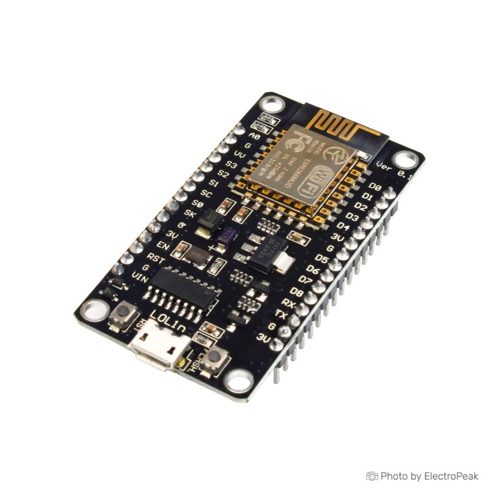
NodeMCU ESP8266 V3 Lua CH340G Wi-Fi Development Board
SAVE
As low as $1.9500
In stock
Only %1 left
SKU
COM-03-009
Product Variations:


Add an Accessory:


Ships in 2-3 business days, then:
Free delivery in 12-15 days by Tracked Economic Shipping on orders over $100.
Free delivery in 7-10 days by Express Shipping on orders over $300.
More shipping info

Shop with confidence Learn More
 ESP-201 ESP8266 WiFi Module Previous
NodeMCU ESP8266 V3 CH340G Review
The NodeMCU ESP8266 V3 Lua CH340G Wi-Fi Development Board combines an ESP8266-12E microcontroller with an integrated USB-to-serial interface for IoT prototypes, web applications, and robotics projects. It brings 2.4 GHz 802.11 b/g/n Wi-Fi, flash memory, and standard serial buses together on a single board for straightforward USB firmware deployment. It handles connected sensing and automation at 3.3V logic levels, but it is not built for direct 5V interfacing, high-current loads, multi-channel analog input, or multi-year battery operation.
To compare related form factors and configurations across the wider Wi-Fi hardware family, see our ESP8266 development boards.
Specifications of NodeMCU ESP8266 V3 Lua CH340G Wi-Fi Development Board
- Microcontroller: ESP8266 -12E (Tensilica Xtensa LX106)
- Operating Voltage: 3.3 Volt
- GPIO pins are not 5V compatible
- USB Driver: CH340G or CH340C
- Frequency: 2.4 Gigahertz (802.11 b/g/n)
- GPIO Pins: 17 pins (D0 to D8, RX/TX, A0, SDA, and SCL)
- Analog Input: A0 pin with 10-bit resolution
- Communication Interfaces: UART
- Communication Interfaces: I2C
- Communication Interfaces: SPI
- Flash Memory: 4 Megabytes (32Mbit)
- Regulator: LM1117 with 3.3V 500mA output
- Port: Micro USB or USB Type-C (optional)
- Dimensions: ---
NodeMCU ESP8266 V3 Specifications Explained
Board specifications determine both software capability and peripheral wiring. The table below shows how the key technical ratings of this NodeMCU V3 board affect practical project builds.
| Specification | Hardware Detail | Why It Matters for Your Build |
|---|---|---|
| Processor Core | Tensilica Xtensa LX106 (32-bit) | Executes lightweight networking tasks, local web servers, and sensor loops at clock speeds sufficient for local telemetry. |
| Wi-Fi Radio | 2.4 GHz 802.11 b/g/n | Connects directly to modern standard 2.4 GHz networks without external networking coprocessors, serving local HTTP or MQTT streams. |
| Flash Memory | 4 Megabytes (32Mbit) | Stores user sketch code, network credentials, and partitionable file storage systems (such as LittleFS) for embedded web pages and logs. |
| Buses (UART, I2C, SPI) | Hardware-supported serial interfaces | Allows direct interfacing with common digital hardware, including environmental sensors, OLED displays, and shift registers. |
| PWM Channels | Software-configurable pulse width modulation | Permits dimming low-current LEDs or sending control signals to motor drivers and servos via suitable external driving stages. |
| USB Port | Micro USB or USB Type-C (optional) | Provides single-cable programming and power; inspect the physical connector on the delivered unit before choosing your programming cable. |
| Form Factor Dimensions | Dimensions: --- | Physical enclosure dimensions and mounting holes should be confirmed against the physical unit before manufacturing tight enclosures. |
When planning your circuit topology and communication buses, consult our ESP8266 GPIO pinout guide to avoid bus overlap.
NodeMCU ESP8266 V3 GPIO, A0 and Power Limits
The board operates strictly at 3.3V logic, and its GPIO pins are not 5V compatible. Applying a 5V signal from a legacy sensor or micro-controller directly to an input pin risks damaging the ESP8266 chip. Use a bi-directional logic-level shifter or resistor divider between the devices when interfacing with 5V logic modules.
The hardware lists 17 physical pins spanning D0 to D8, RX, TX, A0, SDA, and SCL, but only 11 are general-purpose pins in everyday programming. GPIO6 through GPIO11 are wired internally to the onboard SPI flash memory chip; reassigning these pins in user code halts code execution or causes boot crashes. GPIO0, GPIO2, and GPIO15 also serve as hardware strapping pins during power-up:
- GPIO0: Must be pulled high for normal SPI flash boot; pulled low triggers programming boot mode.
- GPIO2: Must remain high during boot to ensure stable initialization.
- GPIO15: Must be pulled low during startup for normal operation.
- RX and TX (GPIO3 and GPIO1): Connect directly to the onboard USB-to-serial converter, causing serial communication conflicts if used as standard I/O during uploads.
For analog acquisition, the board exposes a single A0 pin backed by a 10-bit analog-to-digital converter. The bare ESP8266 silicon handles a 0 to 1.0V window, while this development board integrates an onboard resistor voltage divider, typically 220kΩ to 100kΩ, ahead of the chip pin. That shifts the safe measurement range at the board-level A0 header to 0–3.3V.
GPIO current capability is limited. Individual pins supply around 12 mA and sink around 20 mA, with cumulative GPIO draw best kept under 72 mA across the entire chip. Never connect relay coils, solenoids, DC motors, or multi-LED strings directly to GPIO headers. Drive them through external transistor stages, logic-level MOSFETs, or dedicated relay modules.
The onboard LM1117 regulator yields a nominal 3.3V 500mA output. That 500mA rating is a component ceiling governed by thermal dissipation. Wi-Fi transmission causes brief current spikes, so powering multiple external 3.3V sensors or display backlights from the board regulator can induce brownouts. For stable prototyping, isolate high-draw breakout circuits with an external breadboard power distribution module and route clean signal lines with jumper-wire connections.
For projects requiring extended battery runtimes, the fully assembled development board draws roughly 14–18 mA during software-commanded deep sleep. The bare ESP8266 processor can drop into microamp ranges, but the onboard USB bridge, voltage regulator, and supporting passives consume baseline current continuously. If your project needs a wider analog array and greater pin flexibility, consider an ESP32 board with more I/O and analog inputs, which provides 38 digital pins and 18 analog-capable channels.
NodeMCU ESP8266 V3 Setup and CH340G Compatibility
Set up the board by establishing a serial link between your computer and the onboard CH340G or CH340C bridge. Connect it with a verified, data-capable Micro USB cable, or the appropriate Type-C equivalent if your delivered unit features an optional Type-C jack. Charge-only cables deliver power without exposing a COM port.
Windows requires dedicated driver installation before it recognizes the bridge chip. Follow our CH340 driver installation guide to register the serial device correctly. On most modern Linux distributions and macOS versions, kernel drivers for the CH340 family load automatically.
To program the board within the Arduino ecosystem, follow these initial steps:
- Install the ESP8266 board core via the Arduino IDE Boards Manager.
- Select NodeMCU 1.0 (ESP-12E Module) under your board configuration menu.
- Choose the active serial port identified by your operating system device manager.
- Leave the upload speed at standard settings (such as 115200 baud); if connection dropouts occur, lower the baud rate.
- Compile and flash a basic LED blink routine targeting GPIO2 (internal blue LED) or send serial output to verify flashing integrity.
If uploads fail, confirm that no external wiring pulls GPIO0 low or ties down the serial RX/TX pins. Holding the onboard FLASH button while momentarily toggling the RESET button forces the microcontroller into bootloader mode if automated reset timing fails. For a complete programming walkthrough, refer to our Arduino IDE setup guide.
For tooling environments standardized on Silicon Labs drivers, choose the CP2102 NodeMCU USB interface. For modern interconnects and narrow breadboard margins, the Type-C NodeMCU with CP2102 combines the same core architecture with a slim footprint.
NodeMCU ESP8266 V3 Projects and IoT Uses
Within the ESP8266 and NodeMCU family, this platform provides an accessible base for network-linked automation. Its combination of processing overhead, standard networking libraries, and basic I/O supports a wide range of prototype categories.
- Connected Weather Stations: Interface 3.3V temperature, humidity, and barometric pressure sensors across I2C or SPI, then publish telemetry directly to cloud dashboards or web servers.
- Home Automation Relay Switches: Toggle lighting and appliances through remote HTTP or MQTT interfaces. This requires an optocoupled relay module rather than direct pin drive.
- IoT Environmental Telemetry: Sample single-point analog data, such as soil moisture or ambient light, using the 0–3.3V A0 pin and transmit data packets at regular wake intervals.
- Local Control Web Portals: Host a lightweight embedded web page inside the 4 MB flash memory to toggle digital states or review operational metrics from a local browser.
- Smart Device Prototyping: Validate embedded network logic and firmware behavior on a standard breadboard prototyping setup before fabricating custom circuit boards.
- Wi-Fi Lighting Drivers: Output software PWM signals to external logic-level MOSFETs to regulate 12V LED strips.
For bench development with less external sensor wiring, consider an ESP8266 board with built-in sensors and indicators, which incorporates an LDR, pushbuttons, and RGB LEDs on a stacked layout. Where visual feedback or battery management is required, the ESP8266 board with OLED status display integrates an onboard display alongside lithium cell charging management.
NodeMCU ESP8266 V3 Alternatives: Compact ESP8266 and ESP32 Boards
The NodeMCU V3 covers broad prototyping tasks, but its relatively wide physical footprint can obstruct side tie-points on common solderless breadboards. Board dimensions, antenna provisions, and processing architecture all affect enclosure fit.
| Model | Form Factor & USB | I/O & Sensing | Wireless Features | Primary Distinction |
|---|---|---|---|---|
| NodeMCU V3 (This Board) | Full-size; CH340G/C; Micro USB or Type-C | 17 header pins (11 usable GPIO), 1 ADC (0–3.3V) | 2.4 GHz Wi-Fi | Standard NodeMCU form factor with wide header spacing. |
| NodeMCU ESP8266 CP2102 | Standard; CP2102; Micro USB | 11 usable GPIO, 1 ADC | 2.4 GHz Wi-Fi | Direct equivalent using a CP2102 serial converter. |
| NodeMCU ESP8266 CP2102 (Type-C) | Slim profile; CP2102; USB Type-C | 11 usable GPIO, 1 ADC | 2.4 GHz Wi-Fi | Direct equivalent combining CP2102, Type-C, and narrow breadboard footprint. |
| WeMos D1 Mini ESP8266 | Ultra-compact; CH340; Micro USB | 11 GPIO, 1 ADC | 2.4 GHz Wi-Fi | Small footprint leaving exposed tie-points on compact breadboards. |
| WeMos D1 Pro Mini (Dual Antenna) | Ultra-compact; CP2104; Micro USB | 11 GPIO, 1 ADC | 2.4 GHz Wi-Fi | Features dual internal and external ceramic antenna connectors for RF enclosure routing. |
| ESP8266 Witty Cloud with Sensors | Two-piece stackable; CH340 | Standard ESP8266 lines | 2.4 GHz Wi-Fi | Includes an onboard LDR sensor, dual LEDs, and buttons for quick bench experiments. |
| NodeMCU ESP8266 with 0.91" OLED | Medium dev board; Micro USB | Standard ESP8266 lines | 2.4 GHz Wi-Fi | Integrates a 128x32 OLED display and lithium battery charge management circuitry. |
| Uno+WiFi R3 (ATmega328P + ESP8266) | Arduino Uno layout; CH340G | 14 digital (5V), 6 analog (ATmega) + ESP8266 | 2.4 GHz Wi-Fi | Dual-MCU approach offering 5V Arduino Uno shield compatibility alongside ESP8266 Wi-Fi. |
| ESP-WROOM-32 Wi-Fi Bluetooth | Full-size dual-core; CP2102 | 38 digital I/O pins, 18 ADC channels | Wi-Fi & Bluetooth 4.2 BLE | Upgrades to dual-core processing, Bluetooth stacks, and an extensive I/O count. |
Choose a compact ESP8266 board when a tight installation calls for an ultra-small profile. If an RF enclosure requires an external whip or patch, select an ESP8266 board with external antenna support. Projects needing BLE communication or multiple analog inputs call for an ESP32 Wi-Fi and Bluetooth board with the required peripheral headroom. For legacy shield stacks, an Uno-compatible board with Wi-Fi maintains 5V signaling across traditional headers.
NodeMCU ESP8266 V3 Accessories, FAQ and Buying Checklist
Make sure you have the supporting hardware needed to power, connect, and flash the board:
Required Accessories
- Computer with Compatible IDE: A workstation running the Arduino IDE, PlatformIO, or an equivalent toolchain with the ESP8266 core installed.
- CH340 Windows Driver: Necessary for Windows operating systems to establish communication with the CH340G or CH340C bridge.
- Data-Capable USB Cable: A functional data-capable Micro USB cable (or appropriate Type-C cable if your unit features a Type-C port) to carry serial data and 5V bus power.
Recommended Accessories
- Prototyping Breadboard: An MB-102 breadboard for organizing external connections during hardware debugging.
- Jumper Wire Set: Multi-length male/female jumper wires to bridge sensor modules to the board headers.
- External Power Regulation: A breadboard power distribution unit to feed power-hungry sensors without overloading the onboard LM1117 regulator.
- Logic Level Shifters: Bidirectional 3.3V-to-5V converters when reading from or signaling 5V digital devices.
- Switching Driver Stages: External transistors, MOSFETs, or optoisolated relay modules for loads exceeding 12 mA.
Optional Additions
- Environmental Sensors: Dedicated 3.3V-compatible modules for temperature, humidity, light, and barometric monitoring.
- External USB-to-TTL Adapter: For diagnostics or serial recovery if direct onboard USB communication is unavailable.
For builds requiring narrow pin-row clearance, inspect the NodeMCU pin-row spacing on the HW-389 variant. For designs that require defined module integration, verify the ESP-12E/12F board and PCB antenna listing.
Frequently Asked Questions
Do I need to install a CH340 driver for this NodeMCU ESP8266 V3 board?
Yes. Windows systems require manual CH340 driver installation before the board exposes a usable COM port. Most modern macOS and desktop Linux distributions support the CH340 interface natively without extra installation steps.
Can I connect 5V sensors directly to NodeMCU ESP8266 V3 GPIO pins?
No. The GPIO pins operate at 3.3V and are not 5V compatible. Exposing these pins directly to 5V signals can degrade or destroy the microcontroller; use a logic-level converter or voltage divider.
How many GPIO pins can I use on NodeMCU ESP8266 V3?
You can generally use 11 GPIO pins for application circuitry. While the board exposes 17 physical pins, six (GPIO6–GPIO11) connect to the onboard SPI flash memory and cannot be used, while GPIO0, GPIO2, and GPIO15 require specific logic levels during boot.
Is NodeMCU ESP8266 V3 A0 a 0–1V or 0–3.3V analog input?
The board-level A0 pin accepts a 0–3.3V input range. The internal ESP8266 silicon ADC measures a 0–1.0V range, while the development board integrates an onboard voltage divider that scales external signals up to 3.3V down to the chip limit.
Can NodeMCU ESP8266 V3 drive a relay or motor directly from a GPIO pin?
No. GPIO pins cannot source or sink the current needed to drive relay coils or motor windings. Pins are limited to roughly 12 mA source and 20 mA sink; always switch inductive or high-current loads using an external transistor, MOSFET, or driver module.
Why is my NodeMCU ESP8266 V3 not detected by Windows?
A missing CH340 driver or a charge-only USB cable is the most common cause. Verify that your USB cable transfers data, inspect Device Manager under Ports (COM & LPT), and ensure the CH340 driver has finished installing.
Is NodeMCU ESP8266 V3 suitable for a long-life battery project?
It is useful for battery-powered proof-of-concept tests, but not for multi-month battery deployments. The onboard voltage regulator and USB bridge draw roughly 14–18 mA continuously, preventing the assembled board from reaching true low-power deep-sleep states.
What is the difference between NodeMCU V3 and compact ESP8266 boards such as WeMos D1 Mini?
The NodeMCU V3 uses a broader board layout that spans most of a standard breadboard's width. Compact boards such as the D1 Mini compress the same core architecture into a smaller outline, leaving accessible connection rows on prototyping breadboards.
Purchase Decision Summary
- Ideal for: Hobbyists, students, and engineers assembling basic 3.3V Wi-Fi telemetry nodes, web-controlled outputs, MQTT clients, and standard Arduino IDE or Lua network prototypes.
- Maybe for: Breadboard prototyping where board width is manageable, or portable devices running from larger rechargeable packs where a 14–18 mA quiescent floor is acceptable.
- Avoid if: Your design requires 5V direct logic, Bluetooth capabilities, multiple analog inputs, high GPIO current draw, strict deep-sleep current ceilings, or external antenna jacks.
Buying Checklist
- Confirm your project logic runs at 3.3V or incorporate level shifters for 5V peripherals.
- Ensure 11 general-purpose GPIO pins and one analog input meet your circuit needs.
- Verify that your USB cable carries data lines, not power alone.
- Download the CH340 driver if programming from a Windows environment.
- Source a dedicated relay driver, transistor, or motor control board for high-current loads.
- Plan around the V3 physical width if building inside a tight enclosure or on a narrow breadboard.
- Step up to an ESP32 variant if your design demands Bluetooth or wider analog sensing.
| MCU/SoC | ESP8266-12E (Tensilica Xtensa LX106) |
|---|---|
| Product Family | NodeMcu |
| Architecture | Tensilica L106 32-bit |
| CPU Cores | 1 |
| Clock Speed (MHz) | 80 MHz |
| Flash | 4MB |
| SRAM | 80 KB |
| EEPROM | No |
| GPIO Pins | 17 |
| SPI interface Pins | 1 |
| I2C interface Pins | 1 |
| UART interface Pins | 1 |
| USB Ports | micro USB, USB Type-C |
| CAN Bus Support | No |
| Ethernet Support | No |
| ADC Channels | 1 |
| DAC Channels | No |
| PWM Channels | 10 |
| Operating Voltage (V) | 3.3V |
| GPIO Voltage (V) | 3.3V |
| GPIO Current (mA) | 12 |
| Active Current (mA) | 70mA - 170mA |
| Sleep Current (µA) | 20 |
| Wireless | Wi-Fi |
| Form Factor | compact |
| IDE Support | Arduino IDE, Lua, MicroPython |
| Input Voltage (V) | 5V |
| Antenna Type | Internal Antenna |
| Bluetooth Ver. | No |
Write Your Own Review

Please complete your information below to login.
Sign In
Create New Account