
Overview
In this tutorial, you’ll get to know the micropython programming and its platforms. At the end of this tutorial, you have learned about micropython, its applications, and its programming environment, and you can write a simple program using micropython’s practical libraries and functions.
What You Will Learn
- Introduction of MicroPython
- Introduction of MicroPython Programming Environment
- Programming ESP8266 with MicroPython
What is MicroPython?
Python is a very popular and practical high-level programming language. But in the case of programming the microcontrollers, other programming languages are more common than Python due to their high speed and proper processing power. MicroPython is an open source implementation of Python 3 that includes a small subset of Python standard libraries and is optimized for execution on microcontrollers with limited ROM and RAM. This version of the Python language is designed to have high speed and be used to communicate with some microcontrollers such as pyboard, Wipy, ESP32, ESP8266, and MicroBit.
Required Materials
Hardware Components
Software Apps
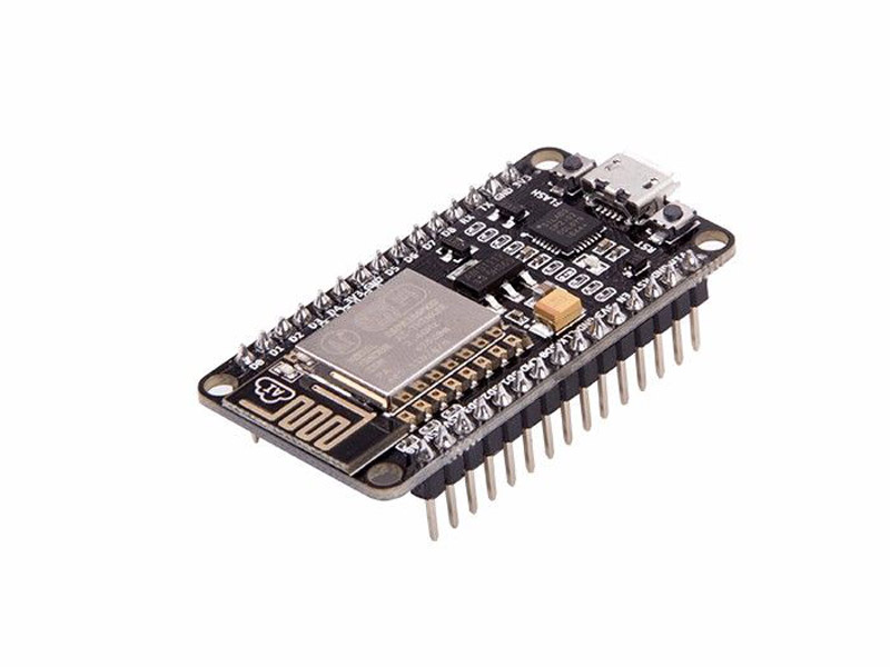
Why ESP8266?
Running MicroPython on ESP8266
As the first step to run the Python script on the ESP8266 module, you should download the MicroPython firmware for ESP8266 and upload it on the board.
You can download the ESP8266, or other microcontrollers firmware, from the following link:
http://micropython.org/download
After downloading the firmware, you should upload it on the board. In order to program the ESP8266 module you need the ESP8266Flasher, which you can download from the following link:
https://github.com/nodemcu/nodemcu-flasher
To enter the MicroPython programming environment or REPL(Read Evaluate Print Loop), you should use a serial terminal. We have used the Putty software to communicate with the ESP8266 on Windows. You can download the Putty software from the following link as well:
Now that you have downloaded the required software, you can program the ESP8266 as it is shown below:
Step 1. Choose the port which is connected to the ESP8266 module from the Operation menu.
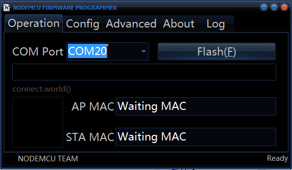

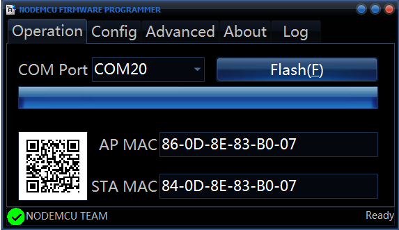
Step 3. Now click on Flash to install the firmware on your ESP8266 module.
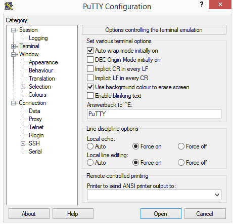
After installing the firmware, you should set the following configuration for the Putty software to enter the REPL.
Step 1. Choose the serial connection from the Putty connection type. Then choose the right COM and set the baud rate to 115200.
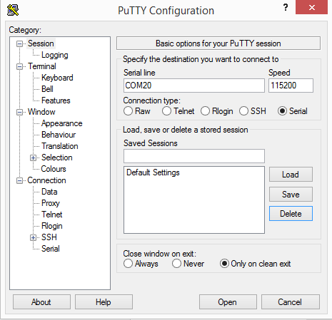
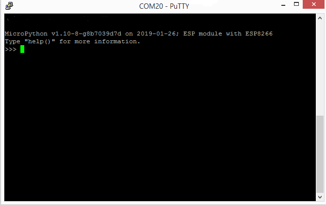
Step 2. Now click on the Open to get a REPL command prompt.
Cautiouns
MicroPython Programming through WebREPL
Follow the steps below to enter the WebREPL MicroPython programming environment:
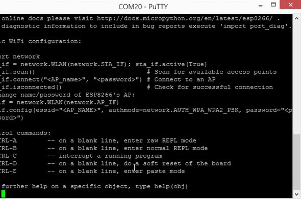
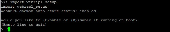
Step1. Open the http://micropython.org/webrepl/ in your browser. Then return to the command prompt and enter the following command.
>>> import webrepl_setupStep2. After running this command, you will be asked if you want to enable or disable the WebREPL. Enter E to enable the WebREPL.
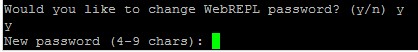
Step4. When you have done these steps, connect to the WiFi of the ESP module. Look for a WiFi network named micropython. The password is micropythoN by default.
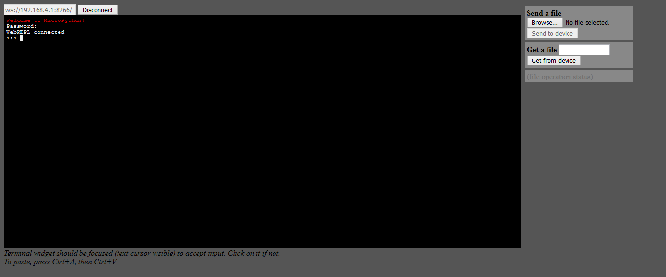
Step5. After connecting to the WiFi, return to the WebREPL page in your browser. Click on the Connect and enter the password you chose before.
Success
Project 1: Controlling an LED with MicroPython (Digital Control)
Turning the LED On and Off
Now we want to run a simple code to control an LED with the MicroPhyton. The ESP8266 has two LEDs on its board, connected to pins 2 and 16. To turn these LEDs on and off with MicroPayton, you need to control the input and output pins (GPIOs) of the module. You can use the machine library to do this.
>>> import machineNow you can use the functions of this library. The following command defines the pin2 of the module as an output pin:
>>> LED = machine.Pin( 2, machine.Pin.OUT)You can turn the LED that you have defined above, on and off using the following commands:
>>>LED.on()
>>>LED.off()
Or:
>>>LED.value(1)
>>>LED.value(0)
Blinking LED
Now we want to make a blinking LED by adding a key to the circuit. We need also the utime library as well as the machine library for this part.
Note
When you program a code on the ESP8266, it will continue running forever! In order to upload a new code on the module, you need to use the sys library to end the previous code that is still running.
>>> import machine
>>> import utime
>>> import sys
>>> LED = machine.Pin( 2, machine.Pin.OUT)
>>> Button = machine.Pin( 0, machine.Pin.IN, machine.Pin.PULL_UP)
By connecting a key to the pin 0, you will be able to exit the previous code by pressing the key.
>>>while True:
  >>>  if Button.value() == 0:
>>> sys.exit()exit() function ends the previous program. # Turn LED on and then off
>>> led.on()
>>> utime.sleep_ms(500)
>>>led.off()
>>> utime.sleep_ms(500)sleep_ms() function acts like delay function and generate a delay in milliseconds. Tip
For more information about MicroPython programming and its libraries and functions you can visit the following link:
Project 2: Controlling an LED with MicroPython (Analog Control)
Now we want to control the LED light with a potentiometer. To control the LED light, we use PWM. Connect the potentiometer to the ESP8266 module ADC pin. This pin reads the analog value of the potentiometer and converts it to a digital value between 0 and 1024. Then this digital value is sent as a PWM duty cycle to control the intensity of the LED light.
>>> import machine
>>> import utime
>>> import sys
>>> LED = machine.Pin( 2, machine.Pin.OUT)
>>> Button = machine.Pin( 0, machine.Pin.IN, machine.Pin.PULL_UP)
>>> ADCpin = machine.ADC(0)
>>> PWM=PWM(Pin(2))

>>>while True:
  >>>  if Button.value() == 0:
       >>> sys.exit()

>>>AnalogValue = adc.read()
>>>AnalogValue = AnalogValue * (3.3 / 4095)
>>>pwm.duty(AnalogValue)
>>>utime.sleep_ms(2)
What’s Next?
- Try to learn more function and do more complicated projects by visiting the MicroPython site

Comment (1)
I think that you have to do `from machine import Pin` now, to be able to use the Pin functions. At least thats what I have had to do, other wise it throws an error.