
Product added to cart

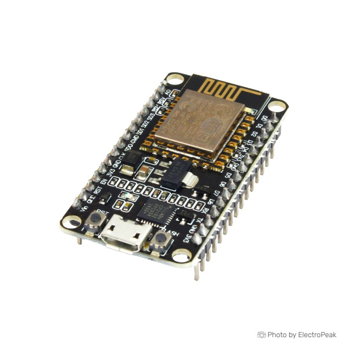
NodeMCU ESP8266 CP2102 Wi-Fi Development Board
$3.0100
In stock
SKU
COM-03-001
Volume discounts:
- +25 4 % $2.9000
- +100 6 % $2.8400
- +300 8 % $2.7800
- +500 10 % $2.7200
- +1000 11 % $2.6700
Product Variations:


Add an Accessory:


Ships in 2-3 business days, then:
Free delivery in 12-15 days by Tracked Economic Shipping on orders over $100.
Free delivery in 7-10 days by Express Shipping on orders over $300.
More shipping info

Shop with confidence Learn More

NodeMCU ESP8266 CP2102 Wi-Fi Development Board Review
The NodeMCU ESP8266 CP2102 combines an ESP8266 Wi-Fi module and a CP2102 USB-to-serial converter on one board, with direct USB programming and standard 2.4 GHz wireless networking. It is an accessible option for makers, students, and hobbyists building simple IoT prototypes, connected sensor nodes, and basic network-triggered controls in the Arduino IDE ecosystem. It is not intended for projects requiring Bluetooth, multiple analog inputs, broad GPIO availability, or ultra-low current consumption during battery-powered deep sleep.
For bench testing and programming, connect the board to your host computer with a separate data-capable Micro USB cable. To compare layouts and processing tiers, browse the wider range of ESP8266 development boards.
Specifications of NodeMCU ESP8266 CP2102 Wi-Fi Development Board
- Serial/USB Chip: CP2102
- Output Power(dBm):5 @802.11b Mode
- Flash Memory(Mb): 4
- Size (Length x Width x Height)(mm): 49 x 24 x 13
- Weight (g): 8
- ADC: 1 channel of 10-bit precision SAR ADC
- UART interfaces: 2 UART interfaces with support for flow control
- PWM outputs: 4 PWM pins to control things like motor speed or LED brightness
- SPI and I2C interfaces: Two SPI and one I2C interfaces for connecting various sensors and peripherals
- I2S interface: One I2S interface for adding sound to your project
- Clock speed: Up to 80 MHz
NodeMCU ESP8266 CP2102 Specifications Explained
Choose this board by matching its memory, interfaces, and physical size to your firmware requirements. The listed 4 Mb (512 KB) of onboard flash memory handles standard Arduino sketch binaries, basic web-server routines, and network libraries such as MQTT. It does not offer the storage needed for local file hosting, complex web dashboards, or heavy offline data logging.
| Specification | Listed Value | Why It Matters to Your Build |
|---|---|---|
| Processor Clock Speed | Up to 80 MHz | Provides sufficient processing bandwidth for handling network stacks, polling sensors, and running timing logic. Computationally heavy tasks or continuous digital signal processing will struggle on this single-core architecture. |
| Flash Memory | 4 Mb | Allocates storage for compiled code, Wi-Fi credentials, and small configuration files. Complex firmware using multiple heavyweight libraries may push this storage capacity. |
| Analog-to-Digital Converter | 1 channel, 10-bit SAR ADC | Restricts the board to reading a single analog sensor without adding an external I2C or SPI analog multiplexer. |
| Digital Bus Interfaces | 2 SPI, 1 I2C, 1 I2S | Permits bus-based communication with modern digital sensors, OLED displays, and audio DACs, reducing the need for raw GPIO toggling. |
| UART Interfaces | 2 interfaces with flow control | One UART is tied directly to the CP2102 bridge for serial flashing and debugging. Dedicated serial communication with external peripherals requires careful routing. |
| Physical Footprint | 49 x 24 x 13 mm (8 g) | Compact enough for project boxes, though the pin spacing spans most of the width of standard breadboards, often leaving no tie-points exposed on one or both sides. |
For peripheral breakout-board prototypes, a breadboard for connected components keeps off-board wiring organized. Need a smaller enclosure footprint? The compact ESP8266 board for tight enclosures is a smaller alternative that retains ESP8266 microcontroller support. More layouts and revisions are available among the ESP8266 development boards.
NodeMCU ESP8266 CP2102 Pinout, GPIO, and 3.3V Compatibility
The board breaks out 17 multipurpose GPIO pins, along with dedicated power, reset, and bus pins. Its electrical limits and special startup states matter: ignoring them can damage hardware or cause unexplained startup stalls.
All GPIO lines use strictly 3.3V logic. Connecting a 5V sensor output or 5V logic signal directly to any GPIO pin risks damaging the ESP8266 silicon. For 5V modules, use passive voltage dividers or bidirectional logic level shifters on the signal lines.
Several pins have strapping functions during bootup. GPIO0, GPIO2, and GPIO15 determine whether the microcontroller starts user firmware or enters the serial bootloader:
- GPIO0: Must be pulled high for normal flash boot. Pulling it low forces UART programming mode.
- GPIO2: Must remain pulled high during startup for successful boot.
- GPIO15: Must be pulled low during boot for internal flash execution.
Pushbuttons, pull resistors, or peripherals that hold these lines in the wrong state at power-on will prevent the board from booting your firmware. For detailed mappings and secondary multiplexed functions, consult the ESP8266 GPIO pinout reference.
Analog acquisition is limited to pin A0, which connects to the internal 10-bit SAR ADC. The bare ESP8266 processor accepts an analog input range of 0 to 1.0 V. Many NodeMCU boards include an onboard resistor divider to raise this threshold, but the exact board-level maximum voltage rating is not confirmed for this board. Do not feed more than 1.0 V into A0 unless you confirm an onboard divider or step down the signal externally.
Jumper wires for sensor connections make it easier to route signals cleanly to breadboards without stressing the header pins. Projects needing multiple analog channels, hardware Bluetooth, or greater processing bandwidth call for a different platform, such as an ESP32 board for more I/O and Bluetooth.
NodeMCU ESP8266 CP2102 Power, GPIO, and Boot Limitations
The board offers several power-input points: the Micro USB port, the 5V pin, and the VIN pin. General operating guidance recommends 4.5V to 9V on the external power pins. The VIN terminal accepts 5V or higher sources for the onboard linear voltage regulator, but avoid high input voltages because excess voltage is dissipated entirely as heat across that regulator.
Powering inductive or high-current loads directly from the board is a frequent cause of system resets and firmware instability. The onboard voltage regulator is sized for the ESP8266 module and modest logic sensors, not continuous current for mechanical relays, addressable LED strips, or DC motors. When these peripherals draw current during Wi-Fi transmission bursts, the 3.3V rail sags and triggers a brownout reset.
Prevent power-related crashes by using a dedicated separate breadboard power for peripherals. Keep a common ground between the peripheral power supply and the NodeMCU, and use the board's GPIO pins only to send control signals.
Battery deployment brings another trade-off. Although the ESP8266 chip itself supports deep-sleep states drawing microamps, this complete development board includes a linear regulator, a CP2102 USB bridge, and power LEDs that remain continuously energized. Board-level quiescent current is therefore significantly higher than the bare silicon rating, draining small battery packs quickly unless hardware alterations are made.
The onboard PCB trace antenna handles wireless range. Placement guidance recommends keeping the board within 10 meters of Wi-Fi access points for stable transmission, though real-world performance varies with wall density and transmitter power. There is no external antenna jack. For an off-board antenna inside a metal cabinet, use an alternative with external antenna support on a compact ESP8266 board.
NodeMCU is an open-source hardware reference, not a single proprietary factory build, so onboard component brands—such as regulator types or exact module revisions—can vary between production runs. For further architectural detail, review the ESP8266 GPIO pinout reference or compare designs in the ESP8266 development boards catalog.
NodeMCU ESP8266 CP2102 CP2102 Driver and Arduino IDE Setup
To connect the board to a development workstation, you need a computer, a data-capable Micro USB cable, and the Silicon Labs CP2102 USB-to-serial driver. Many operating systems include the driver natively. If your operating system does not assign a virtual COM port after connection, manually install the manufacturer CP2102 driver.
- Connect the board to your computer using a verified data cable. Confirm that an indicator LED lights up and that a new COM port appears in your operating system's device list.
- Launch the Arduino IDE and ensure the ESP8266 board package is installed through the Boards Manager.
- Navigate to Tools > Board and select NodeMCU 1.0 (ESP-12E Module).
- Under Tools > Port, choose the COM port assigned to the CP2102 bridge.
- Open a basic sketch, such as a serial print loop or the Blink example, and click Upload.
Sketch uploads rely on automatic hardware-reset circuitry controlled by the CP2102 lines. If the IDE reports that it cannot sync or connect to the ESP8266, use manual flashing: press and hold the Flash button, press and release the Reset button, then release the Flash button as the compiler finishes and the upload sequence begins.
For a board that will not flash or communicate, check these common points:
- Charge-only USB cable: Many standard cables contain only power conductors. Without data lines, no COM port can be created.
- Mismatched drivers: Do not install CH340 drivers for this hardware. Workflows that specifically rely on a CH340 environment need the CH340G NodeMCU USB-driver variant instead.
- External pin interference: Disconnect components wired to GPIO0, GPIO2, or GPIO15 during uploads to eliminate boot-state contention.
For a step-by-step walkthrough covering board-manager URLs, network libraries, and initial firmware examples, see the full Arduino IDE setup guide.
NodeMCU ESP8266 CP2102 vs CH340G and ESP8266 Alternatives
Within this board family, the main differences are the USB interface, physical layout, and integrated peripherals. Compared with the NodeMCU ESP8266 V3 with CH340G, this CP2102 board has the same primary processing, memory, and wireless capabilities; the functional difference is the USB-to-serial converter. The CP2102 bridge provides reliable serial communication across major desktop platforms, while the CH340G version suits users whose deployment systems are already configured around WCH drivers.
Several alternatives address specific physical or functional requirements outside the standard NodeMCU layout:
- Modern USB connector: The CP2102 NodeMCU board with Type-C replaces the legacy Micro USB connector with a Type-C port and uses a slimmer PCB that leaves pins accessible on both sides of a standard breadboard.
- Miniature enclosures: For small sensor pods, the compact ESP8266 board for tight enclosures drastically reduces total surface area.
- Integrated status displays: The ESP8266 board with integrated OLED display combines a 128x32 display with an onboard lithium battery charging circuit.
- Fast sensor prototyping: The ESP8266 board with built-in sensors and LEDs incorporates an LDR light sensor, RGB LEDs, and pushbuttons in a dual-board stacked configuration.
- Multitasking and Bluetooth: Applications that outgrow the single-core architecture can move to the ESP32 board for more I/O and Bluetooth, which provides dual-core processing, Bluetooth 4.2/BLE, and a substantial increase in GPIO and analog channels.
Compare more layouts and pinout configurations across the full range of ESP8266 development boards.
NodeMCU ESP8266 CP2102 Wi-Fi Board FAQ
What is the NodeMCU ESP8266 CP2102 board?
It is an open-source-style development board that combines an ESP8266 Wi-Fi microcontroller with a Silicon Labs CP2102 USB-to-serial converter. The design provides regulated 3.3V power and exposes the processor's GPIO pins, simplifying firmware development and connected-device prototyping.
Does this NodeMCU board work with Arduino IDE?
Yes. It is fully compatible with the Arduino IDE. After adding the ESP8266 board package, select NodeMCU 1.0 (ESP-12E Module) in the boards menu to compile and flash sketches.
Which driver does this NodeMCU board need: CP2102 or CH340?
This board requires the Silicon Labs CP2102 driver. CH340 drivers are for boards built with WCH bridge chips and will not establish communication with this hardware.
Do I need a Micro USB cable to program the NodeMCU ESP8266 CP2102?
Yes. Programming and serial monitoring require a standard Micro USB cable with internal data wires. Charge-only cables can power the board but cannot transmit data to your PC.
Can I connect 5V sensors directly to NodeMCU ESP8266 GPIO pins?
No. ESP8266 GPIO pins use 3.3V logic and are not rated for 5V inputs. Feeding 5V signals directly into the pins can damage the microcontroller; use level shifters or voltage dividers to step down the signal.
How many analog inputs does this NodeMCU board have?
The board provides one analog input channel on pin A0. Because the maximum board-level input voltage rating is unconfirmed for this board revision, verify or step down external signals above 1.0 V before connecting them.
Why does a NodeMCU ESP8266 board fail to boot after I connect a sensor?
GPIO0, GPIO2, and GPIO15 act as boot-mode selectors during power-up. An attached sensor or pull resistor that pulls GPIO0 or GPIO2 low, or GPIO15 high, prevents the chip from booting its application firmware.
Can this board power relays, LED strips, or motors directly?
No. Inductive and high-draw peripherals should never draw operating current through the board's 3.3V or VIN pins. Power these devices from an external power supply, use the NodeMCU GPIO only for logic signaling, and keep the grounds shared.
Is this NodeMCU board suitable for battery-powered deep-sleep sensors?
It is poorly suited to ultra-low-power battery applications without physical modification. The onboard linear regulator, CP2102 converter, and status LEDs continuously draw quiescent power, depleting battery reserves faster than a bare ESP8266 module would.
Does this NodeMCU ESP8266 board have Bluetooth?
No. The ESP8266 silicon supports only 2.4 GHz Wi-Fi. Projects needing Bluetooth Classic or BLE alongside Wi-Fi require a dedicated Wi-Fi and Bluetooth development board from the ESP32 family.
Should I choose this board or a WeMos D1 Mini?
Choose this NodeMCU board when you prefer a classic breakout profile with pre-soldered dual-row headers for direct jumper-wire connections. Choose the WeMos D1 Mini when physical space is constrained inside small project enclosures.
For more troubleshooting steps and coding examples, consult the full Arduino IDE setup guide. For external sensor modules, add jumper wires for sensor connections, or compare the complete family of ESP8266 development boards.
Purchase Decision Summary
- Ideal for: Makers, students, and technicians building single-analog Wi-Fi sensor nodes, MQTT publishers, Home Assistant integration endpoints, and basic IoT control switches via the Arduino IDE.
- Maybe for: Enclosed automation devices where external power supplies are accessible and the wider breadboard form factor is not a design barrier.
- Avoid if: Your system requires Bluetooth, multiple analog inputs, large volumes of concurrent GPIO, tight battery deep-sleep budgets, or onboard operation from high-current power rails.
Buying Checklist
- [ ] My application relies on 2.4 GHz Wi-Fi and does not require Bluetooth.
- [ ] One 10-bit analog input channel is sufficient for my project design.
- [ ] All connected sensors and peripherals operate at 3.3V logic or use voltage conversion.
- [ ] I have a verified data-capable Micro USB cable for programming.
- [ ] I can install the Silicon Labs CP2102 serial driver if prompted by my OS.
- [ ] Connected circuits will avoid pulling boot pins (GPIO0, GPIO2, GPIO15) into invalid startup states.
- [ ] High-current peripherals (relays, motors, LEDs) will be powered from a dedicated external power source.
- [ ] The 49 x 24 x 13 mm board footprint fits my enclosure and prototyping layout.
| MCU/SoC | ESP8266 |
|---|---|
| Product Family | NodeMcu |
| Architecture | Tensilica L106 32-bit |
| CPU Cores | 1 |
| Clock Speed (MHz) | 80 MHz |
| Flash | 4 MB |
| SRAM | 160 KB |
| GPIO Pins | 17 |
| SPI interface Pins | 2 |
| I2C interface Pins | 1 |
| UART interface Pins | 2 |
| USB Ports | 1 |
| Ethernet Support | No |
| ADC Channels | 1 |
| PWM Channels | 4 |
| Operating Voltage (V) | 3.3V |
| GPIO Voltage (V) | 3.3V |
| GPIO Current (mA) | 12 mA |
| Wireless | WiFi |
| Form Factor | NodeMcu V2 |
| IDE Support | Arduino IDE |
| Weight (g) | 8g |
| Input Voltage (V) | 4.5 - 9 V |
| Antenna Type | Internal Antenna |
| Bluetooth Ver. | No |
| Dimensions (mm) | 49 × 24 × 13 mm |
Write Your Own Review

Please complete your information below to login.
Sign In
Create New Account