
Product added to cart

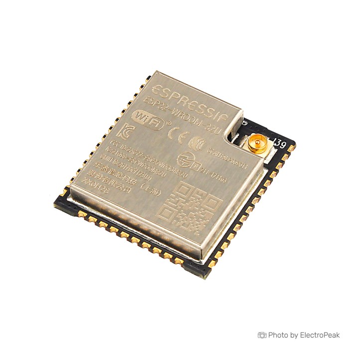
Espressif ESP32-WROOM-32U Module ( Wifi + Bluetooth)
SAVE
As low as $3.2500
In stock
Only %1 left
SKU
COM-03-092
Ships in 2-3 business days, then:
Free delivery in 12-15 days by Tracked Economic Shipping on orders over $100.
Free delivery in 7-10 days by Express Shipping on orders over $300.
More shipping info

Shop with confidence Learn More
 Espressif ESP32-WROOM-32 Module ( Wifi + Bluetooth) Previous
ESP32-WROOM-32U WiFi Bluetooth Module Review
The Espressif ESP32-WROOM-32U is a bare 2.4GHz Wi-Fi, Bluetooth, and BLE MCU module for custom electronics, robotics, and embedded carrier-board designs. Its defining feature is the U.FL connector, which lets you place a compatible external antenna away from the PCB or outside an RF-obstructive enclosure.
This module suits developers who can provide a carrier design, regulated 3.3V power, boot circuitry, and a programming path. It supports Wi-Fi 802.11b/g/n, Bluetooth 4.2, and BLE, but provides neither USB connectivity nor 5GHz Wi-Fi.
Specifications of ESP32-WROOM-32U WiFi Bluetooth Module
- Processor: Two low-power Xtensa 32-bit LX6 microprocessors
- ROM: 448 KBytes
- On-chip SRAM: 520 KBytes
- RTC SLOW SRAM: 8 KBytes
- RTC FAST SRAM: 8 KBytes
- EFUSE: 1 Kbit
- MAC storage: 256 bits
- Flash Memory: 4Mbit
- Flash Memory: 8Mbit
- Flash Memory: 16Mbit
- Networking protocols: IPv4
- Networking protocols: IPv6
- Networking protocols: SSL
- Networking protocols: TCP
- Networking protocols: UDP
- Networking protocols: HTTP
- Networking protocols: FTP
- Networking protocols: MQTT
- Interfaces: SD-card
- Interfaces: UART
- Interfaces: SPI
- Interfaces: SDIO
- Interfaces: I2C
- Interfaces: LED PWM
- Interfaces: Motor PWM
- Interfaces: I2S
- Interfaces: IR
- Interfaces: GPIO
- Interfaces: Capacitive touch sensor
- Interfaces: ADC
- Interfaces: DAC
- Interfaces: Hall sensor
- Interfaces: Temperature sensor
- Communication protocols: Wi-Fi 802.11b/g/n
- Communication protocols: Bluetooth 4.2
- Operating frequency: 2.4GHz
- RF output power: up to 20 dBm
- Operating voltage: 3.3V
- Dimensions: 18 × 25 mm
- Operating temperature: -40°C to +85°C
- Antenna connection: U.FL
The available interfaces suit connected sensor nodes, robotics telemetry, wireless actuators, Bluetooth peripherals, and compact custom ESP32 carrier boards. The listed application range also includes low-power sensor networks, voice encoding, music streaming, and MP3 decoding, provided the surrounding audio circuitry and memory requirements are designed appropriately.
For related ESP32 modules and development hardware, choose a complete development board when you need onboard USB, headers, buttons, and a regulator rather than a module intended for direct integration.
ESP32-WROOM-32U Specifications Explained
The two Xtensa 32-bit LX6 processors and 520 KBytes of on-chip SRAM provide the familiar ESP32-class platform for connected embedded firmware. Wi-Fi, Bluetooth 4.2 BR/EDR, Bluetooth LE, and the broad peripheral set let one carrier board handle wireless communication, sensor interfaces, PWM outputs, serial devices, and audio-oriented I2S connections.
| Specification area | Why it matters |
|---|---|
| Dual-core Xtensa LX6 processors | Supports concurrent embedded tasks such as application logic, communication handling, and peripheral control within the ESP32 software ecosystem. |
| 2.4GHz Wi-Fi 802.11b/g/n | Works with 2.4GHz Wi-Fi networks. It is not a 5GHz Wi-Fi module, so it will not meet projects that require a 5GHz-only network. |
| Bluetooth 4.2 BR/EDR and Bluetooth LE | Bluetooth Classic can suit legacy-device and some audio-oriented requirements, while BLE suits lower-power peripherals and sensor communication. |
| UART, SPI, I2C, I2S, SDIO, PWM, ADC, DAC, GPIO and touch interfaces | These functions need to be allocated around the pins exposed by the module, the carrier-board routing, flash-connected pins, and boot strapping requirements. |
| IPv4, IPv6, SSL, TCP, UDP, HTTP, FTP and MQTT | These are firmware and software-stack capabilities, not separate physical hardware ports. Their use depends on the selected SDK, libraries, memory allocation, and application configuration. |
| RF output power: up to 20 dBm | RF output depends on operating mode, channel, modulation, antenna, RF layout, and enclosure. It is not a guaranteed range figure. |
The listed Hall sensor and temperature sensor remain feature assertions for this module family, but practical availability depends on the exact chip revision and software stack. Do not reserve either feature in a design until it has been verified on the supplied module.
Confirm flash capacity before creating firmware partitions, OTA update slots, or a filesystem layout. The stated 4Mbit, 8Mbit, and 16Mbit values do not establish the capacity of this board; confirm the shipped value in MB or bytes. In particular, 16Mbit is not 16MB.
Begin hardware allocation with an ESP32 pin planning reference, then verify the carrier layout against the module documentation. During prototyping, the ESP-32S Matching Adapter Board for ESP32-WROOM exposes the bare module on a more practical carrier.
For a project that specifically requires Wi-Fi 6, Zigbee, Thread, 16MB flash, or USB boot support, the ESP32-C6-WROOM-1 with 16MB Flash is a better fit. It is a different module family, not an established drop-in replacement for the ESP32-WROOM-32U.
ESP32-WROOM-32U External Antenna, Power and Bare-Module Requirements
The ESP32-WROOM-32U uses a U.FL external antenna connection and has no onboard PCB antenna. The module itself does not include an external antenna, so plan for a compatible antenna unless package contents are confirmed separately.
A suitable starting point is the 2.4GHz 4DB IPEX WIFI Antenna. Confirm that any antenna, cable, or pigtail uses the U.FL/IPEX-generation-1 connector family; do not assume visually similar MHF4 connectors are interchangeable.
External antenna placement helps when electronics sit inside a metal, shielded, or RF-obstructive enclosure. It does not guarantee longer range. Antenna choice, cable loss, 50Ω routing, ground clearance, enclosure materials, placement, and real-world validation all affect RF performance.
The listed operating voltage is 3.3V. For the bare module, use the recommended 3.0–3.6V range and an external supply designed to provide at least 0.5A; direct 5V connection to the module supply is not compatible. Local decoupling capacitors and short, low-resistance power routing help prevent radio-related voltage drops and brownout resets.
This is a bare module, not a USB development board. A workable build needs a carrier PCB or adapter, regulated power, EN/reset handling, GPIO0 boot control, and a programming interface with compatible 3.3V logic levels. The ESP-32S Matching Adapter Board for ESP32-WROOM offers a useful adapter format, while the CP2102 USB to TTL UART Serial Convertor Module provides a UART programming path.
Required hardware
- External antenna: A 2.4GHz 4DB IPEX WIFI Antenna or another verified 2.4GHz, 50Ω U.FL/IPEX-generation-1-compatible antenna.
- Carrier or breakout: A carrier PCB or the ESP-32S Matching Adapter Board for ESP32-WROOM for mounting and access to module connections.
- Power supply: A regulated 3.0–3.6V supply with sufficient transient capability for the recommended at-least-0.5A external supply requirement.
- Boot and reset circuitry: EN/reset and GPIO0 control for a permanent carrier design.
- Programming interface: The CP2102 USB to TTL UART Serial Convertor Module or another compatible 3.3V-logic UART programming method.
Total build cost includes the antenna, carrier or adapter, programmer, and power-design components; no product or accessory price is specified here. Once the hardware is ready, the ESP32 Arduino setup guide covers installation on Windows, macOS, and Linux.
For low-power BLE, Zigbee 3.0, Matter, or HomeKit projects that do not require Wi-Fi, consider the ESP32-H2-MINI-1 BLE & Zigbee Module, a more appropriate module family.
ESP32-WROOM-32U Limitations and Design Warnings
The official ESP32-WROOM-32U documentation marks the module Not Recommended for New Designs (NRND). It can remain appropriate for an existing validated design or a low-volume project, but a long-lived new product should validate availability, supply continuity, and an alternative before commitment.
Flash information is the main purchasing uncertainty. The specifications list 4Mbit, 8Mbit, and 16Mbit entries without identifying the shipped configuration, so confirm the actual capacity in MB or bytes before ordering or planning OTA and filesystem partitions.
Dimensions also need verification before PCB fabrication. The stated dimensions are 18 × 25 mm, while official ESP32-WROOM-32U documentation reports approximately 18 × 19.2 × 3.1–3.2 mm. Confirm the actual seller-stock module footprint, dimensions, and land pattern before finalizing a carrier board.
- No 5GHz Wi-Fi: This is a 2.4GHz Wi-Fi module.
- No listed PSRAM: Standard ESP32-WROOM-32U documentation does not list PSRAM, so memory-heavy display, buffering, and audio applications require careful memory planning.
- RF layout matters: Use suitable 50Ω RF routing, connector clearance, antenna placement, ground clearance, and enclosure-aware validation.
- Traceability is not specified: Module marking, lot code, silicon revision, manufacturing date, authorization status, and supply-chain documentation are not provided.
One uncorroborated report described a networking issue, but it does not establish a product-wide defect. There is no stated failure-rate data or meaningful independent review history for this exact version.
For a different external-antenna memory tier with stated 16 MB integrated SPI flash, evaluate the ESP32-WROVER-IB with Ipex antenna. It is part of the WROVER family, which is associated with PSRAM-oriented applications, although its supplied product information does not state the PSRAM quantity.
Use an external antenna such as the 2.4GHz 4DB IPEX WIFI Antenna only after confirming connector fit. For carrier-board routing, follow an ESP32 safe GPIO selection guide rather than assigning pins solely by peripheral labels.
ESP32-WROOM-32U vs ESP32-WROVER-IB and ESP32-C6-WROOM-1
| Module | Antenna arrangement | Flash information | Wireless and processor information | Best fit |
|---|---|---|---|---|
| ESP32-WROOM-32U | U.FL external antenna connection | 4Mbit, 8Mbit, and 16Mbit values are listed; exact shipped capacity is unconfirmed | 2.4GHz Wi-Fi 802.11b/g/n, Bluetooth 4.2 BR/EDR, Bluetooth LE, dual-core Xtensa LX6 | Established ESP32-class custom carrier boards requiring external antenna placement |
| ESP32-WROVER-IB with Ipex antenna | Ipex external antenna connector | 16 MB integrated SPI flash stated | Dual-mode Bluetooth stated | External-antenna designs needing a different memory tier |
| ESP32-C6-WROOM-1 with 16MB Flash | Not stated | 16MB QSPI flash stated | Wi-Fi 6, Zigbee, Thread, RISC-V processor, USB boot support | Projects specifically requiring Wi-Fi 6, Zigbee, Thread, 16MB flash, or USB boot |
Choose the ESP32-WROOM-32U when an established ESP32 classic design and flexible external antenna placement are the central requirements. The trade-off is integration work: the carrier board must provide power, programming, reset, boot control, and RF-aware layout.
The ESP32-WROVER-IB with Ipex antenna suits designs that need an external antenna plus stated 16 MB integrated SPI flash. Choose the ESP32-C6-WROOM-1 with 16MB Flash when newer Wi-Fi 6 and 802.15.4 requirements are part of the design; it should not be treated as a drop-in replacement.
Browse other ESP32 modules when the project is better served by a different wireless family, memory tier, or module architecture.
ESP32-WROOM-32U Setup and Pin Compatibility
The module has no USB connector or USB-to-UART bridge. Before flashing firmware, the carrier must provide regulated 3.3V power, ground, a compatible antenna, UART connections, EN/reset handling, and GPIO0 boot control.
First-power-on verification
- Confirm the printed module marking, U.FL connector, and flash marking before soldering or configuring partitions.
- Mount the module on a suitable carrier or adapter board.
- Connect a regulated 3.3V supply within the 3.0–3.6V recommended range, designed for at least 0.5A.
- Attach a compatible 2.4GHz U.FL/IPEX-generation-1 antenna.
- Connect GND, TXD0, RXD0, EN/reset control, GPIO0 boot control, and a 3.3V-logic USB-to-UART adapter.
- Hold GPIO0 low during reset to enter UART download mode.
- Flash a minimal serial-output or GPIO test.
- Confirm stable serial boot output or the expected GPIO behavior before adding sensors, motors, Wi-Fi application logic, or Bluetooth peripherals.
ESP-IDF, Arduino-ESP32, esptool, and MicroPython workflows are available for the ESP32 family. Board selection, UART wiring, reset behavior, and pin assignments still depend on the carrier design rather than on a standard USB development-board layout.
Pin and boot considerations
- GPIO6 through GPIO11 are connected to integrated flash and should not be used as normal peripheral I/O.
- GPIO0, GPIO2, GPIO5, GPIO12/MTDI, and GPIO15/MTDO are boot strapping pins. Do not force them into incompatible states during reset.
- Use a USB-to-UART adapter with compatible 3.3V logic levels. A 5V UART signal can damage or destabilize a 3.3V module interface.
Common startup faults
- No serial port: The module has no USB interface; verify the USB-to-UART adapter and its driver.
- Upload timeout: Check TX/RX wiring, ground, GPIO0 download-mode control, and EN/reset timing.
- Brownout reset or boot loop: Check supply voltage, transient current capability, decoupling, and power routing.
- No wireless signal: Confirm that the antenna is attached and that the connector generation matches.
- Weak RF performance: Check antenna placement, cable loss, enclosure effects, RF routing, ground clearance, and 2.4GHz network conditions.
The CP2102 USB to TTL UART Serial Convertor Module is suitable for the programming connection. The CH340G USB to TTL Converter is an alternative, and the Breadboard Jumper Wire Kit - 140 Pieces helps with prototype power and UART wiring.
For software installation, use the Arduino IDE ESP32 board installation guide. Check the ESP32 Pinout Reference before committing peripheral assignments.
ESP32-WROOM-32U FAQ and Buying Checklist
Does the ESP32-WROOM-32U include an antenna?
No. The module uses a U.FL external antenna connection, and the module itself does not include an external antenna. Plan for a compatible 2.4GHz antenna unless package contents are confirmed separately.
Is the ESP32-WROOM-32U a complete development board?
No. It is a bare module without a USB connector or USB-to-UART bridge, so it needs a carrier or adapter, regulated power, programming hardware, and boot/reset handling.
Can I power the ESP32-WROOM-32U directly from 5V?
No. The module operates at 3.3V, with a recommended operating range of 3.0–3.6V and an external supply recommendation of at least 0.5A. A separate carrier may accept 5V through its own regulator, but that does not apply to the bare module supply pins.
Does the ESP32-WROOM-32U support 5GHz Wi-Fi?
No. It supports 2.4GHz Wi-Fi 802.11b/g/n only.
Does the ESP32-WROOM-32U support Bluetooth Classic and BLE?
Yes. Bluetooth support includes Bluetooth 4.2 BR/EDR and Bluetooth LE.
How much flash memory does this ESP32-WROOM-32U have?
The exact shipped flash capacity is not confirmed. The stated 4Mbit, 8Mbit, and 16Mbit values are inconsistent, so confirm capacity in MB or bytes before planning OTA updates or filesystem partitions; 16Mbit is not 16MB.
Does the ESP32-WROOM-32U include PSRAM?
No PSRAM is listed in standard ESP32-WROOM-32U documentation. For an external-antenna design needing a different memory tier, evaluate the ESP32-WROVER-IB with Ipex antenna.
Which antenna fits the ESP32-WROOM-32U U.FL connector?
Use a compatible 2.4GHz, 50Ω antenna with the U.FL/IPEX-generation-1 connector family or a matching pigtail. Do not assume MHF4 connectors are interchangeable.
Do I need a USB-to-TTL adapter to program the ESP32-WROOM-32U?
Yes, unless the carrier provides another programming interface. Firmware flashing needs a USB-to-UART or equivalent path, correct UART wiring, EN/reset handling, and GPIO0 boot control.
Can I use GPIO6 through GPIO11 as normal I/O?
No. GPIO6 through GPIO11 are connected to integrated SPI flash and are not recommended for normal peripheral use.
Is the ESP32-WROOM-32U suitable for a new production design?
Evaluate it carefully before using it in a long-lived new design. Official documentation marks the module NRND, so validate supply availability and an alternative before committing to production.
Purchase decision summary
- Ideal for: Custom ESP32 carrier boards that need Wi-Fi, Bluetooth Classic, BLE, compact MCU integration, and an antenna positioned away from the PCB or outside an RF-obstructive enclosure.
- Maybe for: Experienced makers comfortable adding a 3.3V supply, adapter board, USB-to-TTL programmer, boot circuitry, and compatible U.FL antenna.
- Avoid if: You need USB plug-and-play setup, an included antenna, direct 5V input, 5GHz Wi-Fi, confirmed PSRAM, confirmed flash capacity, or a preferred option for a long-lived new production design.
Buying checklist
- ✓ I need a bare ESP32 module rather than a complete development board.
- ✓ I have a regulated 3.0–3.6V supply with sufficient capacity for the recommended at-least-0.5A external supply requirement.
- ✓ I have a compatible 2.4GHz U.FL/IPEX-generation-1 antenna or pigtail.
- ✓ I have a carrier PCB, breakout, or adapter board for the module.
- ✓ I have a 3.3V-logic USB-to-UART programmer or another flashing method.
- ✓ My carrier design includes EN/reset and GPIO0 boot control.
- ✓ My pin plan avoids GPIO6–GPIO11 and accounts for strapping pins.
- ✓ I do not need 5GHz Wi-Fi.
- ✓ I do not need confirmed PSRAM.
- ✓ I have confirmed actual flash capacity in MB or bytes before planning OTA or filesystem partitions.
- ✓ I have verified actual seller-stock dimensions before committing to a PCB footprint.
- ✓ I have considered NRND status and validated an alternative for a new long-life product.
For the required RF and mounting hardware, pair this module with the 2.4GHz 4DB IPEX WIFI Antenna and the ESP-32S Matching Adapter Board for ESP32-WROOM.
Buyers who need only basic Wi-Fi networking rather than ESP32 Bluetooth/BLE support or dual-core processing can take a different approach with the ESP-12E ESP8266 Module or the ESP-12S ESP8266 Module. For broader module options, see the ESP32 category.
| MCU/SoC | ESP32-WROOM-32U |
|---|---|
| Product Family | ESP32 |
| Architecture | Tensilica Xtensa LX6 |
| CPU Cores | Dual-core |
| Clock Speed (MHz) | Up to 240 MHz |
| Flash | 4Mbit,16Mbit |
| SRAM | 520 KB |
| GPIO Pins | GPIO |
| SPI interface Pins | 3 |
| I2C interface Pins | 2 |
| UART interface Pins | 3 |
| USB Ports | No |
| CAN Bus Support | Yes (Controller) |
| Ethernet Support | No |
| ADC Channels | 18 |
| DAC Channels | 2 |
| PWM Channels | 16 |
| Timers Count | 4 |
| Operating Voltage (V) | 3.3V |
| GPIO Voltage (V) | 3.3V |
| GPIO Current (mA) | 12mA |
| Sleep Current (µA) | 5 |
| Wireless | Bluetooth, Wi-Fi |
| Form Factor | Module |
| IDE Support | Arduino IDE, MicroPython, Espressif IoT Development Framework (ESP-IDF) |
| Antenna Type | External IPEX/IPX |
| Bluetooth Ver. | 4.2 |
| Operating Temp (°C) | -40°C to +85°C |
| Dimensions (mm) | 18 × 25 mm |
Write Your Own Review

Please complete your information below to login.
Sign In
Create New Account