
Overview
Welcome to the comprehensive guide to the ESP32 pinout. The ESP32 microcontroller is equipped with 48 pins, each serving multiple functions. However, not all pins are readily accessible on every ESP32 development board, and certain pins may have usage restrictions. This article aims to provide a clear and concise reference for understanding the pin configurations and functionalities of the ESP32, offering valuable insights into which pins to utilize and which to avoid for your projects. Whether you’re a beginner or an experienced developer, this guide will help you navigate the intricacies of the ESP32 pinout with ease
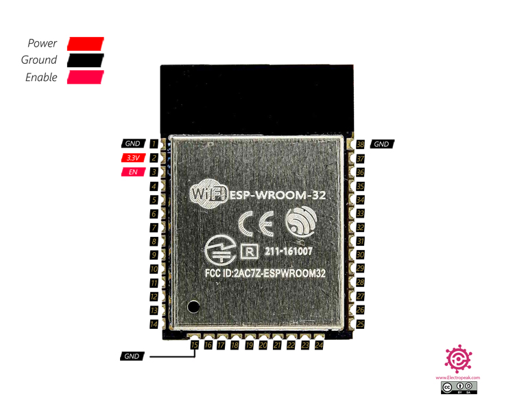
The ESP-WROOM-32 Pinout
Various types of ESP32 microcontrollers are available in the market. The one extensively covered in this tutorial is the ESP-WROOM-32, also known as WROOM32. This microcontroller is widely acclaimed and commonly used in numerous ESP32-based development boards such as the ESP32 DEVKIT. Even if you are utilizing a different ESP32 microcontroller-based development board, this tutorial remains relevant, as other ESP32 microcontrollers share similar pin configurations to the WROOM32.
Below, you will find a comprehensive pinout diagram of the ESP32-WROOM-32, which will be elaborated on in detail.
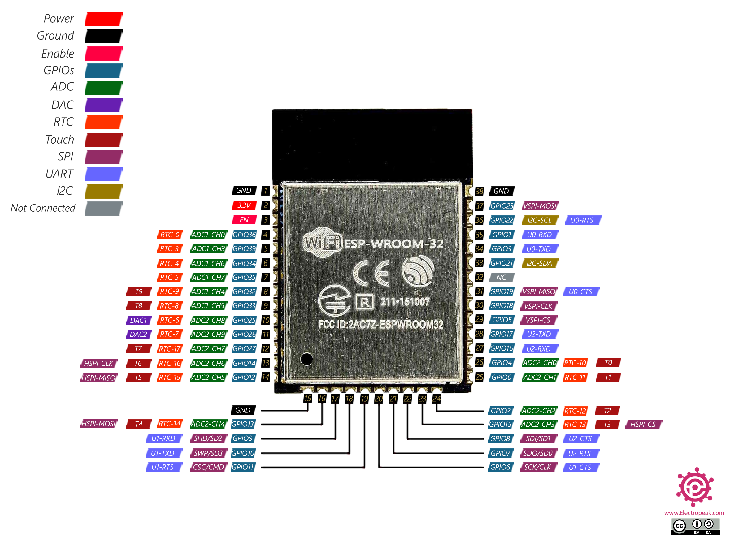
The ESP32 Pins & Peripherals
The ESP32 microcontroller has the following pins :
- 18 12-bit ADC pins
- 2 8-bit DAC pins
- 3 SPI interfaces
- 2 I2C interfaces
- 3 UART interfaces
- 16 PWM channels
- 2 I2S interfaces
- 10 touch pins
The ESP32 has the following GPIO (General Purpose Input/Output) pins.
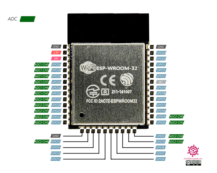
ESP32 ADC Pins
There are a total of 18 12-bit ADC (Analog to Digital Converter) pins in the ESP32 microcontroller. Being a 12-bit ADC means that it can convert the input voltage to a number between 0 and 4095. 0 for 0V input and 4095 for 3.3V input.
These 18 pins are as follows.
- ADC1-CH0 (GPIO 36)
- ADC1-CH1 (GPIO 37)
- ADC1-CH2 (GPIO 38)
- ADC1-CH3 (GPIO 39)
- ADC1-CH4 (GPIO 32)
- ADC1-CH5 (GPIO 33)
- ADC1-CH6 (GPIO 34)
- ADC1-CH7 (GPIO 35)
- ADC2-CH0 (GPIO 4)
- ADC2-CH1 (GPIO 0)
- ADC2-CH2 (GPIO 2)
- ADC2-CH3 (GPIO 15)
- ADC2-CH4 (GPIO 13)
- ADC2-CH5 (GPIO 12)
- ADC2-CH6 (GPIO 14)
- ADC2-CH7 (GPIO 27)
- ADC2-CH8 (GPIO 25)
- ADC2-CH9 (GPIO 26)
Note
Pay attention that channels related to the ADC2 interfere with the Wi-Fi. If the Wi-Fi of the ESP32 is running, you better use the ADC1 pins.
DAC Pins
The ESP32 includes 2 8-bit DAC (Digital to Analog) pins. The 8-bit resolution means that these converters can produce a voltage between 0 and 3.3V with the accuracy of 3.3/256 volts.
These 2 pins are as follows.
- DAC1 (GPIO 25)
- DAC2 (GPIO 26)

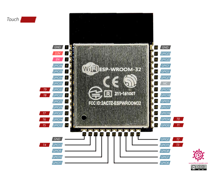
Capacitive Touch GPIOs
In addition to their touch sensor functionality, the ESP32’s 10 capacitive touch pins can wake up the microcontroller from deep sleep. To learn more about the ESP32 deep sleep mode, refer to our “ESP32 Deep Sleep” tutorial.
The 10 touch pins of the ESP32 microcontroller are as follows.
- T0 (GPIO 4)
- T1 (GPIO 0)
- T2 (GPIO 2)
- T3 (GPIO 15)
- T4 (GPIO 13)
- T5 (GPIO 12)
- T6 (GPIO 14)
- T7 (GPIO 27)
- T8 (GPIO 33)
- T9 (GPIO 32)
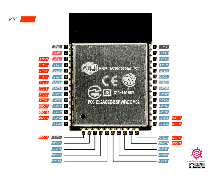
ESP32 RTC Pins
The ESP32 microcontroller has a total of 16 RTC (Real Time Clock) pins, which are mainly used in the ESP32 already mentioned deep sleep mode. These pins can also wake up the ESP32 from deep sleep.
The RTC pins of the ESP32 microcontroller are as follows.
- RTC_GPIO0 (GPIO 36)
- RTC_GPIO3 (GPIO 39)
- RTC_GPIO4 (GPIO 34)
- RTC_GPIO5 (GPIO 35)
- RTC_GPIO6 (GPIO 25)
- RTC_GPIO7 (GPIO 26)
- RTC_GPIO8 (GPIO 33)
- RTC_GPIO9 (GPIO 32)
- RTC_GPIO10 (GPIO 4)
- RTC_GPIO11 (GPIO 0)
- RTC_GPIO12 (GPIO 2)
- RTC_GPIO13 (GPIO 15)
- RTC_GPIO14 (GPIO 13)
- RTC_GPIO15 (GPIO 12)
- RTC_GPIO16 (GPIO 14)
- RTC_GPIO17 (GPIO 27)
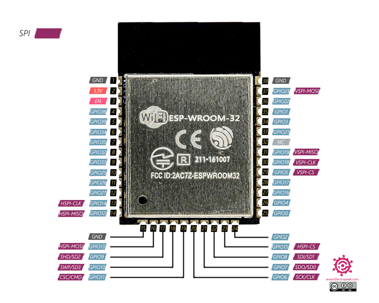
ESP32 SPI Pins
The ESP32-WROOM-32 microcontroller provides 3 default SPI interfaces. One of them is designed for the communication between the ESP32 and the SPI flash memory, so, it’s recommended not to use. The pin mapping related to this SPI interface is as follows:
- SCK/CLK (GPIO 6)
- SDO/SD0 (GPIO 7)
- SDI/SD1 (GPIO 8)
- SHD/SD2 (GPIO 9)
- SWP/SD3 (GPIO 10)
- CSC/CMD (GPIO 11)
Apart from the dedicated SPI interface, the ESP32 offers two additional SPI interfaces: HSPI (Hardware SPI) and VSPI (Virtual SPI). The table below shows the pins assigned to these interfaces. Note that you can define any other ESP32 pins as SPI if necessary.
| SPI | MISO | MOSI | CLK | CS |
|---|---|---|---|---|
| HSPI | GPIO 12 | GPIO 13 | GPIO 14 | GPIO 15 |
| VSPI | GPIO 19 | GPIO 23 | GPIO 18 | GPIO 5 |
Note
Note that you’re not limited to using the two interfaces introduced above, and you can define any other pins of the ESP32 as SPI.
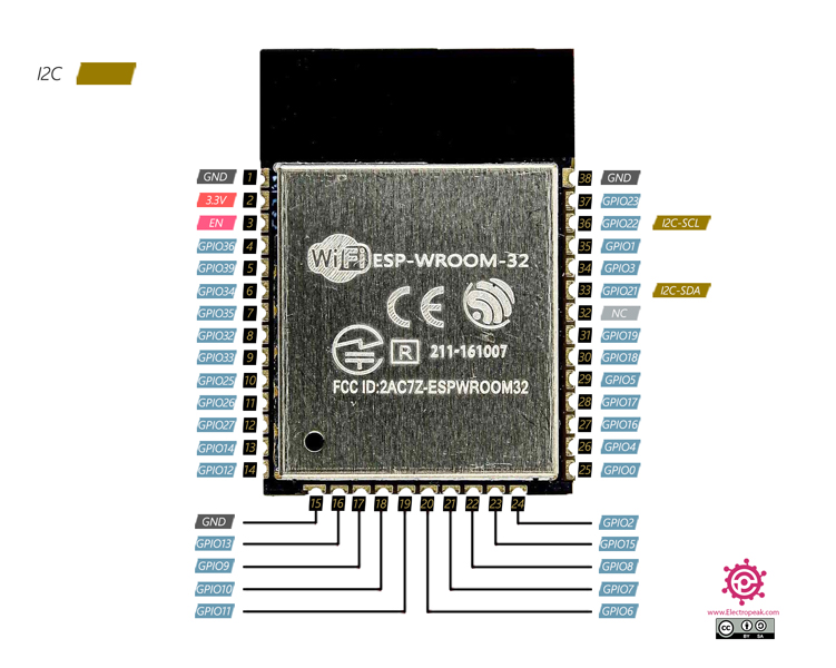
ESP32 I2C Pins
As mentioned in ESP32 pinout, the ESP32 has 2 internal I2C channels and also a default pair of pins for the I2C communication protocol. And just like SPI, you can define any other pins of the ESP32 as I2C, if required.
The default I2C pins of ESP32 are as follows:
- SDA (GPIO 21)
- SCL (GPIO 22)
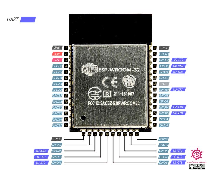
ESP32 UART Pins
The ESP32 features 3 default UART interfaces, and you can define additional pins as UART interfaces in your code.
You can see the pins related to these 3 UART interfaces.
| UART | RXD | TXD | RTS | CST |
|---|---|---|---|---|
| UART0 | GPIO 1 | GPIO 3 | GPIO 22 | GPIO 19 |
| UART1 | GPIO 9 | GPIO 10 | GPIO 11 | GPIO 6 |
| UART2 | GPIO 16 | GPIO 17 | GPIO 7 | GPIO 8 |
ESP32 PWM Pins
The ESP32 contains a PWM controller circuit that can be used to generate PWM signals in 16 different channels and control them independently.
To generate a PWM signal, you first need to set the following values in your code.
- Signal frequency
- Pulse width
- PWM channel
Then, you can set this PWM signal as the output of any of the ESP32 GPIO pins that are capable of being set as an output. The GPIO pins 34-39 cannot be set as output, so you can’t use them to get PWM signals.
Interrupt Pins
You can use all GPIO pins as an interrupt.
Power Supply Pins
The pins related to power supply are as follows.
3.3V Pin
The pin number 2 of the ESP32 microcontroller, as depicted in the image above, is its main power supply pin. Forasmuch as the microcontroller operates at 3.3V logic level, it’s important to prepare an accurate power supply for the microcontroller to minimize the chances of damage to the chip.
GND Pins
The pins number 1, 15 and 38 of this microcontroller are the GND pins. When powering the microcontroller, it’s necessary to connect them all to the ground of the external power supply.
EN Pin
The pin number 3 is the EN (Enable) pin of the ESP32 microcontroller. This pin is so called “Active High” and needs to be connected to a high logic level (3.3V) for the microcontroller to operate.
What’s Next?
Once you’ve completed this tutorial, take on exciting challenges related to ESP32 pins:
- Learn to set up a touch sensor pin on the ESP32 and control an LED using its input.
Now that you have gained a comprehensive understanding of ESP32 pinout, it’s time to put your knowledge into practice. Start exploring the endless possibilities for your IoT projects! If you have any questions or need further assistance, feel free to ask in the comments below.

Comments (10)
RX and TX pins are swaped!
GPIO1 is TX;
GPIO3 is RX;
Hi Dear
if you connect any device with serial port you should connect Device TX pin to ESP RX pin and Device RX pin to ESP TX pin.
regards.
There are only 6 ADC’s for ADC 1, the other two do not seem to be pinned out… If this is different please let me know, but I cannot find them.
Hi
the ESP32 board has 18 ADC channels. Out of 18 only 15 are available in this evolution board having a total of 30 GPIOs.
for ADC1 we have 2 others as below:
CH1 GPIO37
CH2 GPIO38
Hi, please note that T1 and T2 are not usable as touch pins.
T1 – This is connected to GPIO0 which isn’t a physical pin.
T2 – This is connected to GPIO2, which is connected to an on board led, meaning it can’t be used as a touch sensor.
Does it support jtag interface ? Where are those TMS, SDI, SDO,…
Hello Reisen,
You can upload your code to the ESP32 using USB-TTL. However, if you require a JTAG connection for this board, you can refer to this article for more information
On my ESP32 WROOM, I’m using the VSPI pins (GPIO2, GPIO18 & GPIO23) to serially shift 16 bits of data into a shift register IC. It works great unless I add code to use WiFi using the command WiFi.mode(WIFI_STA);. Then VSPI works intermittently. Does using WIFi effect these GPIO pins?
hi I Could’nt find the boot pin where is it ?
is it the pin 25? Thanks
Hi,
The boot pin on the ESP32 is IO0. When this pin is tied to HIGH or left unconnected, and the module is reset, it will boot into normal mode.
If IO0 is tied to LOW during reset, the ESP32 will enter program mode.