Product added to cart

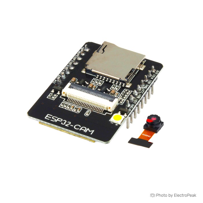
The ESP32-CAM is a development board based on the ESP32-S microcontroller, featuring a camera module. It is designed for projects that require wireless communication and camera capabilities.
Creating an account has many benefits: check out faster, keep more than one address, track orders and more.

We offer free shipping on all orders over $35 and under 2kg.
Please note that free shipping is only available for orders under 2kg.
DHL is a renowned shipping courier known for its global reach and reliable delivery services. With a vast network and advanced logistics capabilities, DHL offers fast and secure shipping solutions for international shipments.
For the majority of countries, DHL provides an estimated delivery time of 5 to 7 days.
In certain instances, DHL may not be available for shipments to EU countries. In such cases, we may opt to ship your order using FedEx instead of DHL. Rest assured, FedEx offers a comparable estimated time of arrival (ETA) and your package should typically arrive within 5-7 days.
The base shipping cost for DHL is $35. You can see the final shipping amount on the checkout page. If your order is over $200 and less than 2kg, you will qualify for free shipping through DHL Express.
Yun Express is a shipping courier known for its reliable and efficient international shipping services. With a strong global network and advanced logistics solutions, Yun Express ensures timely delivery and provides tracking options for customers to monitor their shipments.
The delivery time in most cases is 10-15 business days. If your order is over $35 and less than 2kg,you will qualify for free shipping through YunExpress.
YunExpress shipments can be tracked here: https://www.yuntrack.com/
Our shipping term is FOB Shenzhen, which does not cover any customs fees. It is important to note that you may be responsible for paying any charges imposed by your country's government, such as duties, taxes, and additional fees imposed by the courier company.
 ESP32 WROOM-32D CP2102 WiFi Bluetooth Development Board Previous
In the world of microcontrollers, the ESP32-CAM stands out as a versatile and compact development board that integrates both Wi-Fi/Bluetooth capabilities and a camera module. Developed by Espressif Systems, the ESP32-CAM is designed for projects that require image and video processing, making it a popular choice among hobbyists, makers, and IoT enthusiasts. In this review, we'll delve into the key features, performance, and potential use cases of the ESP32-CAM, shedding light on why it has become a go-to solution for camera-enabled projects.


You can see the pinout of ESP32-CAM below.

The pinout of the ESP32-CAM development board typically includes a set of GPIO (General Purpose Input/Output) pins, power supply pins, camera-related pins, and other interface pins. Here's a basic pinout for the ESP32-CAM:
The pinout of the ESP32-CAM development board typically includes a set of GPIO (General Purpose Input/Output) pins, power supply pins, camera-related pins, and other interface pins. Here's a basic pinout for the ESP32-CAM:
Remember that some GPIO pins may have specific functions during boot or operation, and certain pins may be reserved for certain functionalities.
Programming the ESP32-CAM involves several steps, and you can use the Arduino IDE or PlatformIO for development. For an in-depth tutorial visit Installing the ESP32 Board in Arduino IDE. Here's a brief step-by-step guide using the Arduino IDE:
Step 1: Install Arduino IDE
Download and install the Arduino IDE from the official Arduino website.
Step 2: Install ESP32 Board Support
Step 3: Select ESP32 Board
Go to "Tools" > "Board" and select "ESP32 Wrover Module" as the board.
Step 4: Wiring
Ensure that the ESP32-CAM is connected properly. Here's a basic wiring setup:
Step 5: Put ESP32-CAM in Programming Mode
Step 6: Upload the Code

The ESP32-CAM is a versatile development board, and there are numerous exciting projects and applications you can undertake with it. Here are some ideas to get you started:
Create a smart surveillance system with motion detection. The ESP32-CAM can capture images or videos when motion is detected, and you can even set it up to send alerts or notifications.
In order to build a surveillance camera, you will need to a micro SD memory.
If you intend to build a portable and standalone device, it will definitely need a batteries and a charger module.
Build a DIY home automation system with the ESP32-CAM. Use it to monitor home security, control smart devices, or even integrate it into a larger home automation ecosystem.
Using Home Assistant OS on Raspberry Pi 4 mini PC, and €œESP-Home€ ADD-ON, you can monitor and automate your site. You can read this instruction to setup and configure your ESP32 devices.
Develop a real-time video streaming application. The ESP32-CAM can capture and stream live video over Wi-Fi, allowing you to monitor a location remotely.
Experiment with image recognition and machine learning. You can use the camera to capture images and then process them for object detection or facial recognition using suitable libraries.
Build a weather station that not only measures environmental conditions but also captures images to document weather changes.
In order to measure these parameters, you can use sensors such as BME680 , temperature, humidity and pressure sensor module.
The ESP32-CAM development board is a popular platform for developing projects involving camera functionalities using the ESP32 microcontroller. Here are some frequently asked questions (FAQs) about the ESP32-CAM development board:
The ESP32-CAM is a development board based on the ESP32-S microcontroller, featuring a camera module. It is designed for projects that require wireless communication and camera capabilities.
The ESP32-CAM features an ESP32-S chip, OV2640 camera module, microSD card slot, and Wi-Fi/Bluetooth connectivity. It has GPIO pins for additional peripherals and sensors.
Yes, you can use the ESP32-CAM with other development environments besides the Arduino IDE. The ESP32-CAM is compatible with the Espressif IoT Development Framework (ESP-IDF), which is the official development framework for the ESP32 series. The ESP-IDF provides more advanced features and lower-level control compared to the Arduino IDE.
Additional Resources:
Refer to the ESP-IDF documentation for detailed information on using the framework.
The ESP-IDF comes with examples, including camera examples, which can serve as a good starting point for ESP32-CAM development.
While the Arduino IDE is beginner-friendly and suitable for many projects, the ESP-IDF provides more control and flexibility for advanced users who want to harness the full capabilities of the ESP32-CAM. Choose the development environment that best suits your project requirements and familiarity with the toolchain.
The ESP32-CAM can be powered using an external 5/3.3 V source connected to the 5/3.3V and GND pins.
The OV2640 camera on the ESP32-CAM supports a maximum resolution of 1600x1200 pixels.
The ESP32-CAM has GPIO pins that can be used to connect external sensors and peripherals. Refer to the pinout diagram for specific pin functionalities.
Yes, the ESP32-CAM can be programmed to capture images and stream video over Wi-Fi. Several examples and libraries are available to facilitate video streaming.
Yes, there is official documentation for the ESP32-CAM, which is provided by Espressif Systems, the manufacturer of the ESP32 series. The documentation includes technical details, specifications, and information on how to use the ESP32-CAM for development.
You can find the official documentation on the Espressif website. Here are the key resources:
For beginners, reading this article would help a lot: €œESP32-CAM Video Streaming and Face Recognition with Arduino IDE€
The ESP32-CAM itself does not have built-in audio processing capabilities. It primarily focuses on image and video processing through its integrated camera module. However, it is possible to achieve streaming of images with sound in an ESP32-CAM-based project by combining it with external components.
Here's a general overview of how you might approach streaming images with sound using the ESP32-CAM:
It's important to note that streaming audio and video in real-time can be resource-intensive, and the performance might depend on the specific requirements of your project. Carefully manage the available resources on the ESP32 and consider external processing solutions if needed.
According to the product specifications, the ESP32-CAM should only support 4 GB SD cards.
The ESP32-S chip -that used in this dev board- has 32 GPIO pins in total, but because many of them are used internally for the camera and the PSRAM, the ESP32-CAM only has 10 GPIO pins available. These pins can be assigned a variety of peripheral duties, such as UART, SPI, ADC, and Touch, by programming the appropriate registers.
The official ESP32-CAM has a AMS1117 voltage regulator that creates the 3.3V for the ESP. The AMS1117 has an Absolute Maximum Input Voltage of 15V. It has a Dropout Voltage of 1.1-1.3V. So you should stay above 4.6V to be on the safe side.
The maximum frame rate of the ESP32-CAM (OV2640 camera module) depends on various factors, including the resolution of the images or video being captured, the level of compression applied, and the processing power available.
Here are some general guidelines for the maximum frame rates based on common resolutions:
It's important to note that achieving the maximum frame rate depends on factors such as the complexity of the scene being captured, the available processing power, and the chosen settings for compression and other parameters.
If real-time video streaming or high frame rates are critical for your application, consider optimizing your code, adjusting camera settings, and experimenting with different resolutions and compression options to find the right balance between image quality and frame rate.
helloxxxx

Please complete your information below to login.
Sign In
Create New Account