Introduction
Welcome to our step-by-step tutorial on ESP32CAM! Are you curious about the exciting world of the Internet of Things (IoT) and eager to level up your video skills? In this comprehensive tutorial, we’ll get to know the ESP32CAM module. Whether you’re a tech enthusiast, a student, or a developer with a passion for IoT, this tutorial will equip you with the knowledge and skills needed to bring your related projects to life.
We’ll walk you through every step, from interfacing the ESP32CAM module to configuring the camera, capturing video frames, and streaming them wirelessly.
What You Will Learn
- Receiving images from ESP32CAM
- Face recognition with ESP32CAM
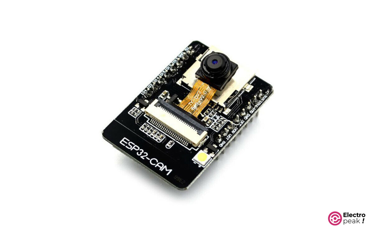
ESP32CAM in a Nutshell
ESP32CAM is a powerful development board that combines the ESP32 microcontroller with a camera module. It’s ideal for IoT projects that involve video streaming.
With built-in Wi-Fi and Bluetooth capabilities, the ESP32CAM module is perfect for remote monitoring, security systems, and any task that requires live, wireless video streaming.
ESP32CAM Features
- The tiniest SoC module (Wi-Fi & Bluetooth)
- A Low-power 32-bit CPU
- The maximum clock frequency of 160MHz, and 600 DMIPS of computing power
- Internal 520KB SRAM, plus an external MPSRAM4
- Supporting UART/SPI/I2C/PWM/ADC/DAC
- Compatibility with cameras like OV2640 and OV7670
- An onboard flash lamp
- Image uploading via WiFi
- TF card support
- Multiple sleep modes
- LwIP and FreeRTOS
- STA/AP/STA+AP operating modes
- Smart Config/AirKiss technology support
ESP32CAM Applications
ESP32CAM opens up a whole new world of possibilities with its advanced features and customization options for video streaming. Let’s explore a few exciting applications:
• Security purposes: With several ESP32CAM modules, you can build a smart security system.
• Robotics: By sending images over Wi-Fi and processing them with some powerful hardware, ESP32CAM becomes a key player in all sorts of robotics projects.
• IoT: When it comes to executing IoT projects, visuals play a vital role. ESP32CAM offers many features—a microcontroller, built-in Wi-Fi, Bluetooth, and a camera—so it’s perfect for smart facilities.
• Applications Combined with image processing software (like OpenCV): Using ESP32CAM, you can add image processing to your projects.
ESP32CAM Pinout
This module has 16 pins:
5V: Power supply
GND: Ground
GPIO2-16: Digital input and output pins. They also come with a bunch of extra features like:
- Analog-to-digital conversion (7 channels)
- SPI communication
- Memory card port
- UART
Here’s the pinout in the image below:
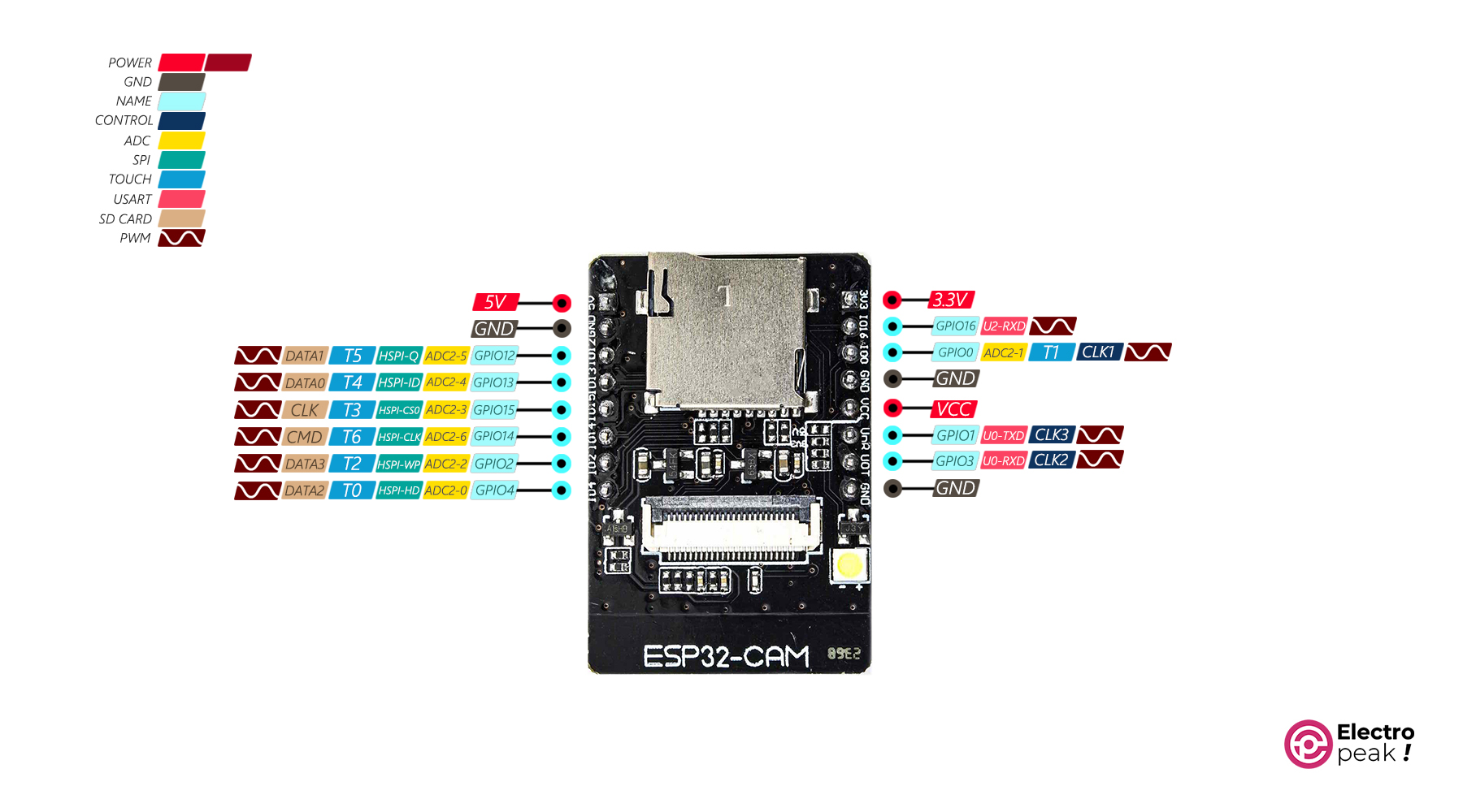
Using the EPS32CAM module, you have to remember that the pins with the yellow tag are for connecting a memory card. If you’re using a memory card, the other functions of these pins won’t be active.
Required Materials
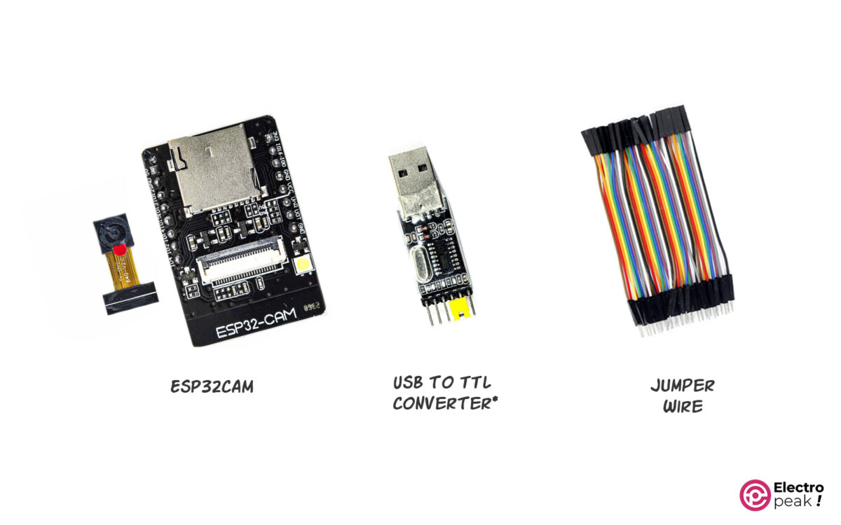
*: You can use any USB to serial converter that can handle 3.3 volts.
Setting Up a Video Streaming Server with ESP32CAM
Step1: Wiring
The ESP32CAM module doesn’t have a USB port, so you can’t just plug it directly into your computer. No worries, though! To program and communicate with the serial port of the module, you’ll need a USB to TTL converter. Check out the image below to see how to wire it up.
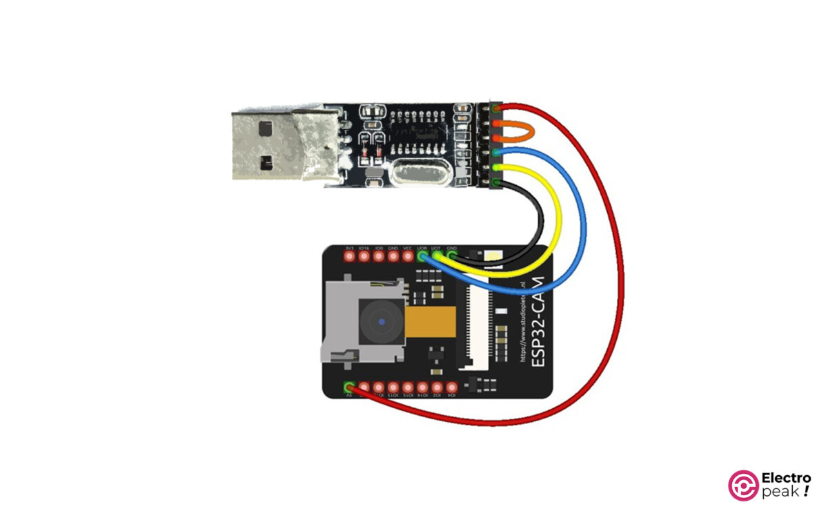
The USB to TTL converter contains the following pins (from right to left):
+5V, VCC, +3.3V, TX, RX, and GND
Step 2: Video Streaming Code with ESP32-CAM
In this tutorial, we will use an example already available in the ESP32 library. So, follow these steps:
1. Install the ESP32 Add-on: You can visit this link if you need any help.
2. Open up the example called “CameraWebServer.ino” found at Files -> Examples -> ESP32 -> Camera.
Now, Let’s Get to the Code
When you open that example, the code below will appear. But before you can run it, you have to make a couple of small changes. We’ll explain them later on.
#include "esp_camera.h"
#include <WiFi.h>

//
// WARNING!!! PSRAM IC required for UXGA resolution and high JPEG quality
// Ensure ESP32 Wrover Module or other board with PSRAM is selected
// Partial images will be transmitted if image exceeds buffer size
//
// You must select a partition scheme from the board menu that has at least 3MB of APP space.
// Face Recognition is DISABLED for ESP32 and ESP32-S2, because it takes up from 15
// seconds to process a single frame. Face Detection is ENABLED if PSRAM is enabled as well

// ===================
// Select camera model
// ===================
//#define CAMERA_MODEL_WROVER_KIT // Has PSRAM
//#define CAMERA_MODEL_ESP_EYE // Has PSRAM
//#define CAMERA_MODEL_ESP32S3_EYE // Has PSRAM
//#define CAMERA_MODEL_M5STACK_PSRAM // Has PSRAM
//#define CAMERA_MODEL_M5STACK_V2_PSRAM // M5Camera version B Has PSRAM
//#define CAMERA_MODEL_M5STACK_WIDE // Has PSRAM
//#define CAMERA_MODEL_M5STACK_ESP32CAM // No PSRAM
//#define CAMERA_MODEL_M5STACK_UNITCAM // No PSRAM
#define CAMERA_MODEL_AI_THINKER // Has PSRAM
//#define CAMERA_MODEL_TTGO_T_JOURNAL // No PSRAM
//#define CAMERA_MODEL_XIAO_ESP32S3 // Has PSRAM
// ** Espressif Internal Boards **
//#define CAMERA_MODEL_ESP32_CAM_BOARD
//#define CAMERA_MODEL_ESP32S2_CAM_BOARD
//#define CAMERA_MODEL_ESP32S3_CAM_LCD

#include "camera_pins.h"

// ===========================
// Enter your WiFi credentials
// ===========================
const char* ssid = "Caferobot-2G";
const char* password = "caferobot.ir";

void startCameraServer();
void setupLedFlash(int pin);

void setup() {
 Serial.begin(115200);
 Serial.setDebugOutput(true);
 Serial.println();

 camera_config_t config;
 config.ledc_channel = LEDC_CHANNEL_0;
 config.ledc_timer = LEDC_TIMER_0;
 config.pin_d0 = Y2_GPIO_NUM;
 config.pin_d1 = Y3_GPIO_NUM;
 config.pin_d2 = Y4_GPIO_NUM;
 config.pin_d3 = Y5_GPIO_NUM;
 config.pin_d4 = Y6_GPIO_NUM;
 config.pin_d5 = Y7_GPIO_NUM;
 config.pin_d6 = Y8_GPIO_NUM;
 config.pin_d7 = Y9_GPIO_NUM;
 config.pin_xclk = XCLK_GPIO_NUM;
 config.pin_pclk = PCLK_GPIO_NUM;
 config.pin_vsync = VSYNC_GPIO_NUM;
 config.pin_href = HREF_GPIO_NUM;
 config.pin_sscb_sda = SIOD_GPIO_NUM;
 config.pin_sscb_scl = SIOC_GPIO_NUM;
 config.pin_pwdn = PWDN_GPIO_NUM;
 config.pin_reset = RESET_GPIO_NUM;
 config.xclk_freq_hz = 20000000;
 config.frame_size = FRAMESIZE_UXGA;
 config.pixel_format = PIXFORMAT_JPEG; // for streaming
 //config.pixel_format = PIXFORMAT_RGB565; // for face detection/recognition
 config.grab_mode = CAMERA_GRAB_WHEN_EMPTY;
 config.fb_location = CAMERA_FB_IN_PSRAM;
 config.jpeg_quality = 12;
 config.fb_count = 1;

 // if PSRAM IC is present, init with UXGA resolution and higher JPEG quality
 // for larger pre-allocated frame buffer.
 if(config.pixel_format == PIXFORMAT_JPEG){
 if(psramFound()){
 config.jpeg_quality = 10;
 config.fb_count = 2;
 config.grab_mode = CAMERA_GRAB_LATEST;
 } else {
 // Limit the frame size when PSRAM is not available
 config.frame_size = FRAMESIZE_SVGA;
 config.fb_location = CAMERA_FB_IN_DRAM;
 }
 } else {
 // Best option for face detection/recognition
 config.frame_size = FRAMESIZE_240X240;
#if CONFIG_IDF_TARGET_ESP32S3
 config.fb_count = 2;
#endif
 }

#if defined(CAMERA_MODEL_ESP_EYE)
 pinMode(13, INPUT_PULLUP);
 pinMode(14, INPUT_PULLUP);
#endif

 // camera init
 esp_err_t err = esp_camera_init(&config);
 if (err != ESP_OK) {
 Serial.printf("Camera init failed with error 0x%x", err);
 return;
 }

 sensor_t * s = esp_camera_sensor_get();
 // initial sensors are flipped vertically and colors are a bit saturated
 if (s->id.PID == OV3660_PID) {
 s->set_vflip(s, 1); // flip it back
 s->set_brightness(s, 1); // up the brightness just a bit
 s->set_saturation(s, -2); // lower the saturation
 }
 // drop down frame size for higher initial frame rate
 if(config.pixel_format == PIXFORMAT_JPEG){
 s->set_framesize(s, FRAMESIZE_QVGA);
 }

#if defined(CAMERA_MODEL_M5STACK_WIDE) || defined(CAMERA_MODEL_M5STACK_ESP32CAM)
 s->set_vflip(s, 1);
 s->set_hmirror(s, 1);
#endif

#if defined(CAMERA_MODEL_ESP32S3_EYE)
 s->set_vflip(s, 1);
#endif

// Setup LED FLash if LED pin is defined in camera_pins.h
#if defined(LED_GPIO_NUM)
 setupLedFlash(LED_GPIO_NUM);
#endif

 WiFi.begin(ssid, password);
 WiFi.setSleep(false);

 while (WiFi.status() != WL_CONNECTED) {
 delay(500);
 Serial.print(".");
 }
 Serial.println("");
 Serial.println("WiFi connected");

 startCameraServer();

 Serial.print("Camera Ready! Use 'http://");
 Serial.print(WiFi.localIP());
 Serial.println("' to connect");
}

void loop() {
 // Do nothing. Everything is done in another task by the web server
 delay(10000);
}
Code Explanation
1. Loading up the required libraries.
#include "esp_camera.h"
#include <WiFi.h>
2. Selecting the camera model:
At lines 16 to 30, select the camera model you’re working with and uncomment it. The camera installed on our ESP32CAM module is an AI_THINKER model.
#define CAMERA_MODEL_AI_THINKER // Has PSRAM
3. Loading up the “camera_pins.h” library: the one that tells us how to connect those camera pins to the ESP32.
#include "camera_pins.h"
4. Configuring your Wi-Fi network: Enter the name (SSID) and password of your Wi-Fi network.
const char* ssid = "**************";
const char* password = "**************";
5. Defining the functions to set up the server, web page and camera flash.
void startCameraServer();
void setupLedFlash(int pin);
6. Last but not least, we have the “setup()” function:
- Setting up the serial communication and activating the debug messages.
Serial.begin(115200);
  Serial.setDebugOutput(true);
- Configuring the camera pins on ESP32 according to the “camera_pins.h” file.
camera_config_t config;
  config.ledc_channel = LEDC_CHANNEL_0;
  config.ledc_timer = LEDC_TIMER_0;
  config.pin_d0 = Y2_GPIO_NUM;
  config.pin_d1 = Y3_GPIO_NUM;
  config.pin_d2 = Y4_GPIO_NUM;
  config.pin_d3 = Y5_GPIO_NUM;
  config.pin_d4 = Y6_GPIO_NUM;
  config.pin_d5 = Y7_GPIO_NUM;
  config.pin_d6 = Y8_GPIO_NUM;
  config.pin_d7 = Y9_GPIO_NUM;
  config.pin_xclk = XCLK_GPIO_NUM;
  config.pin_pclk = PCLK_GPIO_NUM;
  config.pin_vsync = VSYNC_GPIO_NUM;
  config.pin_href = HREF_GPIO_NUM;
  config.pin_sscb_sda = SIOD_GPIO_NUM;
  config.pin_sscb_scl = SIOC_GPIO_NUM;
  config.pin_pwdn = PWDN_GPIO_NUM;
  config.pin_reset = RESET_GPIO_NUM;
- Configuring the camera and image parameters.
config.xclk_freq_hz = 20000000;
  config.frame_size = FRAMESIZE_UXGA;
  config.pixel_format = PIXFORMAT_JPEG; // for streaming
  //config.pixel_format = PIXFORMAT_RGB565; // for face detection/recognition
  config.grab_mode = CAMERA_GRAB_WHEN_EMPTY;
  config.fb_location = CAMERA_FB_IN_PSRAM;
  config.jpeg_quality = 12;
  config.fb_count = 1;
- Camera Activation
  esp_err_t err = esp_camera_init(&config);
  if (err != ESP_OK) {
    Serial.printf("Camera init failed with error 0x%x", err);
    return;
  }
- WiFi Connection
  WiFi.begin(ssid, password);
  WiFi.setSleep(false);
• Server Activation
startCameraServer();
- Finally, if everything goes smoothly, we print the ESP32CAM module’s IP address to the serial port.
  Serial.print("Camera Ready! Use 'http://");
  Serial.print(WiFi.localIP());
  Serial.println("' to connect");
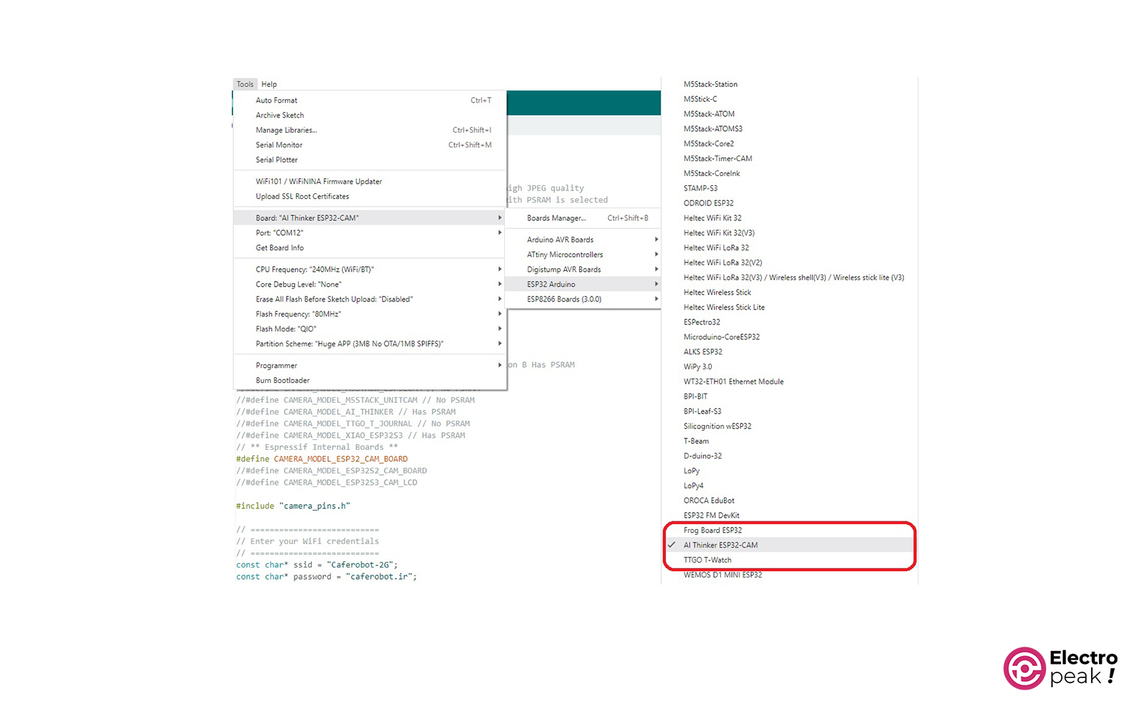
Programming ESP32CAM
First, set the ESP32CAM board type to “AIThinker ESP32-CAM.”
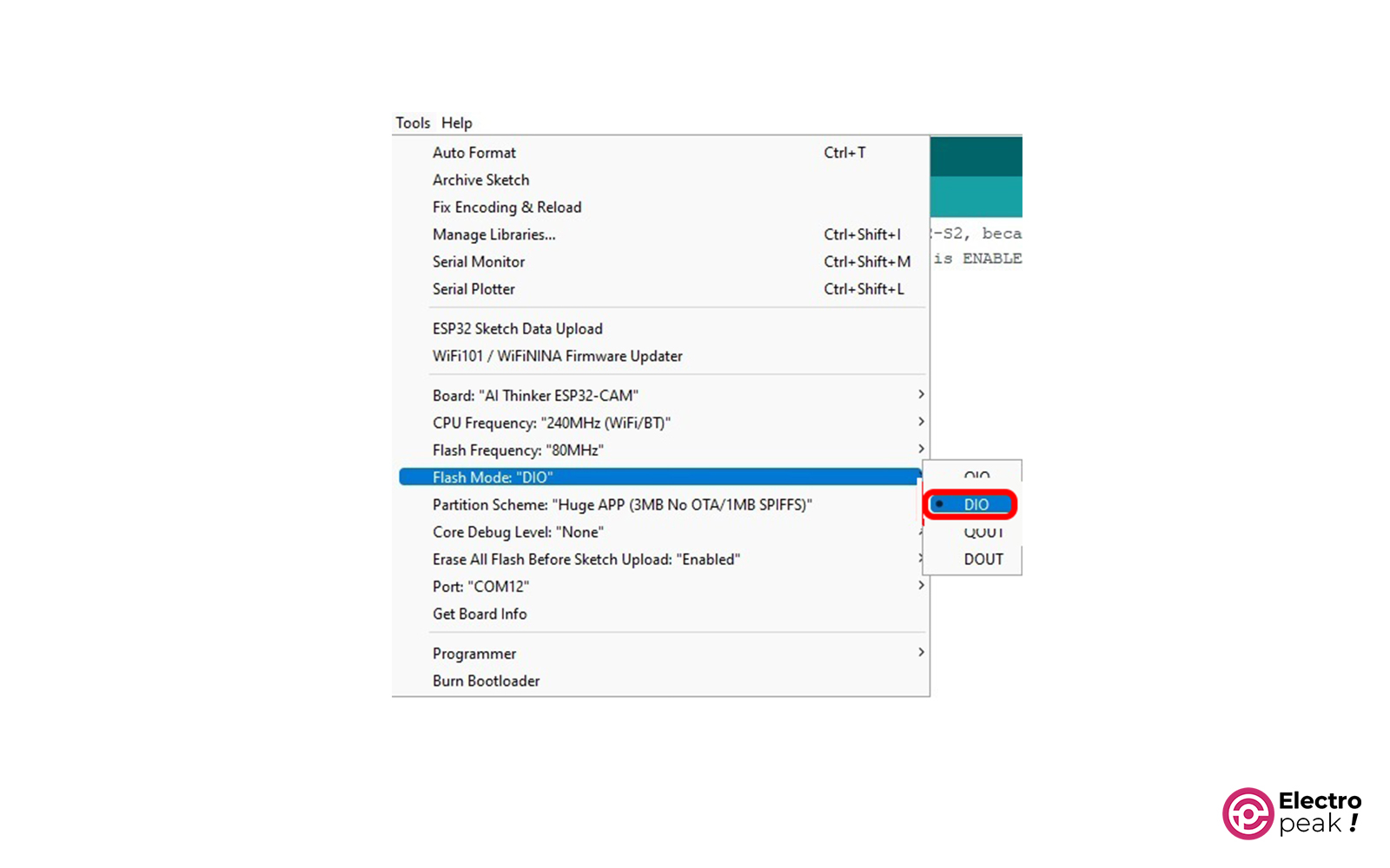
Next, set the “Flash Mode” to “DIO.”
Select the “Huge APP” option for the “Partition Scheme.”
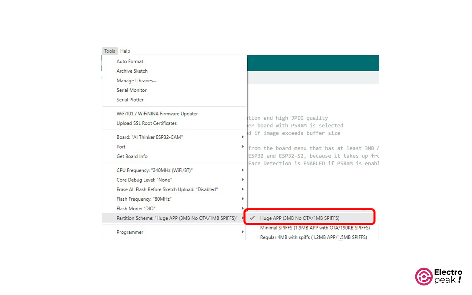
Finally, select the serial port and click the program button.
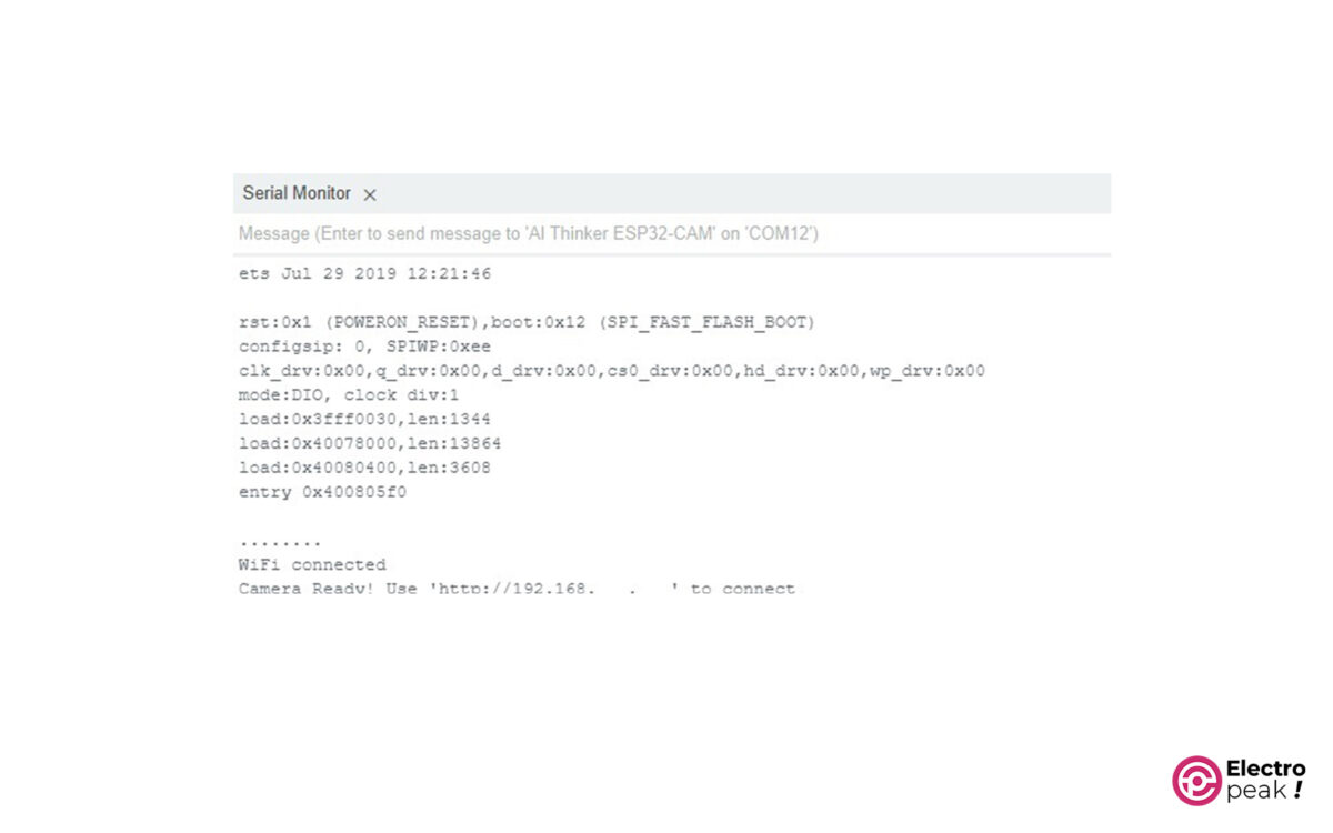
If everything goes as planned, the IP address of the ESP32CAM module will be printed in the serial window.
Now, open this address in your browser. You’ll see the window below.
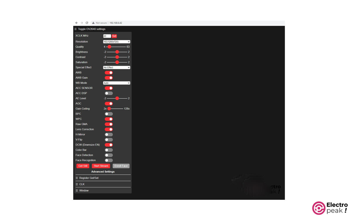
If you click on the “Start stream” button, the image received from the ESP32Cam module will be displayed on the screen.
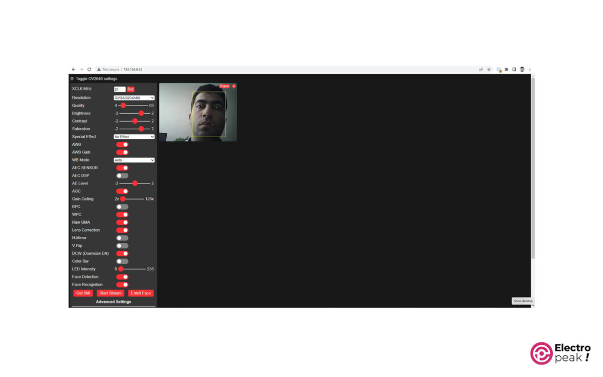
Face Recognition with ESP32CAM
To enable face recognition, first set the image resolution to QVGA and then activate the “Face Detection” and “Face Recognition” options.
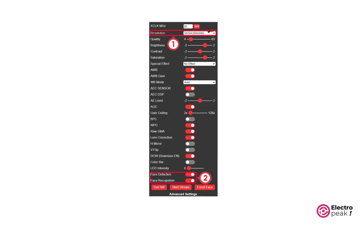
Now you will see an image like the one below. The ESP32CAM module has recognized the face.
Troubleshooting the ESP32CAM Video Streaming
1- Can't Program the ESP32CAM Board
To fix this issue, let’s go through a quick checklist:
- Double-check your wiring.
- f your USB-to-TTL converter can switch between 5V and 3.3V, make sure it’s set to 3.3V.
- Measure the output voltage of the converter with a voltmeter. It shouldn’t be less than 5V.
- Pay attention to selecting the right board and camera.
- Before each programming attempt, don’t forget to connect the IO0 pin to GND and press the RST button.
2- This Message: “Brownout detector was triggered"
If you keep seeing this message pop up in the serial monitor, try these:
- Use a shorter USB cable (with data wires).
- Connect to a different USB port on your computer or use a powered USB hub.
3- This Error: "Sketch too big"
If you face this error, chances are you forgot to set the “Partition Scheme” to “Big APP.” Fix that up and try programming again.
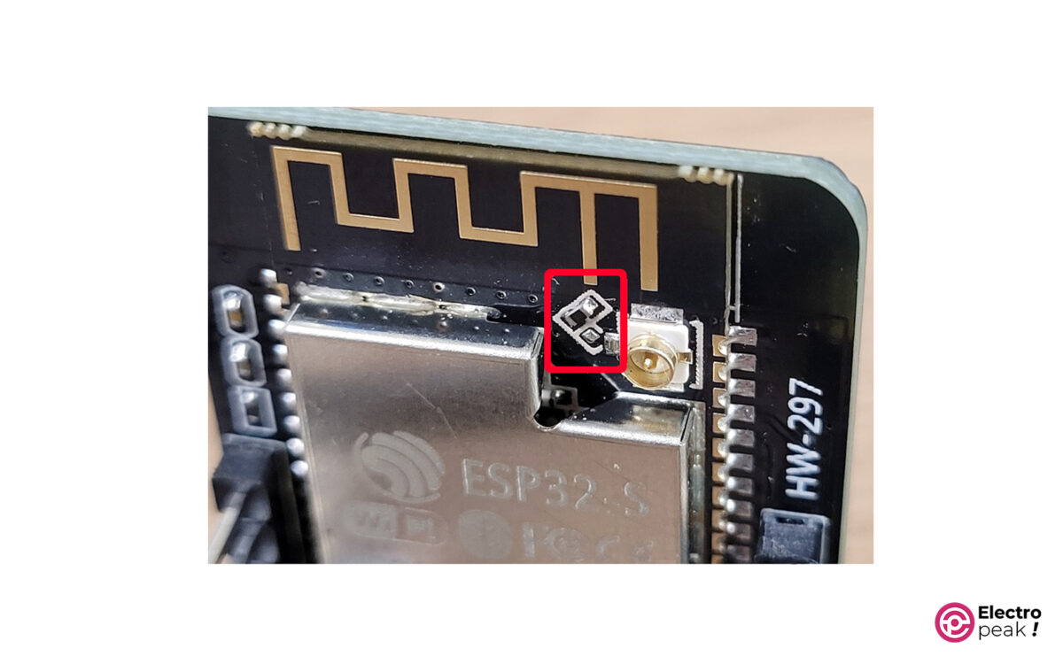
4- Weak Signal of WiFi Antenna
If you’re struggling to connect to the Wi-Fi network because of the distance to the router, get yourself an external antenna. Just remember to remove the 0-ohm resistor next to the antenna port of the ESP32CAM module.
To use the external antenna, just remove the marked resistor in the image below and solder it vertically.
5- Can't Access the Web Server Page
If the ESP32CAM prints the IP address in the serial monitor, but you can’t open it in your browser, you might be trying to connect to the web server with multiple tabs. Remember, only one client can connect to the ESP32CAM web server.
6- Image Delay
If you’re experiencing a delay in image updates:
- Provide a separate 5V power supply for the ESP32CAM module.
- Reduce the image resolution.
- Use an external antenna.
What’s Next?
In this tutorial, you’ve gotten familiar with the ESP32CAM module. We used the code in the ESP32 library to upload the camera images to a web server. And we learned how to configure some of the parameters on the web page.
Now, with the ESP32CAM module, you can dive into exciting projects like:
- Security Robot: A mobile robot that patrols around an area and captures and transmits images of the surroundings.
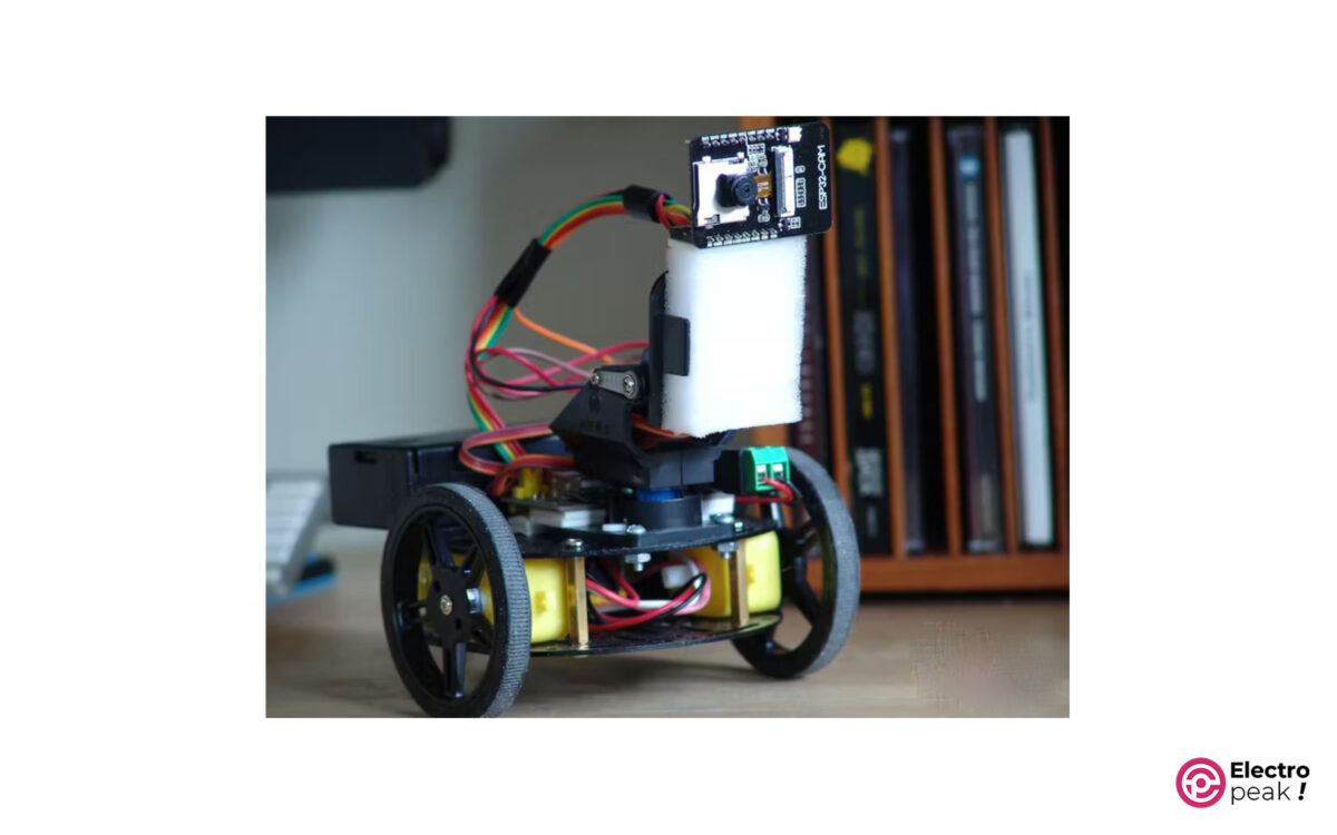
Get more details about this project right here.
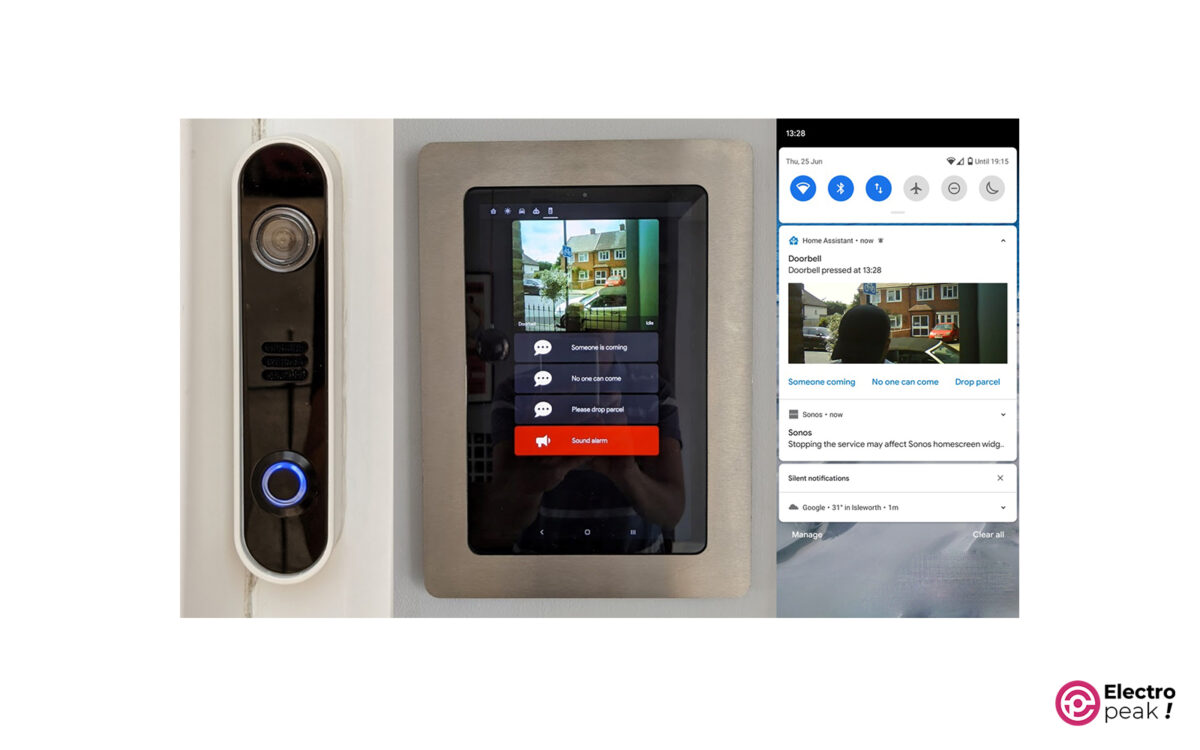
- Smart Video Doorbell: When someone rings your doorbell, you’ll see their face on your cell phone, and can remotely control the door.