
Product added to cart

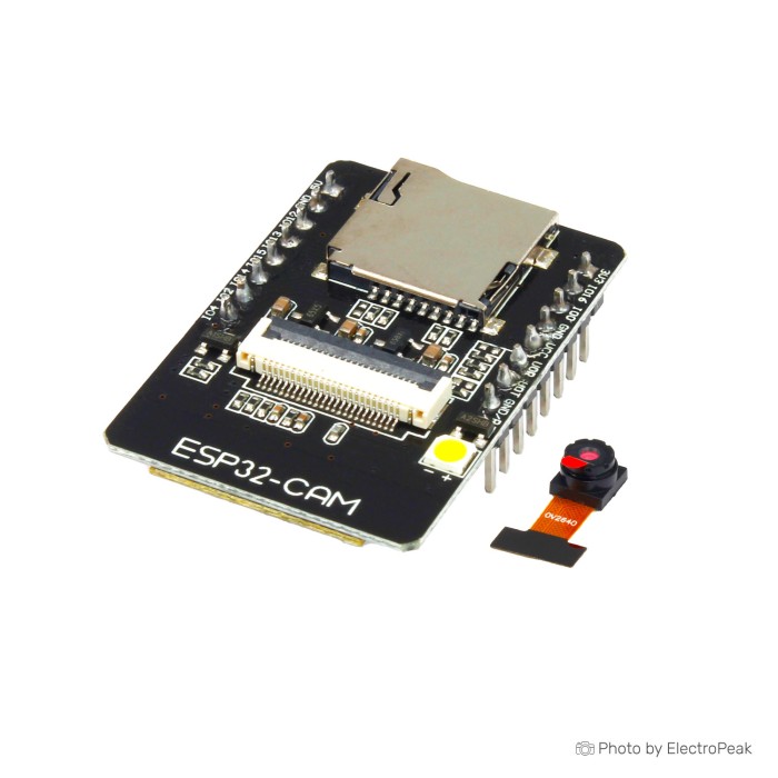
ESP32-CAM WiFi Bluetooth Camera Development Board
SAVE
As low as $6.9500
In stock
Only %1 left
SKU
COM-03-047
Ships in 2-3 business days, then:
Free delivery in 12-15 days by Tracked Economic Shipping on orders over $100.
Free delivery in 7-10 days by Express Shipping on orders over $300.
More shipping info

Shop with confidence Learn More
 ESP32 WROOM-32D CP2102 WiFi Bluetooth Development Board Previous
ESP32-CAM WiFi Bluetooth Camera Development Board review
This board is a compact ESP32 board built in the familiar ESP32-CAM format, with Wi‑Fi, Bluetooth, an OV2640 camera, and a microSD slot on a small 40x27mm PCB. It fits makers building still-image capture, simple web streaming, or sensor-triggered camera nodes, rather than buyers expecting a polished finished camera product.
The main trade-off is setup convenience. There is no USB port on the bare module, and the practical GPIO headroom is much tighter than many buyers expect once the camera, storage, boot pins, and serial programming pins are accounted for.
Specifications of ESP32-CAM WiFi Bluetooth Camera Development Board
- Microcontroller: ESP32 dual-core microcontroller (Tensilica LX6) operating at 240MHz.
- Wi-Fi and Bluetooth: Integrated Wi-Fi (802.11 b/g/n) and Bluetooth (4.2 BR/EDR and BLE) capabilities.
- Camera Module: OV2640 camera module with resolution up to resolutions up to 1600x1200 pixels.
- Storage: 520 KB SRAM, 2~8MB External PSRAM Flash Memory & MicroSD card slot for external storage.
- GPIO Pins: 10 General Purpose Input/Output pins for connecting external sensors, peripherals, and displays.
- Programming Interface: Can be programmed using the Arduino IDE or Espressif IoT Development Framework (ESP-IDF) through USB-TTL converter.
- USB Connectivity: without USB port.
- Power Supply: Can be powered through external 5V source (If have a DC power source nearside, you can use DC/DC converter modules)
- Dimensions: 40x27mm.
- Buttons: Reset button for resetting the board.
- Voltage Regulator: Integrated 3.3v voltage regulator for stable operation.
- Antenna: Integrated antenna for Wi-Fi and Bluetooth communication. It is possible to connect an external 2.4GHz antenna.
ESP32-CAM specifications and hardware limits
At the core is a dual-core ESP32 running at up to 240MHz, with built-in 2.4 GHz Wi‑Fi and Bluetooth 4.2. That combination keeps this board useful for untethered image nodes: it can capture, store, and serve images over the network without a separate radio module.
The OV2640 camera tops out at 1600x1200 pixels. That is enough for snapshots, basic monitoring, QR or simple vision experiments, and the large body of existing ESP32-CAM examples that expect the OV2640 sensor. If software example compatibility is your main concern, this sensor choice helps.
The microSD slot matters more than it first appears. It lets the board log images locally when Wi‑Fi is intermittent, buffer data for later upload, or work as a simple standalone image recorder instead of a streaming-only device.
The small 40x27mm footprint helps in enclosure builds, trail-camera prototypes, and compact home automation nodes. You get camera, wireless, storage, reset, and power regulation on one board. That same density is why the I/O situation is restrictive.
The listed memory line needs careful reading. The board provides 520 KB SRAM and the specification line states “2~8MB External PSRAM Flash Memory,” but that wording combines PSRAM and flash into one phrase. For this version, the exact flash capacity and exact PSRAM capacity are not clearly pinned down, so if your firmware design depends on a guaranteed memory size, confirm that before purchase.
Antenna support also deserves a realistic expectation. The board includes an integrated antenna, which is the standard path for most builds. External 2.4GHz antenna support is described for the product family, but whether the required connector and switching hardware are present on this exact board depends on the shipped revision.
The headline GPIO count is 10, but that does not mean 10 unrestricted pins. This format uses many signals internally or conditionally: camera data lines, microSD signals, serial upload pins, boot-strapping pins, PSRAM-related use on some revisions, and the flash LED function all reduce how much clean, conflict-free I/O is left for your own sensors or displays.
If you need more memory headroom, a newer platform, or substantially more free I/O, the ESP32-S3 CAM is the better fit.
Compatibility summary
| Area | What to expect |
|---|---|
| Development environments | Arduino IDE and ESP-IDF are supported. |
| Programming connection | Programming is done through an external USB-to-TTL adapter on U0R/U0T, or by using an ESP32-CAM-MB style programmer shield. |
| USB | There is no USB port on the bare board. |
| Logic family | This is an ESP32-family board in a 3.3V logic context. Do not treat the GPIOs as 5V-tolerant. |
| Power input | The board is intended to run from an external 5V source. A stable 5V supply path is the safest choice for camera and Wi-Fi loads. |
| Wireless | 2.4 GHz Wi-Fi 802.11 b/g/n and Bluetooth 4.2 BR/EDR and BLE are built in. |
| Camera software assumptions | Use examples and board definitions that match the ESP32-CAM / AI-Thinker-style pin map. Code written for other ESP32 camera boards may use different GPIO assignments. |
| Storage | A microSD card slot is present. The exact tested maximum capacity for this board is not confirmed. |
| Audio | There is no built-in audio. Sound projects need external hardware. |
| Antenna | An integrated antenna is standard. External antenna support is not confirmed for every revision. |
| GPIO availability | Limited in practice because camera, PSRAM, microSD, boot strapping, UART, and LEDs share pins. |
| Best fit environments | Indoor prototyping, embedded hobby projects, and custom enclosed builds. |
| Poor fit environments | Unprotected outdoor deployment, safety-critical systems, and ready-made security-camera expectations. |
ESP32-CAM programming and first power-up
The first thing to know before ordering is simple: this board does not plug into a computer by itself. The bare module has no USB port, so you need either an ESP32-Cam-MB USB to TTL Programmer Shield or a separate CH340G USB to TTL Converter to upload code and read serial output.
Once that hardware is in place, programming support is straightforward. Arduino IDE works well for common examples and quick testing, while ESP-IDF is available when you want lower-level control. Board-package menus and naming can change over time, so follow current setup guidance instead of relying on one old fixed board selection rule.
For manual wiring, connect power, cross TX and RX correctly, and make sure ground is shared. In other words, the adapter TX should go to the board receive pin, and the adapter RX should go to the board transmit pin. A small Breadboard Jumper Wire Kit - 140 Pieces is enough for the initial setup.
To enter programming mode, pull GPIO0 low, then reset the board and upload your code. After flashing, remove the GPIO0-to-GND strap and reset again for normal boot. Leaving GPIO0 grounded after upload is one of the most common reasons a board appears dead even though the flash succeeded.
Power quality matters more here than on a plain ESP32 dev board without a camera. Weak USB-to-TTL adapters, thin jumper wires, and unstable 5V rails can all lead to brownouts, failed camera initialization, or erratic boot behavior, especially when Wi‑Fi and the camera start together.
If easier USB programming and a battery-oriented design matter more than staying with this bare-board format, M5CAM with OV2640 is the same general class of board sold in a more integrated form.
Quick start
- Connect the board to an ESP32-CAM-MB programmer shield or a USB-to-TTL adapter.
- Wire power and serial correctly, with TX and RX crossed and a shared ground.
- Pull GPIO0 low for flashing, then reset the board.
- Install ESP32 board support in Arduino IDE or use ESP-IDF.
- Upload a known ESP32-CAM example that matches the board’s camera pin configuration.
- Remove the GPIO0-to-GND programming strap and reset for normal boot.
- Confirm the board boots and the camera initializes without brownout or sensor errors.
For software, use Arduino IDE with the ESP32 board package or ESP-IDF. Your USB-to-TTL adapter may also need its own driver. This guide for installing the ESP32 board in Arduino IDE is the shortest path if you are starting from a clean system.
A good first test is a basic camera example or web-camera example that matches the ESP32-CAM pin definition. The expected result is a successful upload, a normal boot after removing the GPIO0 programming strap, and either a reachable camera page or a clean camera initialization message on serial output.
- Common first-time mistakes: buying the board without a programmer
- Common first-time mistakes: TX/RX not crossed
- Common first-time mistakes: no common ground
- Common first-time mistakes: leaving GPIO0 tied low after flashing
- Common first-time mistakes: weak power causing brownouts or camera init failure
- Common first-time mistakes: selecting code or board settings meant for a different ESP32 camera board
ESP32-CAM pinout, GPIO limits, and shared pins
This is the section that prevents the most wrong purchases. The stated 10 GPIO pins do not mean 10 freely usable pins in the same sense as a regular ESP32 dev board with USB and a large header set. On this layout, several exposed pins are shared with camera signals, microSD functions, boot behavior, serial programming, PSRAM-related use, or onboard LED behavior.
GPIO0 is the first important constraint because it controls boot mode. Pull it low to flash firmware; leave it in normal state for everyday boot. That makes it a poor choice for an external signal that could accidentally change state during reset.
GPIO1 and GPIO3 are the main UART pins used during programming and serial debugging. You can repurpose them later in some builds, but if your workflow depends on easy serial logs and repeated reflashing, they are not really “free” pins.
GPIO4 is a classic source of confusion on ESP32-CAM boards. It is commonly tied into the flash LED function and microSD-related behavior, so using it for another peripheral while also expecting clean LED or storage behavior can create hard-to-diagnose side effects.
GPIO16 and GPIO17 also deserve caution. On boards where PSRAM is active, those signals may not behave like spare GPIOs you can allocate casually, especially in camera-heavy firmware.
The practical result is that sensor add-ons are possible, but pin planning has to come first. A PIR input, limit switch, or one carefully chosen environmental sensor is realistic. A project that expects several sensors, a display, audio hardware, and clean SD logging on the same board quickly runs into conflicts.
Board-specific camera pin maps matter too. Many ESP32 camera tutorials assume an AI-Thinker-style layout, while other ESP32 camera boards use different assignments. If code was written for another camera board, it may compile but still fail at camera init because the pin map does not match this hardware.
If your design really needs substantially more free I/O, ESP32-S3 CAM is a more suitable branch of the same product family.
ESP32-CAM weaknesses and buyer mistakes
The biggest weakness is convenience. No built-in USB means extra hardware, extra wiring, and a more manual upload process from day one. For experienced users that is manageable; for first-time buyers it is the main source of avoidable frustration.
Power sensitivity is the next issue. Camera startup, Wi‑Fi activity, and the flash LED can push weak power setups into brownout resets or camera-init errors. Shorter wiring, a solid 5V source, and realistic current headroom make a noticeable difference.
Another limitation is board variation. ESP32-CAM modules from different OEM sources can differ in regulator choice, USB support on companion boards, PSRAM presence or size, antenna implementation, reset behavior, and sometimes even the exact camera subassembly. That does not make them unusable, but it does mean one tutorial’s assumptions do not always transfer cleanly.
Audio is not part of the base design. There is no built-in microphone or onboard audio processing path, so an audio/video intercom or synchronized A/V stream requires external hardware and extra integration work.
Processing headroom is also limited for advanced vision work. Existing demos such as simple face-recognition examples can be useful for learning, but this board is not the right choice when the job demands heavier real-time vision, polished continuous video, or predictable long-run streaming behavior.
It is also worth treating this as a maker platform, not a secure surveillance appliance. If the target is a finished security camera with hardened software, reliable long-term storage, remote management, enclosure design, and network security controls, that work still has to be done around the board.
Common setup mistakes come up repeatedly:
- Assuming the board has a built-in USB port for programming
- Buying it without a USB-to-TTL adapter or ESP32-CAM-MB programmer
- Wiring USB-to-TTL TX to TX and RX to RX instead of crossing them
- Leaving GPIO0 connected to GND after uploading
- Treating all exposed pins as freely available GPIOs
- Using GPIO4 for an external function while also expecting clean flash LED or microSD behavior
- Using GPIO16/17 as if they are always free while PSRAM/camera functions are active
- Powering from an inadequate or unstable source and then chasing camera-init or brownout errors
- Assuming all ESP32 camera-board tutorials use the same pin map
- Expecting integrated audio or an out-of-box audio/video camera
- Assuming the board is a ready-made secure surveillance product rather than a maker platform
- Assuming the 4 GB SD-card note applies universally to every software setup and board revision
If you need a newer camera platform with an onboard microphone and a more modern compact design, Seeed XIAO ESP32S3 Sense is the more natural fit.
ESP32 camera board alternatives: OV2640 vs OV3660 vs OV5640 vs ESP32-S3
This standard OV2640 version makes sense when you want broad example compatibility, a compact classic ESP32 camera format, and a board aimed at snapshots or simple streaming without moving to a newer platform. It is the familiar baseline that many community examples target.
| Board | When it makes sense | Main trade-off to know |
|---|---|---|
| This ESP32-CAM with OV2640 | Best when you want the common classic ESP32-CAM layout, broad example compatibility, microSD support, and compact basics. | No USB port on the bare board, limited practical GPIO, no built-in audio. |
| ESP32-CAM with OV3660 | A better fit if you specifically want its listed wide-angle and night-vision positioning, plus micro USB programming convenience. | Its trade-offs differ from this board because it is a different hardware package and setup path. |
| ESP32-CAM with OV5640 | Worth choosing when higher nominal image resolution is the main requirement and you want a USB-equipped option. | Resolution alone does not guarantee a better result for every workflow; it mainly helps when your project benefits from the 5MP sensor. |
| ESP32-CAM Plus with OV5640 | Useful when you want a slim board with USB Type-C and the OV5640 sensor, especially for tighter mechanical layouts. | It is a different physical format and has its own operating-range constraints. |
| ESP32-S3 CAM | The better fit when you need a newer ESP32-S3 platform, more memory headroom, or far more GPIO for larger integrations. | Camera sensor choice is optional in that family, so check the exact version you want. |
| Seeed XIAO ESP32S3 Sense | Strong choice for space-limited builds, onboard microphone needs, or a compact modern ESP32-S3 camera node. | For long-range communication, external U.FL antenna use matters in that design. |
No single one is the universal winner. If your priority is lower-friction USB setup, move to the USB-equipped variants. If your priority is newer ESP32-S3 features, more memory, microphone support, or more I/O, the S3 boards make more sense. If you mainly want the common OV2640 ecosystem and can handle manual flashing, this board still fits well.
ESP32-CAM project fit, accessories, and buying checklist
This board fits projects where the camera is one part of a custom embedded system rather than the whole product by itself. Good examples include Wi‑Fi snapshot nodes, motion-triggered image capture, simple MJPEG-style streaming experiments, microSD-backed image logging, and Home Assistant or MQTT image nodes. If you want a software starting point, this ESP32-CAM video streaming and face recognition guide is a useful reference.
It is a weaker fit for polished continuous security video, always-on battery streaming, or any project that expects integrated audio. Those jobs need more than this board offers on its own: cleaner power design, enclosure work, storage planning, network hardening, and in some cases a different camera platform entirely.
For category-level browsing or pairing with other wireless microcontroller builds, you can also explore the broader ESP32 range.
Accessories
Required
- ESP32-Cam-MB USB to TTL Programmer Shield — needed for first upload and ongoing debugging if you want a dedicated programming base.
- CH340G USB to TTL Converter — an alternative if you are wiring the board manually instead of using the dedicated shield.
- Breadboard Jumper Wire Kit - 140 Pieces — needed for connections between the board, programmer, and any external peripherals.
Recommended
- SanDisk Micro SD Memory Card - 32GB, 120MBps (class 10) — useful for local photo storage, image logging, and offline buffering.
- Stable 5V power source with current headroom — strongly recommended because weak supply paths are a common cause of brownouts and camera startup problems.
- Enclosure for deployment or outdoor protection — recommended if the board will be installed outside a bench setup.
Optional
- Sensor input for motion- or environment-triggered capture — useful for PIR, switch, or environmental trigger projects.
- External microphone or audio hardware for sound projects — required only if your design needs audio, because the board has no built-in audio support.
- External antenna only if the exact PCB revision supports it — worth considering for range-sensitive installations after revision confirmation.
- Battery/charger hardware for portable projects — useful for remote still-image builds with careful power management.
Purchase decision summary
Ideal for:
- Compact Wi‑Fi snapshot cameras
- Motion-triggered photo capture
- ESP32 camera learning projects
- microSD-backed image logging
- Basic streaming experiments where setup complexity is acceptable
Maybe for:
- Home Assistant or MQTT image nodes
- Battery-powered still-image projects with careful power design
- Light embedded vision demos using existing ESP32-CAM examples
Consider another option if:
- You want native USB programming
- You need many free GPIOs
- You need integrated audio
- You need stable high-quality continuous video
- You want a ready-made surveillance product rather than a maker board
Buying checklist
- ✓ Do you already have a USB-to-TTL adapter or an ESP32-CAM-MB programmer shield?
- ✓ Are you comfortable with manual flashing steps using GPIO0 and reset?
- ✓ Do you need only a few carefully chosen external I/O pins, not a GPIO-heavy build?
- ✓ Do you need local image storage, and if so, do you also need a microSD card?
- ✓ Is your power supply a stable 5V source with current headroom?
- ✓ Does your project require audio? If yes, this board needs extra hardware.
- ✓ Does your project require continuous polished security-camera behavior? If yes, this is likely the wrong tool.
- ✓ Do you need exact flash/PSRAM capacity confirmed before coding? If yes, ask before buying.
- ✓ Do you need guaranteed external antenna support? If yes, verify the shipped PCB revision first.
If you want integrated USB-TTL and a more battery-oriented camera board in the same general class, M5CAM with OV2640 is the more convenient version.
FAQ
Does this ESP32-CAM have a USB port for programming?
No. The bare module has no USB port, so programming is done through U0R/U0T with an external USB-to-TTL adapter or an ESP32-CAM-MB programmer shield.
How many GPIO pins can I really use on the ESP32-CAM?
Fewer than the headline number suggests. The board specifies 10 GPIO pins, but many are shared with the camera, microSD, boot functions, UART, flash LED behavior, or PSRAM-related functions.
Can I power the ESP32-CAM from 3.3V?
A stable 5V supply path is the safer choice. This board is specified for an external 5V source, and camera plus Wi‑Fi loads are a common reason weak power setups become unstable.
Is the OV2640 camera included?
The product is described with an OV2640 camera module, but the exact package contents are not fully clear here. If the camera module and ribbon are critical to your order, verify that before purchase.
Can it store photos locally?
Yes. The board has a microSD card slot for local storage, though the exact tested maximum card capacity for this version is not fully confirmed.
Can this board stream audio and video together?
Not by itself. There is no built-in audio processing capability, so audio requires external hardware and additional integration.
Why does the flash LED sometimes light during SD-card use?
Because GPIO4 is shared on the common ESP32-CAM layout. microSD-related activity on that shared pin can affect the flash LED.
Is this good for a security camera project?
It can work for DIY snapshots, motion-triggered image capture, and basic streaming experiments. It is not a finished secure surveillance product, so continuous polished security-camera behavior needs substantial extra engineering around the board.
What should I buy instead if I want easier setup?
For integrated USB-TTL convenience and battery-oriented camera development, M5CAM with OV2640 is the easier same-class choice. For newer ESP32-S3 features, more memory, or an onboard microphone, Seeed XIAO ESP32S3 Sense or ESP32-S3 CAM are the better direction.
| MCU/SoC | ESP32 |
|---|---|
| Product Family | ESP32 |
| Architecture | Tensilica Xtensa LX6 |
| CPU Cores | Dual-core |
| Clock Speed (MHz) | 240MHz |
| Flash | 2MB - 8MB |
| SRAM | 520KB |
| External Memory | External PSRAM |
| GPIO Pins | 10 Digital I/O pins |
| UART interface Pins | 1 |
| USB Ports | None |
| CAN Bus Support | Yes |
| Ethernet Support | No |
| Operating Voltage (V) | 3.3V |
| GPIO Voltage (V) | 3.3V |
| Wireless | Bluetooth, Wi-Fi |
| Form Factor | 40x27 mm |
| IDE Support | Arduino IDE, ESP-IDF |
| Input Voltage (V) | 5V |
| Antenna Type | Internal Antenna |
| Bluetooth Ver. | 4.2 |
Write Your Own Review

Please complete your information below to login.
Sign In
Create New Account