
Product added to cart

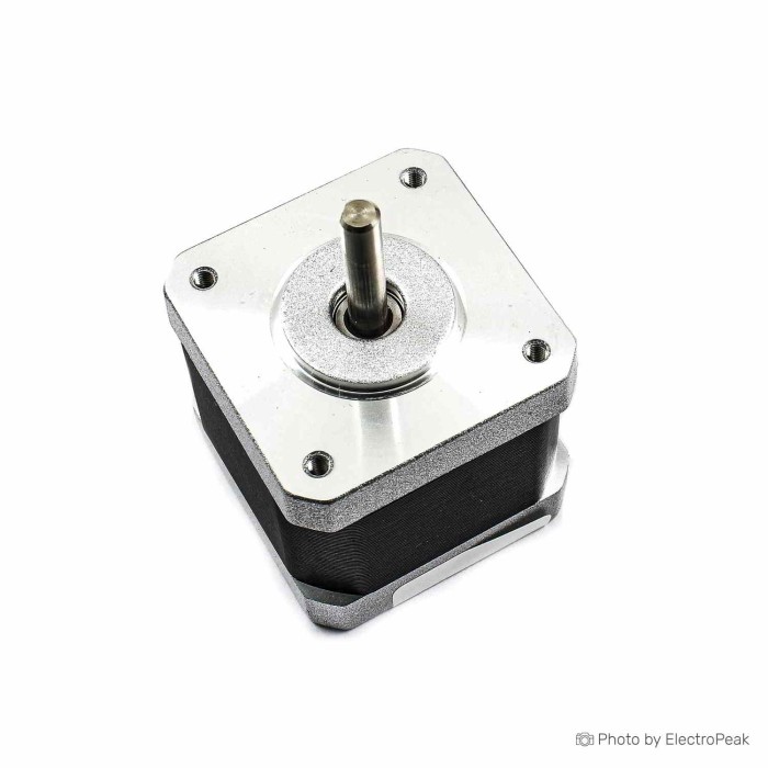
NEMA 17HS8401 1.7A Stepper Motor
$10.5000
In stock
SKU
MTR-05-013
Volume discounts:
- +25 5 % $9.9600
- +50 8 % $9.6900
- +100 10 % $9.4100
- +300 13 % $9.1400
- +500 16 % $8.8700
Product Variations:


Ships in 2-3 business days, then:
Free delivery in 12-15 days by Tracked Economic Shipping on orders over $100.
Free delivery in 7-10 days by Express Shipping on orders over $300.
More shipping info

Shop with confidence Learn More
 TMC2100 Stepper Motor Driver Previous
NEMA 17HS8401 Stepper Motor Specifications and Fit
The NEMA 17HS8401 is a 1.7A stepper motor for step-based positioning and motion-control setups. Its industry-standard NEMA 17 faceplate footprint suits builders pairing it with a current-limiting bipolar driver and verifying mechanical dimensions before purchase. For broader frame sizes and alternative motor configurations, see our stepper motor range.
Specifications of NEMA 17HS8401 Stepper Motor - 1.7A, 48mm
- Model: 17HS8401
- Body length: 48MM
- Holding torque: 52N.cm
- Detent torque: 2.6N.cm
- Rated current per phase: 1.7A
- Phase resistance: 1.65 Ω
- Shaft diameter: 5mm
- Shaft length: 23mm
- Inductance per phase: 3.2mH
- Rated voltage: 12~24V DC
- Winding resistance: 2±10% Ω/PHASE
- Winding inductance: 2±20% mH/PHASE
- Step angle: 1.8°
- Step accuracy: ±5% (full step, no load)
- Total inertia: 3.5kg.m.m
- Maximum body temperature: 80°C
- Ambient temperature: -20°C~+50°C
- Weight: 350 grams
- Dimensions: 40.1x40.1 mm
- Service life: 6000 hours
The 48MM body length contains the rotor and stator stack responsible for the listed 52N.cm holding torque. A standard 5mm output shaft works with common timing pulleys and rigid or flexible shaft couplers. With its native 1.8° step angle, the motor completes one full revolution in 200 full steps. This establishes the mechanical baseline for position resolution before microstepping is applied.
NEMA 17HS8401 Driver, Wiring, and Power Requirements
Stepper motors cannot be driven directly from microcontroller GPIO pins or connected across a fixed-voltage power supply. This motor requires a dedicated current-limiting bipolar stepper driver to handle phase sequencing and active current regulation. The listed 12~24V DC specification refers to the recommended operating voltage for the driver's power stage, not a continuous direct voltage for the windings. Connecting a 12V or 24V supply directly to the motor coils will overheat and damage the windings because of their low phase resistance.
The 1.7A rated phase current is the primary reference when setting your driver reference voltage (Vref). Several common driver modules sit between a motion controller and the motor phases:
- DRV8825: The DRV8825 current-limiting stepper driver offers higher theoretical current handling and microstepping down to 1/32 step. Proper heatsinking and tuning are required to maintain continuous delivery near 1.7A.
- A4988: With the A4988 stepper driver current limit module, a bare, uncooled carrier board will not sustain a full 1.7A per phase continuously. For reliable operation without thermal shutdown, dial the driver current down, which proportionally reduces holding and dynamic torque.
- TMC2208: The quiet-motion stepper driver option provides silent motor stepping through StealthChop interpolation. It suits desktop 3D printers and indoor instruments where audible chop noise must be minimized.
Lead color sequences can vary across manufacturing production runs, so verify coil continuity before connecting the driver. Use a digital multimeter in resistance mode to identify the two isolated winding pairs; pins reading near 1.65 Ω to 2 Ω belong to the same phase. For step-by-step controller setup, refer to our A4988 Arduino wiring guide or DRV8825 Arduino wiring guide.
| System Element | Compatibility Requirement | Operational Notes |
|---|---|---|
| Motor Driver | Bipolar current-limiting driver | Direct GPIO drive is unsupported; chopping driver required. |
| Driver Power Input | 12V to 24V DC regulated supply | Powers the driver rail; voltage improves high-speed torque. |
| Phase Current Limit | Configured up to 1.7A per phase | Set via Vref; scale according to driver cooling capacity. |
| Controller Interface | STEP / DIR digital logic (3.3V or 5V) | Compatible with Arduino, CNC shields, and 3D printer mainboards. |
| Phase Identification | Two independent coils (4-wire interface) | Must verify coil continuity with a meter prior to power-up. |
NEMA 17HS8401 Holding Torque, Speed Limits, and Heat
The rated 52N.cm holding torque measures the static force an energized motor resists while stationary at rated current. It does not represent the torque available while the motor is spinning. In motion, dynamic output torque falls as stepping speed rises because the listed 3.2mH winding inductance opposes rapid current rise during phase transitions.
Usable mechanical torque in motion depends on driver supply voltage, configured phase current, acceleration profiles, and total load inertia. Supplying the driver with 24V DC rather than 12V DC allows current to ramp faster on each step pulse, shifting torque drop-off to higher rotational speeds. No factory torque-speed curve is supplied for this model. Bench validation under simulated mechanical resistance is essential before finalizing high-speed travel rates.
The 1.8° step angle gives the motor 200 full steps per revolution, with a no-load full-step accuracy of ±5%. Microstepping smooths mechanical resonance and subdivides steps into smaller increments, but it does not improve absolute angular accuracy under dynamic loads. Thermal dissipation is another baseline consideration: stepper motors draw continuous phase current while stationary and generate steady internal heat. The motor body can reach elevated temperatures at full current. Ensure adequate ambient airflow, avoid unventilated enclosures, and derate driver hold current when full holding torque is not continuously required.
NEMA 17HS8401 Stepper Motor Limitations and Variant Checks
The NEMA 17 specification defines only the standardized 42.3mm square faceplate and mounting hole spacing. It does not standardize body length, internal winding resistance, shaft profile, lead length, or connector terminations. For an existing machine, several mechanical and electrical factors need physical confirmation.
Check whether your mechanism requires a D-cut flat, round shaft, single output, or dual rear shaft. The 17HS8401 has a 5mm diameter shaft with 23mm protrusion, but shaft flat geometry is unverified. If your frame lacks dedicated mounting taps, an external stepper motor mounting bracket provides rigid 90-degree mechanical registration.
A reference conflict exists between the 17HS8401 part designation and listings labeled 17HS1910. These are distinct models with different winding and torque specifications: close 17HS1910 motors commonly cite 55N.cm holding torque, while the 17HS8401 specifies 52N.cm. Inspect the physical model label on your unit before calculating mechanical margins. The listed 6000-hour service life also lacks standardized testing documentation. That makes this motor better suited to prototyping and standard automation builds where users can benchmark performance than to certified industrial production runs requiring batch traceability. For lightweight mechanisms needing low current and built-in reduction, consider a compact geared stepper approach instead of direct-drive NEMA 17 motors, or explore our full stepper motor range.
NEMA 17HS8401 Stepper Motor Uses for 3D Printers, CNC, and Motion Control
With its 48MM body length and 52N.cm holding torque, this motor fits modest-speed linear-positioning and rotary-actuation tasks using standard bipolar control.
- 3D Printer Cartesian and CoreXY Axes: Runs X and Y gantry belts and direct-drive extruder assemblies that need adequate torque margin to prevent skipped steps during rapid directional shifts.
- Desktop CNC and PCB Mills: Drives lead screws or timing belts on lightweight routing axes where moderate travel speeds and rigid holding forces are required.
- Pen Plotters and Laser Cutters: Provides smooth incremental motion for 2D positioning gantries operating at moderate speeds.
- Belt-Driven Linear Actuators: Works with 5mm bore timing pulleys, such as GT2 pulleys, to convert rotary stepping into linear carriage travel.
- Rotary Indexing Tables and Dispensing Mechanisms: Delivers predictable incremental rotation for automated dispensing, sensor indexing, and camera pan mechanisms.
- Microcontroller Prototyping: Serves as a dependable motor benchmark for testing motion firmware, acceleration profiles, and driver thermal setups.
NEMA 17HS8401 vs Other NEMA 17 Stepper Motor Options
Match body depth, phase current, and torque to your driver's electrical capacity and your machine's mechanical envelope when comparing stepper motor options.
Motors using the NEMA 17 footprint vary substantially. Smaller units such as the 17HS4401 or 42BYGH40 have shorter stack lengths of 34mm to 40mm and lower phase currents of 0.84A to 1.68A, trading holding torque of 35N.cm to 44N.cm for reduced moving mass. The 17HS8401 uses a 48MM body length to achieve 52N.cm of holding torque at 1.7A per phase. It is not an identical drop-in match for lower-current systems unless the motor driver reference voltage is re-calibrated.
A direct comparison with the 17HS1910 shows that, while both have similar dimensions, they are distinct motor models. The 17HS1910 is frequently cataloged with a 55N.cm holding torque rating and different winding characteristics. Verify the printed model label rather than assuming interchangeability from frame size alone.
Where direct-drive hybrid stepping is unnecessary, a 28BYJ-48 unipolar geared stepper takes a fundamentally different engineering approach. Using a 5V or 12V unipolar configuration with an internal 64:1 gear train, it provides high low-speed positioning torque at minimal power consumption for miniature valves, camera shutters, and small robotics that cannot accommodate a 350-gram NEMA 17 motor.
NEMA 17HS8401 Stepper Motor Accessories and First Test
The bare motor needs several external components to form a functional motion axis:
- Required Driver: Use a current-limiting bipolar driver such as the DRV8825 current-limiting stepper driver or the A4988 stepper driver current limit module.
- Required Power Supply: Choose a 12V to 24V DC power supply sized to provide adequate current for all active motor axes without voltage sag.
- Required Controller: Use a microcontroller, such as an Arduino, or a dedicated CNC control board that generates digital STEP and DIR signals.
- Mechanical Interface: Fit a 5mm-bore timing pulley, leadscrew coupler, or hub that matches your transmission.
- Mounting Support: Add a rigid bracket, such as an stepper motor mounting bracket, if your frame lacks integrated faceplate bolt holes.
- Recommended Accessories: Keep a digital multimeter for phase validation, driver heatsinks with forced-air cooling, an electrolytic bulk capacitor (100µF recommended across driver VMOT/GND), and a quiet-motion stepper driver option for noise-sensitive builds.
Benchtop Verification Sequence
- Inspect Mechanicals: Check the shaft, faceplate threads, and wire leads for shipping damage or manufacturing debris.
- Identify Phases: Measure resistance across the lead pairs with a multimeter. Identify the two isolated circuits, roughly 1.65 Ω to 2 Ω each.
- Wire to Driver: With the power supply disconnected, connect one phase to driver outputs A1/A2 and the second phase to B1/B2. Never connect or disconnect motor leads while the driver is energized.
- Connect Power and Logic: Wire the driver STEP and DIR pins to your microcontroller, then connect 12V–24V DC to the motor power inputs. Ensure a bulk capacitor is placed across the power pins.
- Set Driver Current: Adjust the driver potentiometer to a conservative reference voltage below the 1.7A threshold, for instance 1.0A to 1.2A for initial unloaded testing, following the manufacturer's Vref formula.
- Execute Pulse Test: Upload a basic stepping sketch from our A4988 Arduino wiring guide or DRV8825 Arduino wiring guide to command low-speed rotation in both directions.
- Evaluate Motion: Check for smooth, uniform rotation without stuttering. If the motor vibrates or buzzes in place without turning, shut down power and confirm coil pairing. If it spins in reverse, invert the DIR logic in code or power down and reverse the leads of a single phase.
NEMA 17HS8401 Stepper Motor FAQ
Can I run the NEMA 17HS8401 Stepper Motor directly from 12V or 24V?
No. Do not connect a fixed 12V or 24V supply directly to the motor leads. The listed 12~24V DC specification defines the driver input rail voltage; applying this voltage directly across the low-resistance (1.65 Ω) coils causes immediate overcurrent, severe heating, and insulation failure. Power the motor through a current-limiting bipolar driver.
Will an A4988 driver run this 1.7A NEMA 17 motor?
Yes, an A4988 can drive this motor, but standard carrier boards cannot sustain the full 1.7A phase current continuously without aggressive active cooling. In typical bench setups, set an A4988 to deliver 1.0A to 1.2A per phase. This operates the motor reliably but reduces maximum available holding and dynamic torque.
Is a DRV8825 better for the NEMA 17HS8401 Stepper Motor?
A DRV8825 provides higher current limits than an A4988 and supports 1/32 microstepping, so it is well suited to driving this 1.7A motor closer to its full rated capacity. Proper heatsinking and calibrated current limits remain mandatory to avoid thermal shutdown under load.
Is the listed 52N.cm torque available while the motor is spinning?
No. The 52N.cm rating is holding torque and applies only when the motor is energized and stationary. Dynamic torque falls as operating speed increases because of coil inductance. Real moving torque depends on stepping frequency, driver input voltage, and current settings.
Does this NEMA 17HS8401 motor have a single 5mm shaft or dual shafts?
The specification confirms a 5mm diameter shaft with a 23mm length, but does not state shaft count or D-cut flat geometry. Inspect stock photos or measure your received unit before purchasing pulleys or couplers that require a flat registration surface.
What are the wire colours and coil pairs for the NEMA 17HS8401 Stepper Motor?
Wire insulation colors vary across production batches and cannot be trusted as an absolute pinout standard. Measure the leads with a multimeter: leads showing continuity belong to phase A, while the remaining pair belongs to phase B.
Can I use this NEMA 17 stepper motor in a 3D printer or small CNC machine?
Yes, provided your machine uses standard NEMA 17 mechanical mounts and its stepper drivers can be adjusted for 1.7A-capable motors. Confirm that the 48MM body length clears your machine frame and axis limits before installation.
Why does a NEMA 17 stepper motor get hot while holding position?
Stepper motors consume full configured phase current even when stationary to maintain holding position, continuously dissipating power as heat. While internal temperatures up to 80°C fall within standard ratings, active enclosure ventilation or firmware-managed idle current reduction helps prolong motor and bearing life.
Is this definitely a 17HS8401 rather than a 17HS1910?
The product designation and specifications define this motor as a 17HS8401 with 52N.cm holding torque. Naming discrepancies can occur across part databases, so check the physical label on the motor body upon receipt to confirm the model number before integration.
Purchase Decision Summary
| Buying Verdict | Application Criteria |
|---|---|
| Ideal For | Builders constructing 3D printers, CNC routers, linear actuators, or robotic axes that accommodate a 48MM NEMA 17 body and use current-limiting bipolar drivers with adjustable current limits. |
| Maybe For | Replacement use in existing machines where the user can physically verify coil pairs, measure shaft profiles, confirm driver current capacity, and adjust mounting depth. |
| Consider Another Option If | You require a direct plug-and-play replacement with guaranteed connector pinout matching, need an integrated leadscrew or gearbox, or are running an uncooled, low-current driver carrier at full rated torque. |
Buying Checklist
- Confirm that your physical clearance allows for a 48MM motor body length plus cable exit clearance.
- Verify that your pulleys, gears, or couplers have a 5mm internal bore.
- Ensure you have a current-limiting bipolar stepper driver, such as a DRV8825 or A4988, rather than direct controller outputs.
- Check that your power supply delivers 12V to 24V DC with sufficient amperage to cover all system axes.
- Keep a digital multimeter ready to confirm winding pairs before initial driver wiring.
- Ensure your driver module includes a heatsink and adequate operating airflow when planning to run near 1.7A.
- Verify mounting hole positions and secure a 90-degree NEMA 17 mounting bracket if your machine frame lacks native taps.
| Weight (g) | 350 |
|---|
Write Your Own Review

Please complete your information below to login.
Sign In
Create New Account