A4988 Stepper Motor Driver Features
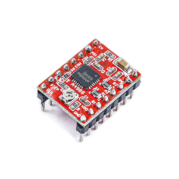
The A4988 stepper motor driver is intended to drive a bipolar stepper motor. Only by two pins, you can control the rotation direction and rotation steps. Each signal sent by the spin step pin, the motor rotates one step. The key features are:
- This driver has 200 steps per revolution in full step (1.8 degrees per step).
- Allowable continuous current per phase without cooling: 1A
- Maximum current per phase with cooling: 2A
- Motor voltage: 8 to 35 V
- The minimum allowed pulse width on the STEP pin is 1 us
- Overcurrent protection
Note
The number of steps that this stepper motor has in a full step is 16 steps.
You can download the datasheet of this module here.
A4988 Stepper Motor Driver Pinout
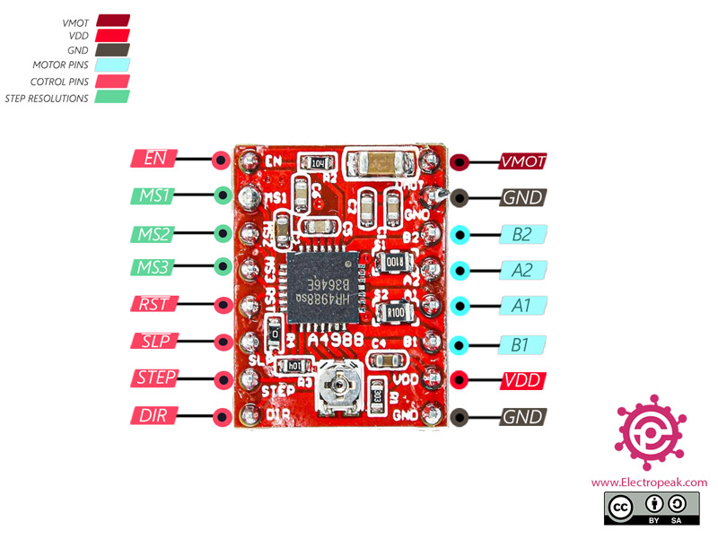
This Module has the following pins:
Power Supply Pins:
- VDD: Module power supply – 3-5.5 V
- GND: Ground
- VMOT: Motor power supply – 3-5.5 V
Note
You can use a capacitor to protect the driver from VMOT voltage sparks.
Motor Coil Pins:
- 1A: Pin 1 for motor coil 1
- 1B: Pin 2 for motor coil 1
- 2A: Pin 1 for motor coil 2
- 2B: Pin 2 for motor coil 2
Pins for controlling power states:
- DIR: Digital signal to control the direction of motor movement
- STEP: Digital signal to control rotation steps
- SLP: This signal is used when the motors are not in use – Active-Low
- RST: Reset signal – Active-Low
- EN: When this signal is activated, the driver outputs are disabled.
Step resolution Selection Pins:
- MS1: Step resolution pin 1
- MS2: Step resolution pin 2
- MS3: Step resolution pin 3
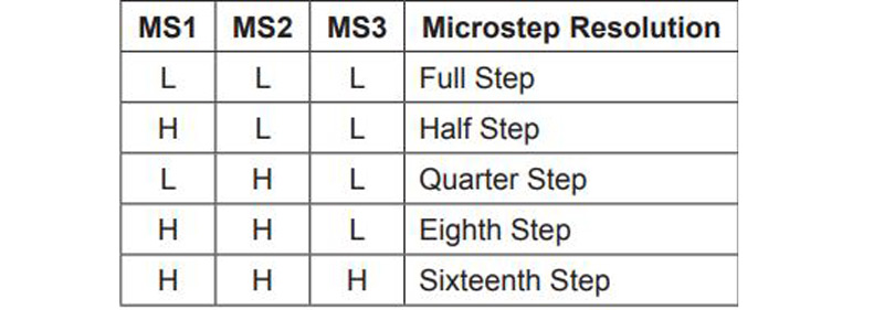
By changing these 3 pins, you can change the step from full step to step 1/16. The table below shows these changes:
You can see the pinout of this module in the image below.
Required Materials
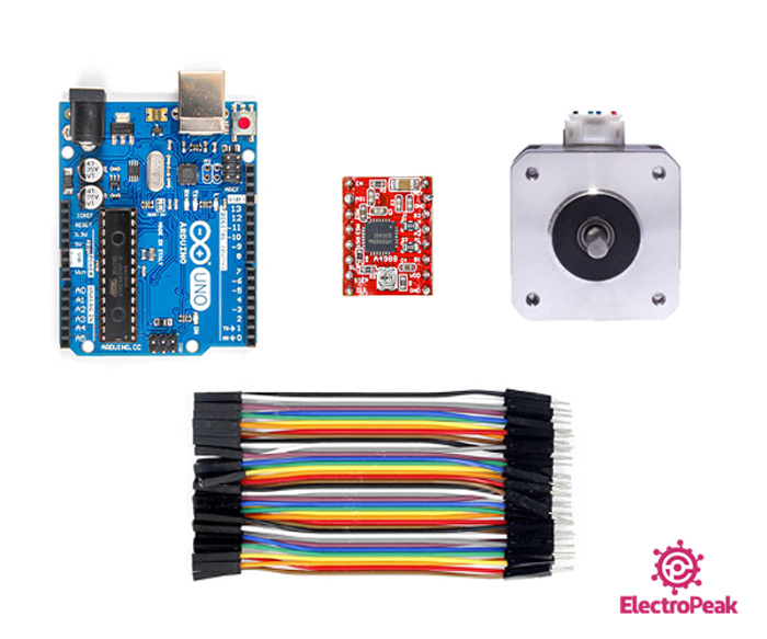
Hardware Components
Software Apps
Note
Be careful to interface this motor by A4988 driver, you need a power supply (adapter, battery, etc.) higher than 8V. The power supply is not listed above. Prepare one yourself.
Interfacing A4988 Stepper Motor Driver with Arduino
Step 1: Circuit
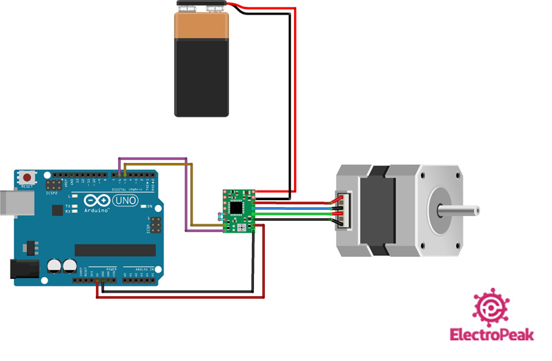
The following circuit show how you should connect Arduino to A4988 module. Connect wires accordingly.
Note
The SLP and RST pins are connected.
Step 2: Current Limit
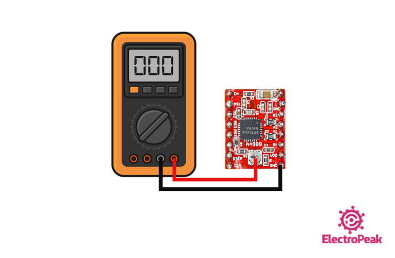
Before connecting the motor, we must apply the driver current limit to make sure that this current does not damage the driver and the motor. This current is measured by measuring the potentiometer reference voltage as in the following formula. However, it cannot be said that this relationship is always true.
Current Limit = VRef × 2
First connect the positive side of multimeter to potentiometer and the negative side of multimeter to GND. The voltage which is measured is VRef. Multiplying it by 2 gives us the current limit. Furthermore, according to the datasheet, if the driver is in full step mode, the coil current is 70% of the limited current:
Winding Current = Current Limit × 0.7
Step 3: Code
Upload the following code to your Arduino.
    /*
  A4988-Reprap-Stepper-Driver
  made on 29 Nov 2020
  by Amir Mohammad Shojaee @ Electropeak
  Home

*/

#define DIR 6
#define STEP 5

void setup(){
  pinMode(DIR,OUTPUT);
  pinMode(STEP,OUTPUT);
}
 void loop(){
  digitalWrite(DIR,HIGH);
  for(int x=0;x<100;x++){
    digitalWrite(STEP,HIGH);
    delayMicroseconds(500);
    digitalWrite(STEP,LOW);
    delayMicroseconds(500);
  }
  delay(1000);
  digitalWrite(DIR,LOW);
  for(int x=0;x<100;x++){
    digitalWrite(STEP,HIGH);
    delayMicroseconds(500);
    digitalWrite(STEP,LOW);
    delayMicroseconds(500);
  }
  delay(1000);
 }
First, we define pins 5 and 6 as STEP and DIR pins. Then, with a simple code with the for loop, the motor rotates half step clockwise and half step counter-clockwise.
