
Overview
Have you ever wanted to use 2 sensors with the same I2C address at the same time, not knowing what to do? Faced some serious challenges in doing that?
In a lot of projects, we have used different modules and sensors that support I2C communication protocol. Sometimes, we have interfaced some I2C modules with a microcontroller in our projects. If they all have different I2C addresses, we could easily interface them, facing no serious trouble. But, if 2 or more of the modules had the same I2C address, we would face some apparently unsolvable problems in using them all. This problem is a serious one which we all have definitely come across with at least once. If you’re having the same problem, this tutorial can be helpful for you.
Generally speaking, this problem can be solved in both software and hardware. In this tutorial, we are going to present a hardware solution for this problem. In a nutshell, we are going to add the TCA9548A I2C Multiplexer to the project and expand the I2C addresses of the modules with the same I2C address.
What You Will Learn
The real challenge while working with I2C communication protocol is interfacing different I2C devices with the same address to Arduino or any other microcontroller.
In this article, we first interface the two temperature & humidity sensors GY-21 and LM75 which have different I2C addresses with Arduino and use an OLED to display the temperature each of them measures. We do that by combining their libraries and then display the temperature on the OLED.
Then we will add the I2C expansion module TCA9548A to the circuit. But in this stage, we use the sensors GY-21, SHT20 and HTU21D, which all have the same I2C address. We will make some changes in the code and display the temperature measured by each sensor on the OLED.
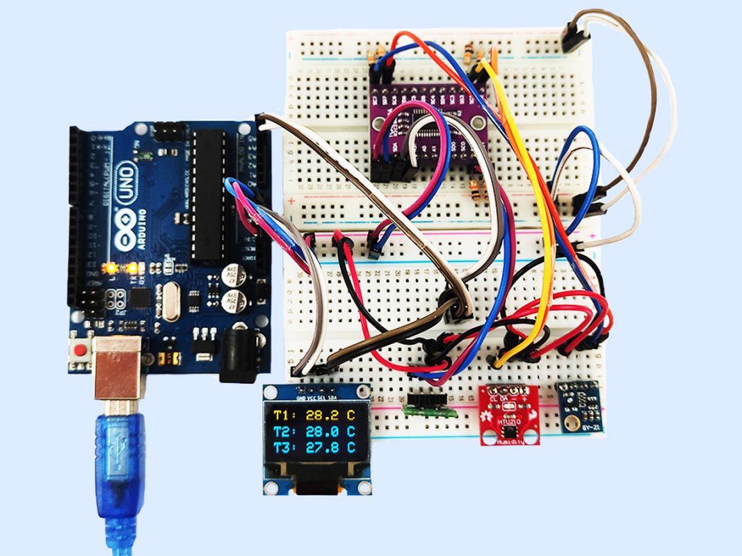
The image below is a preview of the final circuit. At the end of this tutorial, you will be able to display the temperature measured by these 3 sensors having the same I2C address on an OLED.

What Is I2C Communication Protocol, and How Does It Work?
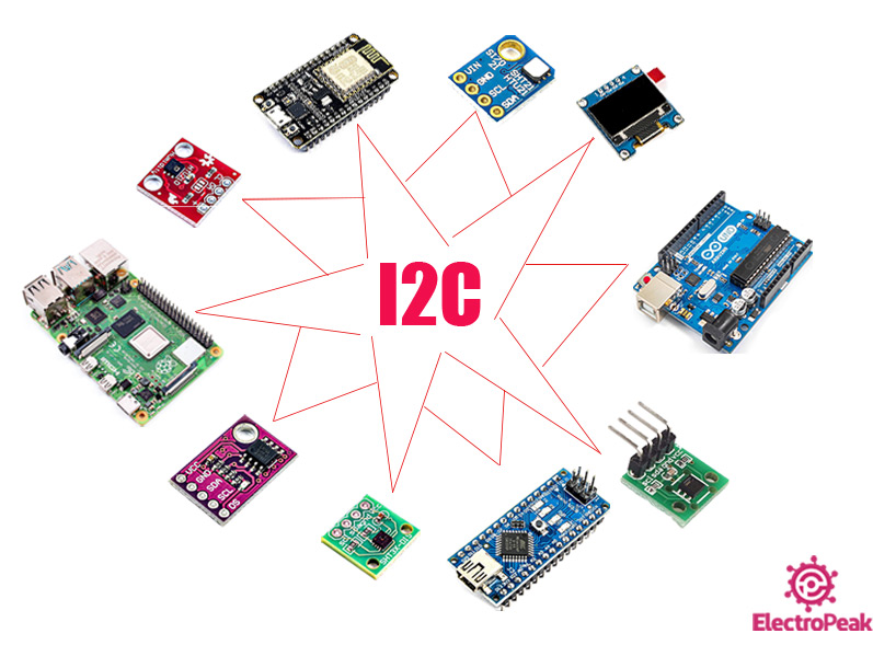
I2C, short for Inter-Integrated Circuit, is a communication protocol which can also be referred to with the short term IIC. This communication protocol is widely used in microcontrollers. In this communication, masters and slaves (Masters are usually the main components like microcontrollers and Slaves are sensors, modules and other components used in the circuit.) communicate through 2 lines:
- SDA (Serial Data): The line to transmit and receive data between the Master and Slave
- SCL (Serial Clock): The line to send the clock
Note
In the Arduino Uno, the pins A4 and A5 are the SDA and SCL, respectively.
In other boards and microcontrollers, these pins might differ. In that case, you can easily figure out the I2C pins by checking the datasheet of that specific microcontroller.
The most important features of the I2C communication protocol are the following:
- It’s not so fast (But fast enough for most applications)
- Suitable for short distances (e.g. maximum distance in 100KHz is 1 meter)
- Synchronous communication
- Data is transmitted serially
- Logic level can be both 3.3V and 5V
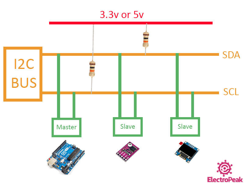
In the I2C communication protocol, there are two types of devices that connect to the I2C bus: The master and the slave. In this protocol, multiple slaves can be connected to a single master, like a microcontroller. And also, a single slave can be controlled and monitored by multiple masters, but only one of the masters can be active at a time. Each master can select which slave to communicate with. This selection is done through the slave’s 7-bit addresses (10-bit in some cases). So, there can be approximately 128 slave devices connected to the I2C bus. So, in other words, each slave has its own specific I2C address and there is no address for the masters.
The data transmitted on the I2C bus, synchronized by clock line, SCL. The master is responsible for the synchronization.
Note
The 2 SDA and SCL pins need to pulled-up in the circuit. At high speeds like 400kbps, a 2KΩ resistor is enough and at lower speeds like 100kbps, a 10KΩ resistor needs to be used.
How I2C Communication Protocol Works
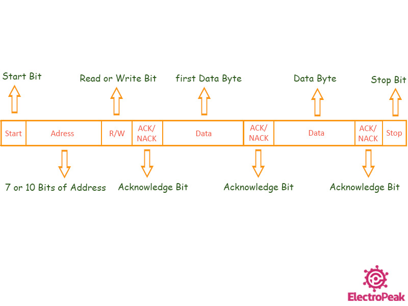
The data being transmitted between 2 devices on the SDA line consists of the following parts:
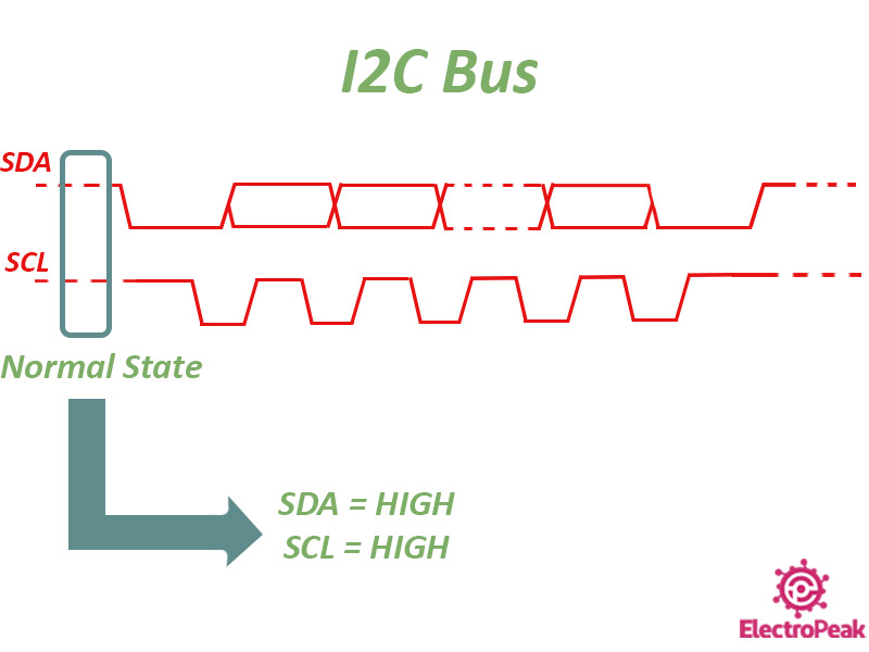
- Start: At first, the SDA line voltage drops from High to Low level. Then, the same thing goes for the SCL line, too.
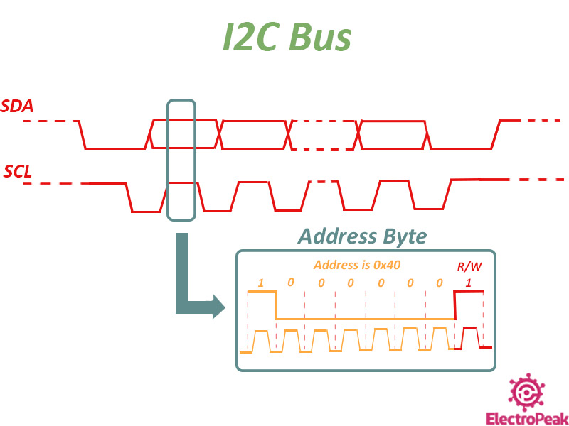
- Address: Including 7 bits (10 bit in some cases) is the I2C address of the module that the master intends to communicate with. These 7 bits (the address) is always sent from the master toward the slaves. After the address is sent, each slave compares it to its own address and in case it matches, the module will send a single bit (ACK Bit) in Low level to the master.
- R/W Bit: This bit, which is sent alongside the 7-bit address (it’s the LSB) determines whether the master is the transmitter or the receiver. If this bit is in High level, the master is the receiver, and vice versa.
- ACK/NACK Bit: Once each 8-bit data is received by the Master or Slave, this bit specifies whether the data has been properly received. If the receiver properly receives the data, it’s called the “Acknowledge” state and a bit with Low level will be sent through the SDA line.
- Date: Once the ACK Bit sent from the slave is received by the master, the first byte of data is prepared to be sent. Pay attention that at the end of each data transition, the receiver must put the ACK bit in Low level to indicate full proper transition.
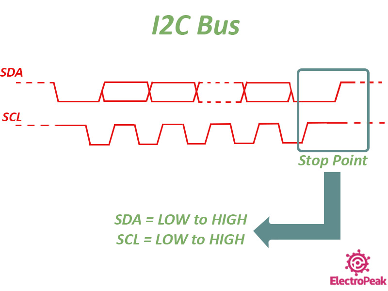
- Stop: After the completion of all data, at first, the SCL line changes from Low to High and then the SDA line will change from High to Low.
Note
There is no limit on the number of the bytes of the data you want to transmit.
How Data is transmitted in the I2C Bus
Data and information are constantly transmitting in the I2C bus to and from the masters and slaves. As already mentioned, the master starts the communication in the bus and also sources the clock pulse. The data communication between two devices in the I2C bus consists of the following stages:
Stage Zero
At this level, the data transmission has not started yet and both the SDA and SCL lines are in High level.
Stage One
This stage is actually the beginning of the data transmission. This stage is started by the master. At first, the SDA lines changes from High to Low level and then the same thing happens for the SCL line.

Stage Two
The 7 bits of information about the address of the slave alongside with the R/W bit is transmitted. So, the whole information sent in this stage is a single Byte. For simplicity in the images, the data transfer is displayed in Byte. But the data is transferred bit by bit in reality. For example, suppose the master wants to do the “Read” operation from the address “0x40”. The data transfer is as follows:t
Stage Three
Once the Byte of the data consisting the I2C address and the R/W bit is sent, the module whose I2C address matches the value sent, will send back the ACK bit in the Low voltage level. Then, it will wait for the first byte of data sent from the transmitter. Supposing that the slave is the receiver (R/W bit = High), and the slave wants to transmit the data “0x35” to the master:
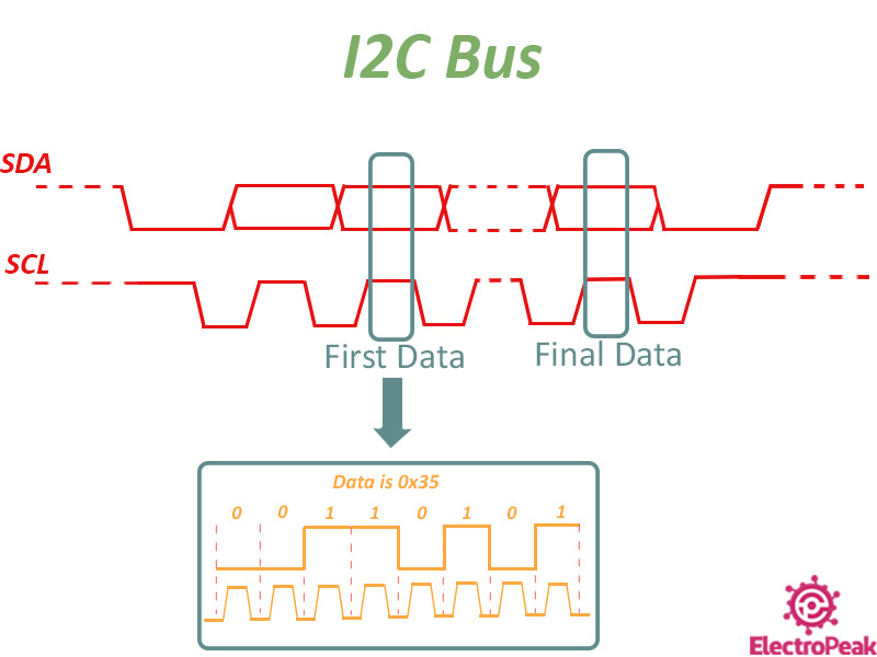
One or more bytes of data can be transferred in each communication. These bytes are sent bit by bit synchronously by the clock. At the end of each byte, the receiver sends the ACK bit in Low level back to the transmitter to acknowledge it has properly received the data.
When the last byte of information is sent, the SDA line will be in Low voltage level and the SCL line will stay High.
Note
The last byte of data is no different from the previous bytes.
If the slave is the transmitter, the master has already determined how many bytes of data it is expecting to receive. So, when the last byte of data is sent, the master would know.
The number of the bytes depend on the slave.
Stage Four
This is the final stage of the data transfer. For that to happen, both the SDA and SCL lines change from High to Low level and stay in that level.
Required Material
In order to do this project completely, you will need some I2C modules and some other components, which are listed below.
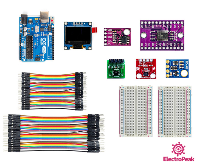
Hardware Components
Software Apps
Interface Two Temperature Sensors with Different I2C Addresses
At first and before working with sensors with the same I2C address, we are going to work with some sensors with different I2C addresses to get more familiar with the subject. Then we go to the main part, which would be working with sensors sharing the same I2C address.
Step 1: Circuit
The following circuit shows how you should connect the two temperature & humidity sensors GY-21 and LM75 and also the OLED display to the Arduino Board. Connect wires accordingly.
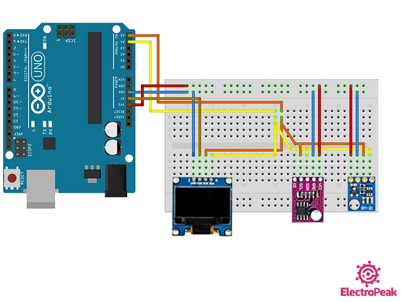
As you can see in the image above, all three module support I2C communication protocol. A4 and A5 pins of the Arduino Board are the SDA and SCL pins, respectively. These two pins differ from microcontroller to microcontroller, and even from Arduino Board to Arduino Board. For more information, you can check this link.
Step 2: Finding the I2C Addresses of the Modules
You can find out the I2C addresses of the three modules connected to the Arduino Board using the “Wire” library and the “i2c_scanner” example.
Upload the code below to your Arduino Board.
/*
  Made on 18 may 2021
  Home
  based on Arduino Library
*/

#include <Wire.h>

void setup() {
  Wire.begin();

  Serial.begin(9600);
  while (!Serial); // Leonardo: wait for serial monitor
  Serial.println("\nI2C Scanner");
}

void loop() {
  int nDevices = 0;

  Serial.println("Scanning...");

  for (byte address = 1; address < 127; ++address) {
    // The i2c_scanner uses the return value of
    // the Write.endTransmisstion to see if
    // a device did acknowledge to the address.
    Wire.beginTransmission(address);
    byte error = Wire.endTransmission();

    if (error == 0) {
      Serial.print("I2C device found at address 0x");
      if (address < 16) {
        Serial.print("0");
      }
      Serial.print(address, HEX);
      Serial.println("  !");

      ++nDevices;
    } else if (error == 4) {
      Serial.print("Unknown error at address 0x");
      if (address < 16) {
        Serial.print("0");
      }
      Serial.println(address, HEX);
    }
  }
  if (nDevices == 0) {
    Serial.println("No I2C devices found\n");
  } else {
    Serial.println("done\n");
  }
  delay(5000); // Wait 5 seconds for next scan
 }
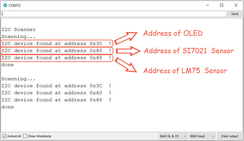
After successfully uploading the code above, open the Serial Monitor and see their I2C addresses. The result is as follows:
Step 3: The Main Code and Results
In the previous step, we found out the I2C addresses of each of the modules. Now, we are going to combine their libraries and display the temperature measured by each of the two temperature sensors and display it on the OLED. For that, upload the following code on your Arduino Board:
/*
  Made on 1 june 2021
  By Amirmohammad Shojaei
  Home
*/
#include <Wire.h>

#include "Adafruit_Si7021.h"     //add GY-21 si7021 Library
Adafruit_Si7021 sensor = Adafruit_Si7021();


#include <Temperature_LM75_Derived.h>  //add LM75 Library
Generic_LM75 LM75;

#include <Adafruit_SSD1306.h>
#define SCREEN_WIDTH 128 // OLED display width, in pixels
#define SCREEN_HEIGHT 64 // OLED display height, in pixels
// Declaration for an SSD1306 display connected to I2C (SDA, SCL pins)
#define OLED_RESET     4 // Reset pin # (or -1 if sharing Arduino reset pin)
Adafruit_SSD1306 display(SCREEN_WIDTH, SCREEN_HEIGHT, &Wire, OLED_RESET);

void setup()
{
  Serial.begin(9600);
  Wire.begin();
  delay(100);


  display.begin(SSD1306_SWITCHCAPVCC, 0x3C); // Initialize OLED

}

String T_LM75;
String T_GY21;

void loop() {

  float T_GY21_S = sensor.readTemperature(); //Temperature of GY21 Sensor
  T_GY21= String(T_GY21_S);
  T_GY21.remove(4,1);        //remmove one Decimal

  float T_LM75_S = LM75.readTemperatureC();   //Temperature of LM75 Sensor
  T_LM75= String(T_LM75_S);
  T_LM75.remove(4,1);        //remmove one Decimal

  Serial.print("T-GY21: ");
  Serial.print(T_GY21);       //print value of T-GY21 on Serial Monitor
  Serial.print("C");

  Serial.print("   T-LM75: ");
  Serial.print(T_LM75);        //print value of T-LM75 on Serial Monitor
  Serial.println("C");

  display.clearDisplay();
  display.setTextSize(2);
  display.setTextColor(SSD1306_WHITE); // Draw Yellow text
  display.setCursor(1, 1);     // Start at top-left corner
  display.print("T1: ");
  display.print(T_GY21);
  display.println(" C");

  display.setTextSize(2);
  display.setTextColor(SSD1306_WHITE); // Draw blue text
  display.setCursor(1, 35);     // Start at (1,35) poin
  display.print("T2: ");
  display.print(T_LM75);
  display.println(" C");
  display.display();
  delay(1000);
}
At the beginning of the code, the libraries of the two temperature & humidity sensors and the OLED display are included. In the main loop of the code, we get and save the temperature values measured by each sensor. Then, to better display the numbers on the OLED, one of the decimals of each value is removed, and the values are both displayed with one decimal. At the end of the code, the temperature values are displayed on the OLED using its library.
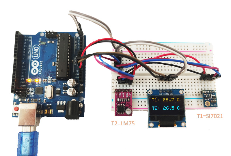
In practice, the output of the code is as follows. The temperature measured by the two sensors LM75 and GY-21 are displayed on the OLED.
Interface Three Temperature Sensors with the Same I2C Address
In this section, we are going to display the temperature measured by the three temperature and humidity sensors GY-21, SHT20 and HTU21D which have the same I2C address. If more than one sensor share the same I2C address, the Arduino Board is no longer able to communicate with them. In such cases, we can use the TCA9548A module to solve this problem and actually expand the I2C pins.
Before getting to the main program, we better know a little about the TCA9548 module.
TCA9548 I2C Expansion Board
Using this module, you can expand a single I2C address up to 8 I2C addresses. The I2C address of this module itself is “0x70” by default, which can be modified using its A0-2 pins. This means that you can use 8 of these modules at the same time. And that means that you will be able to expands the I2C pins up to 64.
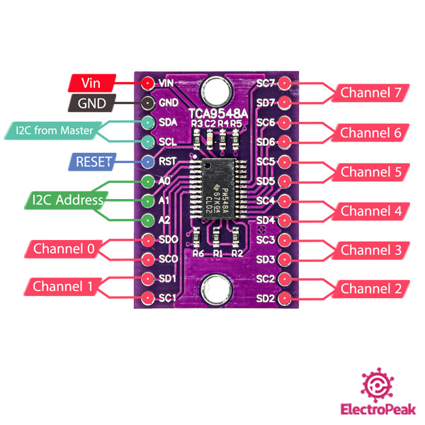
You can see the pinout of the TCA9548 I2C Expansion Board in the image above. A few points are worth mentioning:
- The module operating voltage is 3-5.5 volts.
- The “RESET” pin can be used to reset the module -not frequently used-
- You can change the module I2C address from “0x70” to “0x77” using the A0-2 pins. (So, we can connect up to 8 of these modules to a single Arduino Board.)
- The SDA and SCL pins are connected to the I2C bus.
- This module has 8 output channels.
Note
The input SDA and SCL pins of the module are pulled-up. But you need to pull-up the output I2C channels of the module on your own.
Finding the I2C Addresses of the Modules Before Connecting the TCA9548A Module
Before setting up the main and final circuit, we are going to connect the three temperature sensors and also the OLED display to the I2C pins of the Arduino Board and see their I2C address.
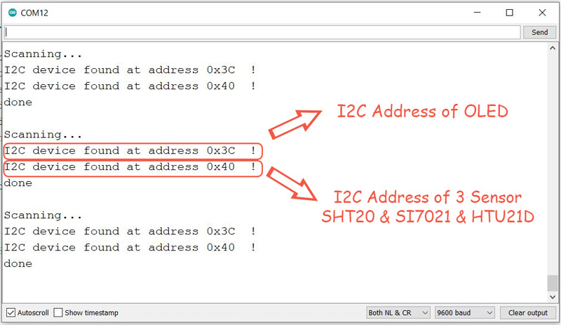
As you can see, all three temperature sensors have the same I2C address “0x40”, so they can’t be used altogether.
Now, we are going to add the TCA9548A I2C Expansion module to the circuit and follow the steps below to solve the problem:
Step 1: Circuit
First, we set the circuit up by connecting the 3 temperature sensors SHT20, HTU21D and GY-21, the TCA9548A module and the OLED display to the Arduino Board as follows:
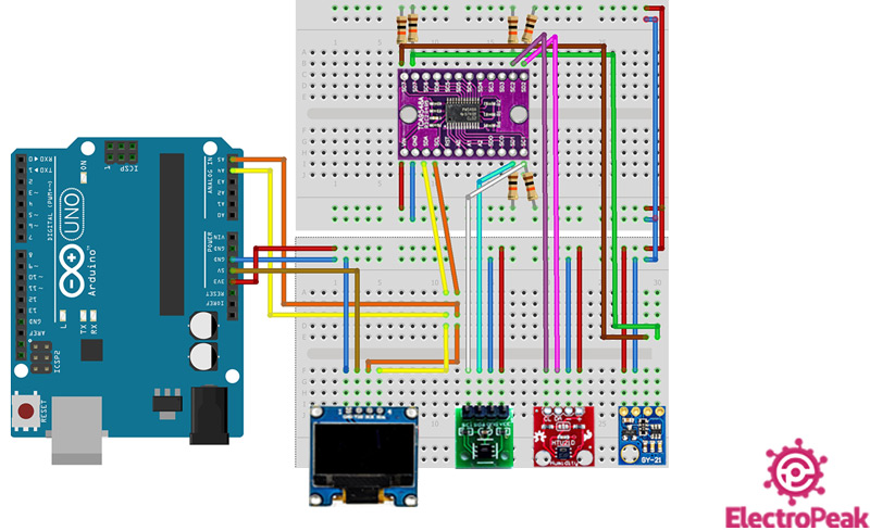
The final circuit has been represented in the image above. In this circuit, the 3.3v voltage level has been used for the temperature sensors for more safety. Also, the output I2C channels of the TCA9548A module have been pulled up.
Step 2: The Main Code & Results
In this code, we will do the same as we did with the previous circuit where we had only 2 temperature sensors, with the only difference is that we are going to deal with 3 temperature sensors this time and the TCA9548A module is also added to the circuit. When we add the TCA9548A I2C Expansion module:
- The I2C addresses of the modules connected to it become a subset of the I2C of this module.
- And whenever we want to communicate with a module, we need to use the I2C address of the channel the module is connected to.
To do that, we define a function named “TCA9548A()” in the new code, and the input of that function will be the channel number we want to activate. Now, whenever we want to work with the library of a module, we should include its library beforehand and use the number of the channel as its input. To make that clear, let’s take an example. For example, when we want to use the function “sensor.readTemperature()” to save the temperature measured by the GY-21 sensor, we need to call the function “TCA9548A(7)” –Since the GY-21 is connected to channel number 7 of the TCA9548A module-.
Now upload the following code on the Arduino Board:
/*
  Made on 18 may 2021
  By Amirmohammad Shojaei
  Home

*/
#include <Wire.h>

#include "SparkFunHTU21D.h"    //add HTU21D Library
HTU21D myHumidity;

#include "Adafruit_Si7021.h"     //add GY-21 si7021 Library
Adafruit_Si7021 sensor = Adafruit_Si7021();

#include "DFRobot_SHT20.h"       //add SHT20 Library
DFRobot_SHT20 sht20;

#include <Adafruit_SSD1306.h>    //add SSD1306 OLED Library
#define SCREEN_WIDTH 128 // OLED display width, in pixels
#define SCREEN_HEIGHT 64 // OLED display height, in pixels
#define OLED_RESET     4 // Reset pin # (or -1 if sharing Arduino reset pin)
Adafruit_SSD1306 display(SCREEN_WIDTH, SCREEN_HEIGHT, &Wire, OLED_RESET);

void TCA9548A(uint8_t bus) //function of TCA9548A
{
  Wire.beginTransmission(0x70);  // TCA9548A address is 0x70
  Wire.write(1 << bus);          // send byte to select bus
  Wire.endTransmission();
}

void setup()
{
  Serial.begin(9600);
  Wire.begin();
  delay(100);

  TCA9548A(2);
  myHumidity.begin();        //Initialize HTU21D Sensor

  TCA9548A(1);
  sht20.initSHT20();                         // Initialize SHT20 Sensor
  delay(100);
  sht20.checkSHT20();                        // Check SHT20 Sensor

  display.begin(SSD1306_SWITCHCAPVCC, 0x3C); // Initialize OLED

}

String T_SHT20;
String T_HTU21D;
String T_GY21;

void loop() {

  TCA9548A(1);
  float T_SHT20_S = sht20.readTemperature();   //Temperature of SHT20 Sensor
  T_SHT20= String(T_SHT20_S);             //remmove one Decimal
  T_SHT20.remove(4,1);

  TCA9548A(2);
  float T_HTU21D_S = myHumidity.readTemperature();   //Temperature of HTU21D Sensor
  T_HTU21D= String(T_HTU21D_S);          //remmove one Decimal
  T_HTU21D.remove(4,1);

  TCA9548A(7);
  float T_GY21_S = sensor.readTemperature();        //Temperature of GY21 Sensor
  T_GY21= String(T_GY21_S);            //remmove one Decimal
  T_GY21.remove(4,1);

  Serial.print("T-SHT20: ");
  Serial.print(T_SHT20);      //print value of T-SHT20 on Serial Monitor
  Serial.print("C");

  Serial.print("   T-HTU21D: ");
  Serial.print(T_HTU21D);         //print value of T-HTU21D on Serial Monitor
  Serial.print("C");

  Serial.print("   T-GY21: ");
  Serial.print(T_GY21);           //print value of T-GY21 on Serial Monitor
  Serial.println("C");


  display.clearDisplay();
  display.setTextSize(2);
  display.setTextColor(SSD1306_WHITE); // Draw Yellow text
  display.setCursor(1, 1);     // Start point
  display.print("T1: ");
  display.print(T_SHT20);
  display.println(" C");


  display.setTextSize(2);      // Normal 1:1 pixel scale
  display.setTextColor(SSD1306_WHITE); // Draw Blue text
  display.setCursor(1, 22);     // Start point
  display.print("T2: ");
  display.print(T_HTU21D);
  display.println(" C");


  display.setTextSize(2);
  display.setTextColor(SSD1306_WHITE); // Draw Blue text
  display.setCursor(1, 45);     // Start point
  display.print("T3: ");
  display.print(T_GY21);
  display.println(" C");
  display.display();

  delay(1000);
}
At the beginning of the code, the libraries of the 3 temperature sensors and also the OLED display are included. After including the libraries, we define the function “TCA9548A”. Then, we do as before. In the main loop of the code, the temperature measured by each sensor is saved. Next, to better display the numbers on the OLED, one of the decimals of each value is removed, and the values are all displayed with one decimal.
The GY-21, HTU21D and SHT20 sensors are connected to the channels 7, 2 and 1 of the TCA9548A module, respectively. The output is as follows in practice. The ambient temperature measured by each sensor is displayed separately on the OLED:

What’s Next?
After completing this tutorial, you can experience new challenges related to this tutorial:
- I2C Communication between two Arduino Boards
- Using two TCA9548A simultaneously
- Using two OLED displays sharing the same I2C address
- Setting up a circuit including 2 masters and multiple slaves sharing the same I2C bus
