
Product added to cart

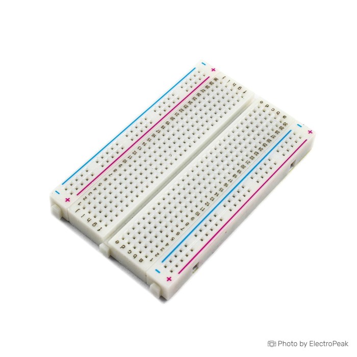
400 Points Half Size Breadboard - 5.5x8.5cm
$0.5600
In stock
SKU
CAB-01-002
Volume discounts:
- +50 7 % $0.5200
- +100 9 % $0.5100
- +300 13 % $0.4900
- +500 16 % $0.4700
- +1000 20 % $0.4500
Ships in 2-3 business days, then:
Free delivery in 12-15 days by Tracked Economic Shipping on orders over $100.
Free delivery in 7-10 days by Express Shipping on orders over $300.
More shipping info

Shop with confidence Learn More
 SYB-500 Breadboard - 200x240x8.5mm Previous
400 Point Breadboard Review: Compact Solderless Prototyping
The 400 Points Half Size Breadboard is a reusable 85mm x 55mm platform for temporary circuit assembly, testing, and early-stage prototyping. It provides a compact solderless workspace for circuits using standard 2.54mm-pitch hardware and 21 to 26 AWG solid wires. For designs that need substantially more connection points, the SYB-120 Breadboard (700 points) offers a higher-capacity layout. Our selection of solderless breadboards also includes full-size and modular formats.
Specifications of 400 Points Half Size Breadboard - 5.5x8.5cm
- Holes: 400 holes
- Terminal strip: 300 tie-point terminal strip
- Distribution strip: 100 tie-point distribution strip
- Pitch: 2.54mm
- Color: White
- Material: ABS plastic
- Size: 8.5x5.5cm
- Body dimensions: 85mm x 55mm
- Spring clips: Phosphor bronze nickel-plated spring clips
- Wire compatibility: Supports 21 to 26 AWG wires
400 Point Breadboard Specifications and Layout Explained
The right breadboard depends on how your components map across the contact grid and whether its dimensions fit your workspace. This board's 400 holes are divided into two working areas: a central 300 tie-point terminal strip for mounting ICs and passive components, plus a 100 tie-point distribution strip for routing power rails and shared reference lines.
| Specification | Listed Value | Why It Matters |
|---|---|---|
| Tie-Point Capacity | 400 holes (300 terminal, 100 distribution) | Provides sufficient connection points for compact breakout boards and discrete components while keeping the working footprint small. |
| Grid Pitch | 2.54mm (0.1 in) | Matches industry-standard dual in-line package (DIP) pin spacing, standard headers, and through-hole electronic modules. |
| Body Dimensions | 85mm x 55mm (8.5x5.5cm) | Occupies minimal desktop or bench space, making it straightforward to position directly alongside microcontrollers or test instruments. |
| Contact Material | Phosphor bronze nickel-plated spring clips | Maintains mechanical spring tension to grip inserted leads securely during temporary experimentation. |
| Body Material | White ABS plastic | Provides rigid physical insulation between rows and structural housing for the internal contact clips. |
| Wire Compatibility | 21 to 26 AWG | Ensures reliable contact without over-stretching the internal clips with thick leads or losing grip on overly thin wire. |
| Alignment Markings | Color-coded coordinates | Simplifies circuit tracing and helps identify row coordinates when translating schematics onto the physical layout. |
For a tiny sensor test or a single logic gate where space is severely constrained, the smaller SYB-170 Mini Breadboard (170 points) is an ultra-compact 47x35mm alternative.
400 Point Breadboard Setup, Wire Compatibility and Accessories
This board uses solderless mechanical retention, so you do not need soldering, specialized hand tools, or software drivers to begin assembling a circuit. The setup process is direct and repeatable:
- Insert component leads directly into the tie-points using gentle, steady pressure. Avoid forcing thick or bent pins into the holes to preserve the internal spring clips.
- Use jumper wires within the supported 21 to 26 AWG range to make temporary connections between rows and distribution rails.
- Check component placement and coordinate alignment against your wiring diagram.
- Power and test the circuit, then modify component positions or jumper routes as your experiment develops.
The breadboard is a passive mechanical platform. Active circuits need wiring and external hardware to function, so add the complementary items required for your particular build.
Required Accessories
- Interconnect wiring: Jumper wires are required to route signals between tie-points and connect external hardware. Flexible Male/Male Jumper Wires 40 -10/20/30 cm plug directly into the 2.54mm breadboard sockets.
- Circuit components and power: Resistors, semiconductors, integrated circuits, and an appropriate DC power supply are necessary for any functional circuit build (sourced separately according to your schematic).
Recommended Accessories
- Pre-formed wiring assortment: To keep compact layouts clean and legible, the Breadboard Jumper Wire Kit - 140 Pieces provides pre-bent, solid-core jumpers that sit flush against the ABS body.
Optional Accessories
- Module interface wiring: For breadboard assemblies connected to boards that use male pin headers, Male/Female Jumper Wires 40 - 10/20/30 cm allow direct connections between the breadboard and external header pins.
- Controller board: For programmable logic or automated testing, an external development platform such as an Arduino Uno R3 (Clone) provides programmable I/O lines for breadboard prototyping experiments.
400 Point Breadboard vs 830-Point and Larger Breadboards
Breadboard format is a balance between required tie-point capacity and physical footprint. This 400-point board provides a compact half-size work area. Larger boards provide more room for complex projects with extensive IC counts or multi-voltage power rails.
| Model | Total Points / Holes | Terminal vs Distribution Allocation | Body Dimensions | Key Physical Features |
|---|---|---|---|---|
| 400 Points Half Size Breadboard | 400 holes | 300 terminal / 100 distribution | 85mm x 55mm | Compact half-size form factor; color-coded coordinates; white ABS housing. |
| 830-Point Breadboard (16.5x5.4cm) | 830 holes | Standard full-size split | 165mm x 54mm x 8.5mm | Vertical column links and upper/lower horizontal power rails for full-length layouts. |
| MB-102 Breadboard (830 points) | 830 points | 630 terminal / 200 power distribution | 165mm x 55mm x 10mm | Full-size layout with 200 power-distribution tie-points; rated for 3A current handling. |
| SYB-120 Breadboard (700 points) | 700 holes | 600 terminal / 100 distribution | 175mm x 46mm x 8.5mm | Slim elongated profile with phosphor bronze nickel-plated spring clips and coordinate markings. |
| SYB-500 Breadboard (2800 points) | 2,800 tie-points | Four 700-point sections | 240mm x 200mm x 8.5mm | Large-scale test surface with two integrated external power input binding points. |
If your design outgrows 400 tie-points, a standard 830-hole format adds terminal columns and extended distribution buses without changing your prototyping workflow.
400 Point Breadboard Limitations and Prototype Alternatives
A solderless breadboard is intended for rapid assembly, component verification, and iterative modification. Its contacts rely entirely on mechanical spring tension, so it is not built for permanent field installations, high-vibration environments, or high-reliability end-use hardware. The 400 total tie-points also set a physical limit on circuit complexity. Large microcontrollers or multi-stage analog circuits will quickly consume the 300 terminal points.
Once you have validated a circuit on a solderless board and need a durable, semi-permanent prototype, a hardwired perfboard is the standard engineering route:
- For larger circuits that need a sturdy layout, the Single-Sided Universal PCB (9x15cm) provides 1,400 to 1,440 plated holes on a single-sided fiberglass board for point-to-point soldered wiring.
- For compact assemblies, the Double-Sided Universal PCB (5x7cm) provides two-sided through-hole soldering pads to secure DIP and SMD components in a permanent assembly.
400 Point Breadboard FAQ
Is this a solderless breadboard?
Yes. Internal spring clips mechanically hold inserted wire leads and component pins, so no soldering is required for assembly, testing, or adjustments.
How many points does this 400 point breadboard have?
It has 400 total holes: a 300 tie-point terminal strip for component mounting and a 100 tie-point distribution strip for power and ground routing.
What size is the 400 Point Breadboard?
The board measures 8.5x5.5cm and has body dimensions of 85mm x 55mm.
What jumper wire size fits this half size breadboard?
The internal spring clips support 21 to 26 AWG solid wires and standard component pins manufactured for 2.54mm pitch spacing.
Are jumper wires included with the 400 Point Breadboard?
No, jumper wires are not included. Supply your own wiring, such as the Breadboard Jumper Wire Kit - 140 Pieces, to make connections across the board.
Can I reuse this solderless breadboard?
Yes. The board is completely reusable, so components and wires can be removed and inserted repeatedly while you test and modify different circuits.
Should I choose this 400 point breadboard or an 830-point breadboard?
Choose the 400-point model for small circuits or portable kits that need a compact 85mm x 55mm footprint. For designs with multiple ICs or longer power rails, use an 830-point layout or the 700-point SYB-120 Breadboard for additional working capacity.
Is a solderless breadboard suitable for a permanent project?
No. Solderless breadboards are for temporary testing and circuit experimentation. For permanent installations, transfer the circuit to a soldered universal PCB.
400 Point Breadboard Buying Checklist
Before placing your order, check that this board matches your prototyping needs:
- Ideal for: Compact temporary circuits, component testing, educational lab experiments, and early-stage prototypes using 21 to 26 AWG wires.
- Maybe for: Initial microcontroller projects, provided you already have or separately purchase compatible jumpers, components, and an external power source.
- Avoid if: Your schematic requires more than 400 tie-points, needs a miniature 170-point footprint, requires an expansive multi-board workspace, or demands a soldered permanent build.
| Verification Step | Requirement to Confirm |
|---|---|
| Circuit Capacity | Confirm that your design fits within 300 terminal tie-points and 100 distribution tie-points. |
| Available Bench Space | Verify that the 85mm x 55mm body footprint matches your enclosure or desktop layout. |
| Lead and Wire Gauge | Ensure that your component leads and jumper wires fall within the supported 21 to 26 AWG range. |
| Wiring Accessories | Jumper wires are not included; ensure you have appropriate male-to-male jumpers on hand. |
| Active Electronics | Check whether your build requires discrete components, a power supply, or a separate microcontroller such as an Arduino Uno R3 (Clone). |
| Assembly Type | Confirm that your prototype is temporary; if you require vibration-resistant permanent wiring, select a perfboard instead. |
| Format Alternatives | If you require higher connection capacity, browse our catalog of other breadboard capacities and formats before finalizing your checkout. |
| Order Details | Check current unit pricing and package quantity to meet your project or classroom volume requirements. |
Write Your Own Review

Please complete your information below to login.
Sign In
Create New Account