
Product added to cart

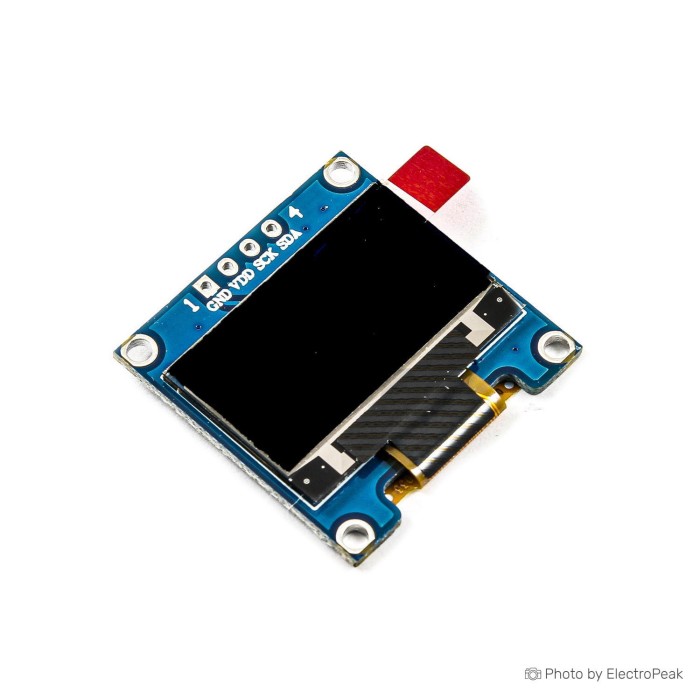
0.96 inch 128x64 I2C OLED Display Module, SSD1306 Driver
$1.2900
In stock
SKU
LCD-01-125
Volume discounts:
- +50 3 % $1.2500
- +100 5 % $1.2300
- +300 7 % $1.2000
- +500 9 % $1.1800
- +1000 10 % $1.1600
Ships in 2-3 business days, then:
Free delivery in 12-15 days by Tracked Economic Shipping on orders over $100.
Free delivery in 7-10 days by Express Shipping on orders over $300.
More shipping info

Shop with confidence Learn More
 2004 5V I2C Character LCD Display Module - Green Backlight Previous
0.96 Inch I2C OLED Module Review
The MC096GW is a compact monochrome OLED module with an SSD1306 driver, I2C communication, and a four-pin GND/VCC/SCL/SDA connection. It suits microcontroller interfaces that need short text, icons, status screens, menus, and simple graphics in limited space.
OLED pixels emit their own light, so no backlight circuit is required. The display is available in White, Blue, Yellow, and Blue and Yellow options. It is not intended for full-colour graphics, a large display area, or projects that specifically require SPI communication.
Specifications of 0.96 inch 128x64 I2C OLED Display Module, SSD1306 Driver
- Model: MC096GW
- Color: White, Blue, Yellow, Blue and Yellow
- Size: 0.96 inch
- Display Type: OLED
- Driver Chip: SSD1306
- Resolution: 64x128 pixels
- Module Communication: I2C
- Pins: 1-GND, 2-VCC, 3-SCL, 4-SDA
- Effective Display Size: 10.864 × 21.744 mm
- Module Size: 27 × 25 mm
- Viewing Angle: More than 160 degrees
- Operating Temperature: -20 to +70 °C
- Storage Temperature: -30 to +80 °C
- Operating Voltage: 3.3V / 5V
- Power Consumption: About 25 mA at full brightness
- Power Consumption: About 1.5 mA when off
The same display is available through a dedicated yellow/blue I2C OLED listing. This is an equivalent listing-format choice, not a different performance tier.
For full-colour RGB graphics, consider a full-colour TFT display approach with ST7735. It uses SPI, an LED backlight, and an 8-pin flat-cable connection. Buyers comparing screen technologies can also browse other display module formats.
0.96 Inch OLED Specifications and Size Explained
The effective display area is 10.864 × 21.744 mm, while the listed module size is 27 × 25 mm. Check both measurements against the enclosure opening, available PCB space, and mounting arrangement before ordering.
This 0.96 inch OLED provides a 128x64 display format for compact text, small icons, status values, and simple monochrome graphics. The active area suits a sensor dashboard, Wi-Fi status page, menu, or portable instrument readout, but it is too small for information-heavy screens that need large text or detailed graphics.
| Characteristic | Why it matters |
|---|---|
| 10.864 × 21.744 mm effective display size | Defines the visible area available for text and graphics, not the full board footprint. |
| 27 × 25 mm module size | Determines whether the board fits behind a panel, inside an enclosure, or on a prototype layout. |
| OLED display type | Self-emissive pixels do not need a backlight, which simplifies the display hardware. |
| More than 160 degrees viewing angle | Supports viewing from multiple positions, useful for bench instruments and shared status displays. |
| White, Blue, Yellow, or Blue and Yellow output | The display remains monochrome; select the colour option to suit the intended interface rather than expecting RGB graphics. |
Need a smaller display designed specifically as a WeMos D1 Mini shield? The smaller WeMos D1 Mini OLED shield uses a 0.66 inch 64x48 format. For a narrower screen layout in wearable or portable-device designs, use the narrow 128x32 OLED display.
SSD1306 I2C OLED Compatibility and Setup
This module communicates over I2C and exposes four connections: GND, VCC, SCL, and SDA. It fits Arduino, ESP32, ESP8266, STM32, RP2040, and similar microcontrollers with accessible I2C pins.
SSD1306 controller-family modules work with Adafruit_SSD1306 and Adafruit_GFX, U8g2, and SSD1306Ascii. Select an SSD1306-compatible configuration in the chosen library, then confirm the detected I2C address before assuming a wiring or hardware fault.
| Area | Compatibility |
|---|---|
| Display controller | SSD1306 driver chip. |
| Hardware interface | I2C through GND, VCC, SCL, and SDA. |
| Microcontroller platforms | I2C-capable Arduino, ESP32, ESP8266, STM32, RP2040, and similar microcontrollers. |
| Software libraries | Adafruit_SSD1306 with Adafruit_GFX, U8g2, and SSD1306Ascii are commonly used with SSD1306 controller-family modules. |
| Display type | Monochrome OLED; it is not a full-colour RGB display. |
| Interface limitation | This four-pin I2C module does not use the same connection format as SPI OLED modules or the 8-pin flat-cable ST7735 TFT display. |
First connection check
- Inspect the rear of the module and check the voltage-regulator area before selecting the supply voltage.
- Connect GND to GND, VCC to the selected supply, SCL to the controller SCL pin, and SDA to the controller SDA pin.
- Install an SSD1306-compatible library such as Adafruit_SSD1306 with Adafruit_GFX or U8g2.
- Run an I2C scanner and use the detected 7-bit address.
- Run a basic SSD1306 text example. Readable monochrome text or graphics across the panel confirms the basic connection.
An Arduino-compatible controller board provides the I2C host for a first test, while jumper wires for I2C wiring make the four required connections.
For fuller wiring details and example code, see the Arduino SSD1306 I2C setup guide and the guide to SPI and I2C OLED setup. If no image appears, scan the I2C bus before changing wiring or rewriting the display code.
0.96 Inch SSD1306 OLED Power, Address, and Limitations
The listed operating voltage is 3.3V / 5V. Inspect the rear voltage-regulator area before applying 5V, as the board-level regulator implementation is not confirmed. When the board implementation is unknown, 3.3V is the conservative connection choice.
Power consumption is listed as about 25 mA at full brightness and about 1.5 mA when off. Battery-powered designs should measure the actual module state and software configuration, because a blank display and a display-off state do not necessarily have the same current draw.
The MC096G* family commonly uses 0x3C in 7-bit notation. Some related boards can use 0x3D through an address option, but address-jumper availability for this board is not confirmed. An I2C scanner is the reliable way to identify the address installed on the received module.
Markings such as 0x78 or 0x7A can cause confusion. A 0x78 marking commonly represents the 8-bit write form of 0x3C, while most display libraries expect the 7-bit value 0x3C or 0x3D.
Default contrast may need software adjustment for the intended lighting conditions. Unexpected blank output or a two-pixel horizontal offset also warrants checking the controller marking and selected library configuration; generic OLED modules can differ from the expected controller family.
Exact batch-specific information for the regulator, I2C pull-ups, address option, controller marking, and PCB revision is not supplied. Long-term reliability data for this exact board is also not supplied; isolated reports from the wider generic OLED category are not enough to establish a product-wide failure pattern.
0.96 Inch I2C OLED vs SPI OLED
This 0.96 inch I2C OLED module uses GND, VCC, SCL, and SDA, keeping the connection to four pins. That arrangement suits projects where simple wiring and limited signal connections matter more than using a specific display bus.
The 0.96 inch SPI OLED uses SPI communication and is intended for projects that require SPI integration. Choose I2C when its four-pin connection suits the existing wiring; choose SPI when the project specifically needs SPI. Neither interface is universally better: available pins, update requirements, and the rest of the project wiring determine the fit.
For connection examples covering both interfaces, use this SPI versus I2C OLED connection guidance.
0.96 Inch OLED Accessories and Arduino Wiring
A working bench setup needs an I2C-capable microcontroller and four connections for GND, VCC, SCL, and SDA. A breadboard makes it easier to verify the pinout and display operation before fitting the module into an enclosure.
Required
- Arduino Uno R3 (Clone): provides an I2C host and runs the initial display test.
- Male/Female Jumper Wires 40 - 10/20/30 cm: make the four power and I2C connections.
Recommended
- SYB-500 Breadboard - 200x240x8.5mm: supports temporary wiring and pin verification before final installation.
- A multimeter: useful for checking the supply voltage and inspecting the rear-board regulator implementation before using 5V.
- An I2C scanner sketch or tool: confirms the actual address before code troubleshooting begins.
Optional
- Header pins: may be needed if the received module is not pre-soldered; soldering status is not supplied.
- External I2C pull-up resistors: may be needed if the bus does not operate correctly and the actual module lacks suitable onboard pull-ups.
- An enclosure or panel-mounting hardware: select these only after confirming the listed 27 × 25 mm board fit.
0.96 Inch OLED FAQ and Buying Checklist
Is this a 3.3V or 5V OLED module?
The listed operating voltage is 3.3V / 5V. Check the voltage-regulator area on the back of the board before using 5V, because the exact regulator implementation for this batch is not confirmed.
What I2C address should I use for this 0.96 inch SSD1306 OLED?
0x3C is the common 7-bit address for the MC096G* family. Related boards may use 0x3D through an address option, so run an I2C scanner to confirm the received module; 0x78 is commonly the 8-bit write form of 0x3C, not the value most libraries expect.
Why is my SSD1306 OLED blank or shifted horizontally?
Check the wiring, scan the I2C bus, confirm the 7-bit address, and verify the selected library configuration first. Persistent blank output or a two-pixel horizontal offset can indicate a controller-library mismatch in the broader generic OLED category.
How much current does this OLED draw?
The module is listed at about 25 mA at full brightness and about 1.5 mA when off. Battery projects should measure the actual module and software power state rather than treating the latter figure as confirmed deep-sleep current.
Can two 0.96 inch OLED displays share one I2C bus?
They can share one bus only when each display has a distinct usable address. Related modules may use 0x3C and 0x3D, but address-jumper availability for this board is not confirmed, so inspect and test the received modules before planning a two-display bus.
Does this OLED include jumper wires, headers, or a microcontroller board?
Package contents and header-pin soldering status are not stated. Plan on an I2C-capable microcontroller and four jumper-wire connections for a basic bench test.
Should I choose this I2C OLED or the SPI OLED version?
Choose this board for I2C through GND, VCC, SCL, and SDA; choose the SPI version when the project requires SPI integration. Available pins and the required interface determine the appropriate choice.
Purchase decision summary
- Ideal for: Compact Arduino, ESP32, ESP8266, STM32, RP2040, and similar microcontroller projects that need monochrome text, icons, status data, menus, and simple graphics through I2C.
- Maybe for: Battery-powered instruments, portable devices, and enclosure projects after confirming actual module power behaviour, regulator implementation, address, and physical fit.
- Consider another option if: The project needs full RGB colour, a larger display area, a dedicated WeMos D1 Mini shield, guaranteed batch-specific hardware documentation, or an SPI display interface.
Buying checklist
- ✓ Confirm that a 0.96 inch monochrome OLED suits the required interface.
- ✓ Confirm that the listed 27 × 25 mm module size and 10.864 × 21.744 mm effective display size fit the enclosure.
- ✓ Confirm that the controller board has accessible I2C SCL and SDA pins.
- ✓ Confirm that I2C, rather than SPI, fits the project wiring and update requirements.
- ✓ Confirm whether White, Blue, Yellow, or Blue and Yellow output matches the intended interface.
- ✓ Plan four connections: GND, VCC, SCL, and SDA.
- ✓ Check the rear-board regulator area before using 5V.
- ✓ Plan an I2C scanner for address confirmation.
- ✓ Allow for an SSD1306 library and a basic text example.
- ✓ Add a microcontroller board, jumper wires, and a breadboard if they are not already available.
- ✓ Do not assume headers, cables, or other package contents are included.
Buyers still deciding on screen size, colour, or display technology can compare other display technologies and formats.
| Model | MC096GW |
|---|---|
| Display Size | 0.96 |
| Display Size Range | 0.99 inch and smaller |
| Display Resolution | 128x64 |
| Display Driver | SSD1306 |
| Display Interface | I2C |
| Display Color Type | Monochrome |
| Touchscreen Type | None |
| Backlight Type | None |
| Viewing Angle (°) | > 160° |
| Operating Temp (°C) | -20 to 70 °C |
| Operating Voltage (V) | 3.3V, 5V |
| Pins | 4 |
| Dimensions (mm) | 10.864 × 21.744 mm |
Write Your Own Review

Please complete your information below to login.
Sign In
Create New Account