Product added to cart

No. It is an ESP32-S2 Wi‑Fi board, and ESP32-S2 does not support Bluetooth or BLE.

Creating an account has many benefits: check out faster, keep more than one address, track orders and more.

We offer free shipping on all orders over $100and under 2kg.
Please note that free shipping is only available for orders under 2kg.
DHL is a renowned shipping courier known for its global reach and reliable delivery services. With a vast network and advanced logistics capabilities, DHL offers fast and secure shipping solutions for international shipments.
For the majority of countries, DHL provides an estimated delivery time of 5 to 7 days.
In certain instances, DHL may not be available for shipments to EU countries. In such cases, we may opt to ship your order using FedEx instead of DHL. Rest assured, FedEx offers a comparable estimated time of arrival (ETA) and your package should typically arrive within 5-7 days.
The base shipping cost for DHL is $35. You can see the final shipping amount on the checkout page. If your order is over $300and less than 2kg, you will qualify for free shipping through DHL Express.
Economy Shipping is a cost-effective international delivery option using a network of trusted logistics partners. Depending on the destination country, the carrier may vary to ensure the most efficient and reliable delivery.
Estimated delivery time is typically 10–15 business days in most cases; But may take up to 20 days. Orders over $100 and under 2kg qualify for free Economy Shipping.
All shipments include tracking. You will receive a tracking number along with a tracking link after dispatch. Most shipments can be tracked via 17TRACK.
Our shipping term is FOB Shenzhen, which does not cover any customs fees. It is important to note that you may be responsible for paying any charges imposed by your country's government, such as duties, taxes, and additional fees imposed by the courier company.
 Waveshare ESP32-S3R8 Development Board Previous
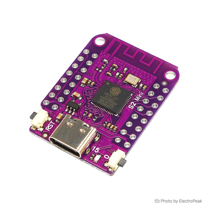
This board is a compact 3.3V ESP32-S2 development board for Wi‑Fi projects and native-USB work in a D1 mini-style footprint. It gives you 4M Bytes flash, 2M Bytes PSRAM, USB Type-C, and support for MicroPython, Arduino, CircuitPython, and ESP-IDF on a very small board.
The main buying filters are straightforward. This is a Wi‑Fi-only ESP32-S2 board with no Bluetooth or BLE support, and its USB behavior is not the same as a CH340-style USB-to-serial development board. If your project needs Bluetooth, more uncomplicated GPIO headroom, or a more familiar serial workflow, the ESP32-S3-WROOM-1 with 2MB PSRAM is the better fit.
Within the broader ESP32 family, this version makes the most sense for small IoT nodes, compact web-connected devices, and USB HID, MIDI, serial, or other USB-device experiments where native USB is a feature, not a surprise.
The board is built around the ESP32-S2FN4R2, an ESP32-S2-based MCU/SoC aimed at connected embedded work rather than general-purpose computing. The 240MHz clock speed is enough for sensor nodes, control panels, compact web interfaces, and many USB-device projects, but this is still a single-core ESP32-S2 board. That matters more in complex multitasking than in normal IoT firmware.
The memory combination is one of the main reasons to pick this board over a smaller-spec alternative. 4M Bytes flash gives you room for larger firmware, web assets, and updates. 2M Bytes PSRAM adds extra working memory that helps with buffering, larger displays, richer web interfaces, and Python-based projects.
| Specification | What it means in practice |
|---|---|
| Operating voltage: 3.3V | The GPIO logic level is 3.3V. Sensors, displays, and modules should be 3.3V-compatible unless you add proper level shifting. |
| Clock speed: 240MHz | Fast enough for typical Wi‑Fi firmware, local control, display driving, and USB applications, but not a reason by itself to expect unrestricted performance on every workload. |
| Flash: 4M Bytes | This gives more room for substantial firmware, OTA updates, file storage, and embedded web pages than very small-flash boards. |
| PSRAM: 2M Bytes | PSRAM is extra high-speed memory that helps when projects need larger buffers, Python runtimes, web content, or more demanding peripherals. |
| Digital I/O pins: 27 | The board exposes a healthy pin count for its size, but not all 27 are equally uncomplicated for general use because some board and chip functions take priority. |
| ADC, DAC, I2C, SPI, UART | It can handle common sensor, display, storage, and serial-peripheral tasks without needing extra interface chips for basic prototyping. |
| USB OTG | Native USB is a real advantage for USB-device projects, but practical host or device behavior still depends on firmware support and how the pins are used. |
| Size: 34.3*25.4mm | The board is genuinely compact and suited to tight layouts, though enclosure designs should allow for the reported length difference seen in some family documentation. |
If your project is already pressing against flash size or free-pin count, the ESP32-S3-WROOM-1 with 2MB PSRAM gives you 8MB SPI Flash and 45 programmable GPIOs. That can make system planning easier.
This board supports 2.4 GHz Wi‑Fi and does not support Bluetooth or BLE. That alone rules it out for many mixed-wireless projects such as BLE provisioning, beaconing, phone pairing, or low-power Bluetooth sensor roles.
The USB Type-C connector is useful, but it helps to be clear about what kind of USB board this is. The ESP32-S2 uses native USB, which is excellent for USB-device work, yet it can behave differently from a classic USB-to-UART board. If you plug it in expecting a CH340-style serial port every time, first setup can feel inconsistent until the correct firmware mode and board settings are in place.
USB Type-C handles both power and data on this board, and a USB-A to USB Type-C Data Power Cable is the right starting point for first power-up and programming. If you are new to ESP32 setup, the store guide on getting started with the ESP32 development board is a useful reference before you assume the hardware is faulty.
One more boundary matters here: USB programming and USB communication are documented, but onboard hardware debugging is not. Native USB can cover uploads, serial-style communication, and USB-device workflows, but that is not the same thing as having a dedicated hardware debug probe on the board.
If Bluetooth LE matters more than raw ESP32-S2 compatibility, choose the ESP32-C3 RISC-V board. For both Bluetooth and a more familiar CH340 serial workflow, the ESP-WROOM-32 with CH340 driver is the easier match.
LOLIN D1 mini shield compatibility is one of this board’s practical strengths, but read that as form-factor and ecosystem compatibility, not a blanket promise that every shield is drop-in safe. Physical alignment is only the first check.
The listed 27 digital I/O pins are also easy to overread. In real projects, some pins are tied up or made less convenient by USB functions, boot behavior, onboard LED use, and board-level chip connections such as flash or PSRAM-related constraints. That does not make the board difficult, but it does mean you should plan around the actual pinout instead of assuming every exposed pad is equally free.
Some V1.0.0-family boards have a known GPIO12/GPIO13 silkscreen confusion. It is not safe to trust those printed labels blindly on every batch, especially if your design depends on exact pin assignment. Check your board markings against a verified pinout before final wiring or shield stacking.
For loose prototyping, a Breadboard Jumper Wire Kit - 140 Pieces makes pin verification much easier than committing straight to soldered wiring or shield-only assumptions.
If your design needs more straightforward GPIO headroom with less pressure on pin planning, the ESP32-S3-WROOM-1 with 2MB PSRAM is the safer direction.
The board operates with 3.3V logic. Treat the GPIO as 3.3V-only and not 5V tolerant. A 5V sensor output, 5V UART adapter, or relay input connected directly to a GPIO can damage the board.
Power planning causes a lot of avoidable problems on small Wi‑Fi boards. Tiny logic-level peripherals are one thing; servos, motors, relay boards, LED strips, and other higher-current loads are another. Those should have their own suitable supply, with a common ground back to the board, rather than relying on the board’s 3.3V rail.
A separate external supply such as the Breadboard Power Supply Module - 3.3V/5V helps during prototyping because it keeps peripheral current draw off the board while you validate the firmware and wiring.
The other common false failure is the USB cable. A charge-only cable can power the board while giving you no USB communication at all, which makes the board look dead in the IDE even when nothing is wrong. Generic ESP32-WROOM tutorials can add to the confusion because the upload flow and USB behavior on an ESP32-S2 board are different.
If you want native USB capability but also prefer having onboard USB-to-UART available on the board, the ESP32-S2-WROOM with dual USB is a better match.
Arrival-day testing should be simple. Start with a known data-capable USB-A to USB Type-C Data Power Cable, select an ESP32-S2 or LOLIN S2 Mini-compatible target in your toolchain, and confirm that a USB or serial device appears before you begin deeper troubleshooting.
The board is compatible with MicroPython, Arduino, CircuitPython, and ESP-IDF. PlatformIO support is also available for the LOLIN S2 Mini family with board ID lolin_s2_mini. MicroPython is listed as the default firmware, though that should not be treated as batch-verified if your plan depends on preserving factory firmware.
For Arduino users, USB CDC On Boot may need to be enabled where relevant. A successful first test means the flash completes, the firmware runs, and USB behavior matches the selected firmware mode. With a Wi‑Fi scan example, you should see nearby networks detected.
Most first-time failures come from a charge-only cable, the wrong board target, missing USB CDC settings, expecting Bluetooth examples to work, or wiring according to an incorrect GPIO12/GPIO13 silkscreen on some V1.0.0-family boards. A small breadboard such as the 400 Points Half Size Breadboard - 5.5x8.5cm also makes first tests cleaner when you are checking pin assignments one signal at a time.
For a fuller setup path, see Installing the ESP32 Board in Arduino IDE (Windows, Mac OS X, Linux) and Getting Started with the ESP32 Development Board.
This board makes sense when the priority is small size, Wi‑Fi-only operation, native USB features, and D1 mini-style board geometry. It is not the default answer for every ESP32 project, and cross-shopping is more about wireless needs, USB behavior, and pin headroom than raw clock speed.
| Board | Best fit | Main reason to choose it | Trade-off to accept |
|---|---|---|---|
| This ESP32-S2FN4R2 S2 Mini | Compact Wi‑Fi projects and native-USB device work | Small format, USB Type-C, 4M Bytes flash, 2M Bytes PSRAM, D1 mini-style ecosystem | No Bluetooth and a less familiar USB workflow than CH340-style boards |
| ESP32-S2-WROOM with dual USB | Buyers who want ESP32-S2 plus onboard USB-to-UART and native USB | Dual USB approach reduces first-time friction for serial-style workflows | Still a single-core ESP32-S2 platform |
| ESP32-S3-WROOM-1 with 2MB PSRAM | Projects needing Bluetooth 5.0, more GPIO, and more flash | 45 programmable GPIOs, 8MB SPI Flash, Bluetooth 5.0, newer platform | Different board choice when your project no longer fits the S2 Mini’s compact brief |
| ESP-WROOM-32 with CH340 driver | General ESP32 prototyping with Bluetooth and classic USB-to-serial behavior | Familiar CH340 workflow and classic ESP32 feature set | May require CH340 driver installation |
| ESP32-C3 RISC-V board | Lower-cost BLE-focused work | Bluetooth 5 LE and Mesh support | 160MHz single-core RISC-V platform with different performance and feature priorities |
For straightforward legacy Wi‑Fi development, a different route is an ESP8266-style board such as the NodeMCU ESP8266 with CP2102 or NodeMCU ESP8266 V3 with CH340G. They are not direct substitutes for ESP32-S2 native-USB work, but they remain valid for simpler Wi‑Fi projects.
For a broader comparison of form factors and feature sets, see the ESP32 category.
No. It is an ESP32-S2 Wi‑Fi board, and ESP32-S2 does not support Bluetooth or BLE.
The usual causes are a charge-only cable, native USB firmware mode, or missing bootloader entry. Use a USB data cable, and if no port appears, hold BOOT, press and release RESET, then release BOOT; Arduino users may also need USB CDC On Boot enabled.
No. This board uses native USB on the ESP32-S2 rather than a CH340-style USB-to-UART bridge, so setup and serial behavior can be different.
Yes, in form factor and ecosystem terms, but not every shield should be assumed to be universally compatible. Check pin mapping, voltage, current demand, and physical clearance before treating a shield as drop-in.
No. The board provides 27 digital I/O pins, but some are less convenient for general use because of USB, boot, LED, and other board-level functions.
No. The operating voltage is 3.3V, and the GPIO should be treated as 3.3V logic.
Do not assume it can. High-current loads should use their own suitable power supply, with common ground shared to the board.
That is not clearly confirmed. The hardware matches the LOLIN S2 Mini family closely, but manufacturing origin is not explicitly confirmed.
The specified size is 34.3*25.4mm. A 33.4 × 25.4 mm figure appears in other family documentation, so enclosure-critical builds should confirm fit before committing.
It supports MicroPython, Arduino, CircuitPython, and ESP-IDF. PlatformIO support is also available for the LOLIN S2 Mini family.
| MCU/SoC | ESP32-S2FN4R2 |
|---|---|
| Product Family | ESP32 |
| Architecture | Tensilica Xtensa LX7 |
| CPU Cores | Single-core |
| Clock Speed (MHz) | 240MHz |
| Flash | 4MB |
| SRAM | 320 KB |
| External Memory | 2MB PSRAM |
| GPIO Pins | 27 |
| SPI interface Pins | 4 |
| I2C interface Pins | 2 |
| UART interface Pins | 2 |
| USB Ports | USB Type-C, USB OTG |
| CAN Bus Support | 1 (TWAI) |
| Ethernet Support | No |
| ADC Channels | 2 x 13-bit ADC (up to 20 channels) |
| DAC Channels | 2 x 8-bit DAC |
| PWM Channels | 8 |
| Operating Voltage (V) | 3.3V |
| GPIO Voltage (V) | 3.3V |
| Wireless | WiFi |
| Form Factor | 34.3 x 25.4 mm |
| IDE Support | MicroPython, Arduino, CircuitPython, ESP-IDF |
| Weight (g) | 2.4g |
| Antenna Type | Internal Antenna |
| Bluetooth Ver. | No |

Please complete your information below to login.
Sign In
Create New Account