
Overview
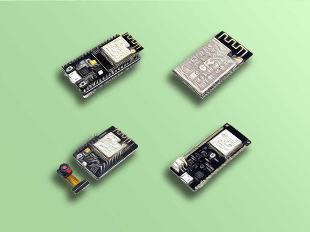
Today, there has been a growing interest in smart devices, automatic component control, and Internet of Things (IoT) applications in general. One of the key electrical components for IoT projects are ESP32 microcontroller-based modules. In this tutorial, we will teach you everything you need to know to get started with ESP32 boards.
What You Will Learn
- Getting familiar with different ESP32 based development boards
- Getting familiar with ESP32 various features and applications
- Getting to know different pins, interfaces and available sensors of ESP32
- Programming an ESP32 based development board with Arduino IDE
Why Should We Use ESP32?
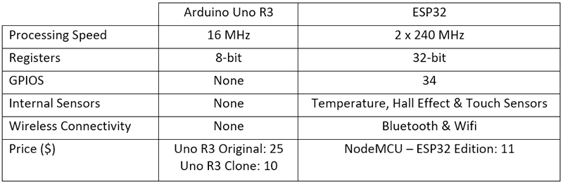
This is a question that answering to leads to full understanding of why this microcontroller is so precious and popular among all. A simple comparison between this microcontroller and a board like Arduino Uno, can properly answer this question. With processing speed about 10 times faster, 32-bit microcontroller while Arduino Uno is only 8-bit, 34 GPIO pins while Uno has none, having pins with the ability of being used as touch sensors, an internal temperature sensor, the capability of adding Wi-Fi and Bluetooth to your project, etc. are only a small part of the advantages of this microcontroller over Arduino Uno. And with all these advantages, it has a price so close to the price of an Arduino Uno board! So, let’s learn more about the features of this interesting microcontroller.
Different ESP32 Based Development Boards
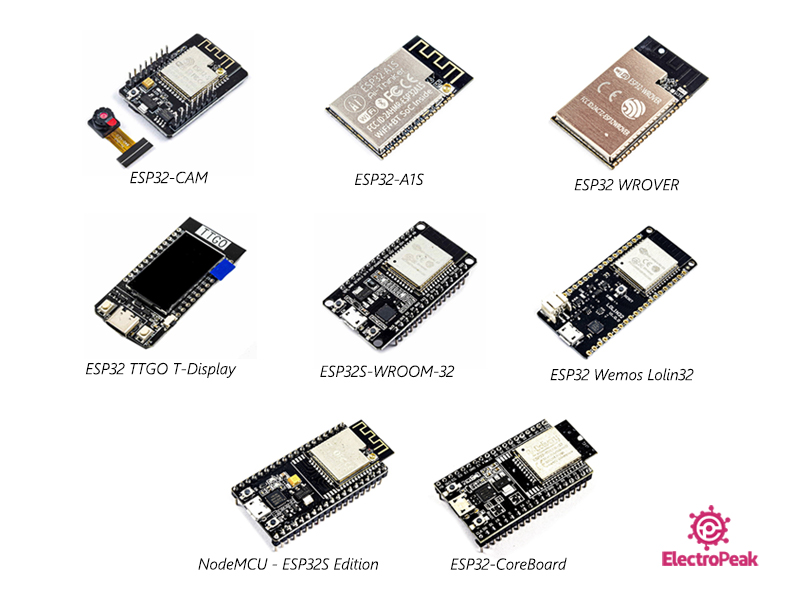
For easy use of ESP32 microcontrollers, several development boards have been available with the ESP32 microcontroller as the main chip. These boards include boards for both general and specific purposes. Examples of boards designed for a specific purpose are as following:
- ESP32-CAM Development Board
- ESP32-A1S Audio Development Kit
- TTGO T-Display ESP32 Development Board
And examples of boards designed for general purposes are as following:
- ESP32S Wemos Lolin32 Development Board
- ESP32-CoreBoard Development Board
- NodeMCU – ESP32S Edition
You can see the boards mentioned above and also some other ESP32 based boards in the image below.
Different Features and Specifications of ESP32
ESP32 microcontrollers, as mentioned before, have a lot of fascinating features, and we’ve been familiar with a number of them so far. In this section, we are going to look into its specifications more thoroughly.
Main Specifications
- Dual Core and the ability to control each core separately
- Processing speed up to 240 MHz
- Internal Wi-Fi with the capability of being set in 3 modes:
- STA (Station Mode): Connecting to a Wi-Fi station
- AP (Access Point): Functioning as a Wi-Fi network and other devices and connect to it
- STA_AP: Functioning as a Wi-Fi network and can still connect to other Wi-Fi stations
- Internal Bluetooth with 2 Versions:
- Classic BT (Classic Bluetooth)
- BLE (Bluetooth Low Energy)
Different Pins and Interfaces
- 34 programmable GPIO (General Purpose Input Output) pins
- 18 12-bit analog to digital pins (ADC)
- 2 8-bit digital to analog pins (DAC)
- 4 SPI interfaces
- 2 I2C interfaces
- 2 I2S interfaces
- 3 UART interfaces
- 16 PWM channels
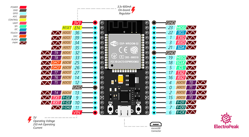
For more information on ESP32 pins, you can refer to the following link.
Full Guide to ESP32 Pinout Reference: What GPIO Pins Should We Use?
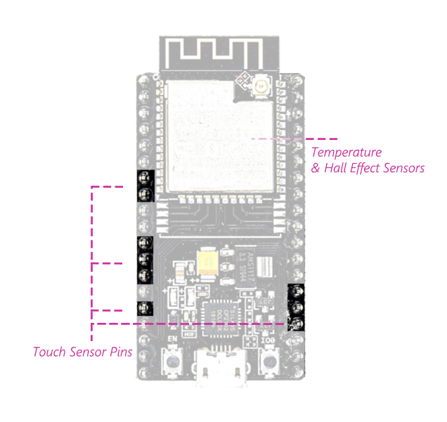
Available Sensors of ESP32
- 10 pins capable of being used as touch sensors
- Internal temperature sensor
- Internal hall effect sensor
To download the datasheet of ESP32, click here
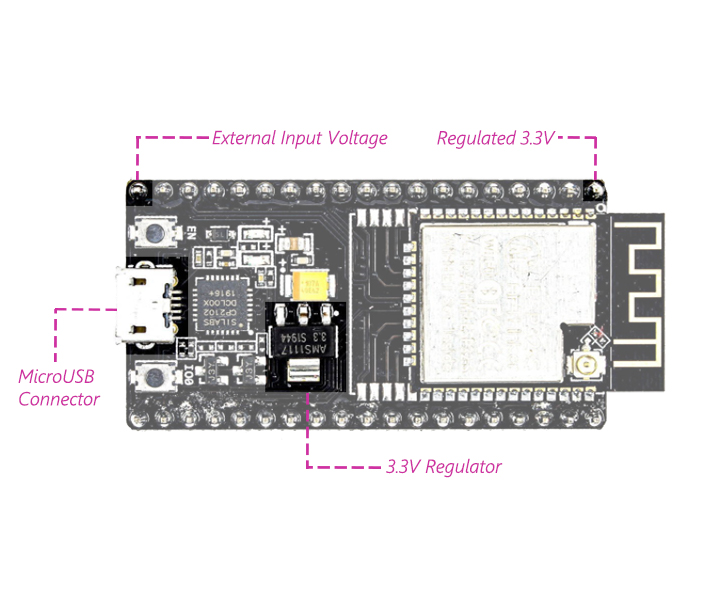
ESP32 Power Supply Options
These microcontrollers work on 3.3 voltage level. So, if you’re using the microcontroller itself –and not a development board- you need to provide a 3.3 voltage to power them. But the ESP32 based development boards have an on-board 3.3 voltage regulator. So if you’re using an ESP32 based development board -similar to boards introduced in the previous sections-, you can simultaneously power the board and also program the microcontroller using a micro USB port, which is available in almost all versions of development boards. These boards have a 3.3 voltage regulator which converts the 5V input supplied through the micro USB port to 3.3V needed by the microcontroller.
Install Drivers to Program ESP32 Boards
If you’re using the ESP32 itself and not a development board, you need a USB to TTL converter. In that case, you need to install the right drivers according to USB to TTL converter you use. But if you have an ESP32 based board, you won’t need a USB to TTL converter since they come with an on-board USB to TTL chip. In that case, you need to install the right driver based on the specifications of that development board. The converter used in development boards are mostly CP2102 or CH340.
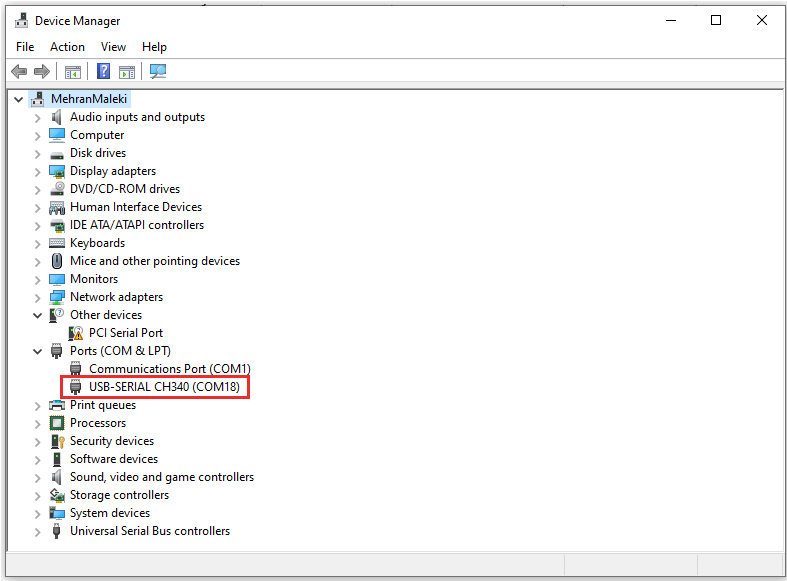
Anyway, if by any chance, you have no idea what converter is used on your board, you can do as following:
- Connect your board to the PC.
- In the “Start Menu”, search for “Device Manager”.
- After opening the “Device Manager”, you can see the name of the converter used on your board under the “Ports” section. If you see an exclamation sign inside a triangular located next to the name of the converter, it means that the driver is not installed on your computer.
For more details on how to install drivers, refer to the links below.
How to Install CH340 Driver on Windows
How to Install Drivers on Windows Manually
Programming Environments
One of the mains reasons why ESP32 is so popular is the simplicity in the way it can be programmed. The programming can be done in lots of different programming languages and environments. The most well-known of them are as follows:
- Arduino IDE
- LUA Programming Language
- MicroPython
- ESPressif IDF (IoT Development Framework)
- JavaScript
The First Project with ESP32: Control an LED
In this part, we are going to program an ESP32 based development board. For that, you need to have ESP32 boards installed on the Arduino IDE. In you haven’t installed ESP32 boards on the Arduino IDE yet, you can check the following links.
How to Install Arduino IDE on Windows & MAC
Installing the ESP32 Board in Arduino IDE (Windows, Mac OS X, Linux)
Hardware Components
Software Apps
The board we’re using here is NodeMCU – ESP32S Edition. This board has an on-board LED which is connected to the GPIO2 pin. We are going to control that LED by programming the board and make it blink. If you’re using a different ESP32 based development board, and you’re not sure if it comes with an on-board LED connected to the GPIO2 pin, you can easily connect an external LED to the GPIO2 pin. For that, you just need to connect one side of the LED to the GPIO2 pin and the other side to the GND. Then you can you same code.
Code
First, make sure that you have selected the right Board and Port.
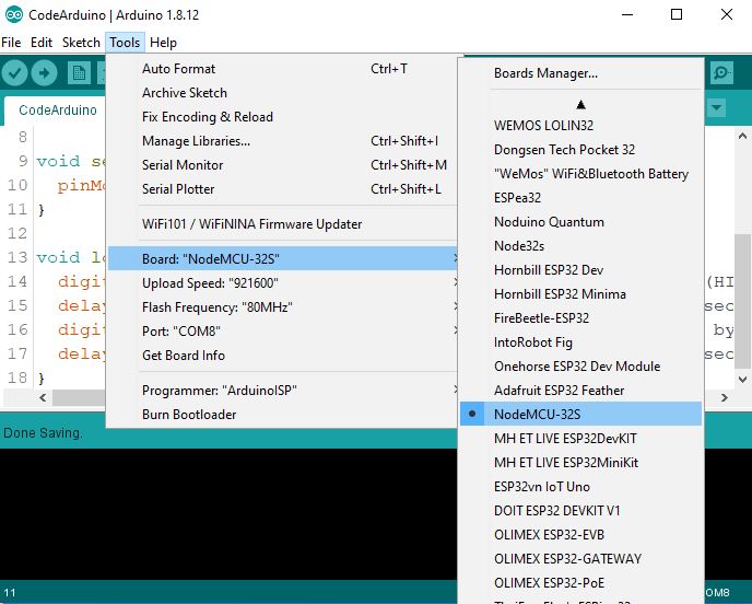
Then, upload the code below on your ESP32 Board.
/*
  Made on May 17, 2021
  By MehranMaleki @ Electropeak
  Home
*/
#define esp32_onboard_led 2


void setup() {
  pinMode(esp32_onboard_led, OUTPUT);
}

void loop() {
  digitalWrite(esp32_onboard_led, HIGH);   //turn the LED on (HIGH is the voltage level)
  delay(500);                              //wait for half a second
  digitalWrite(esp32_onboard_led, LOW);    //turn the LED off by making the voltage LOW
  delay(500);                              //wait for half a second
}
After successfully uploading the code on the Board, you can see an image like this in the Arduino IDE.
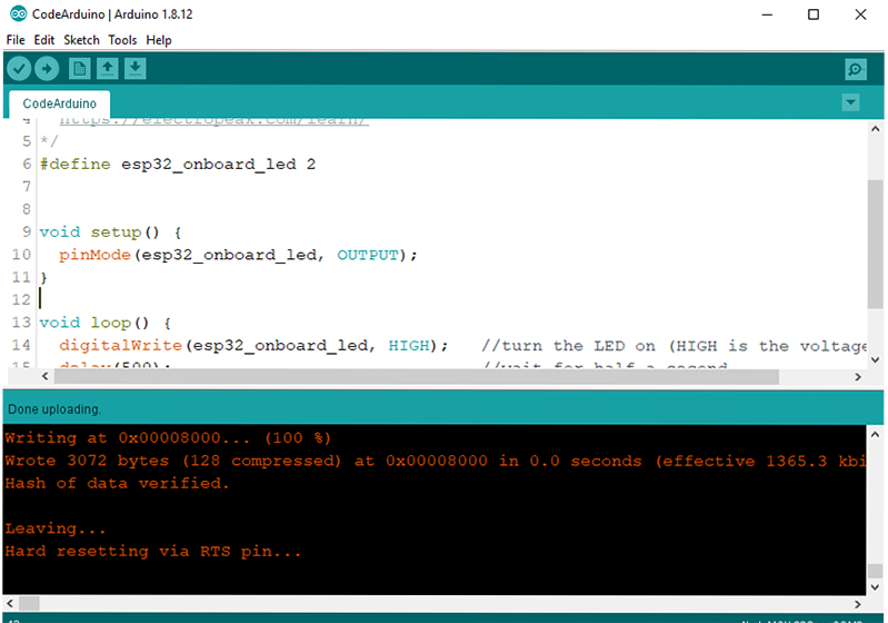
Then you can see the LED blinking.
What’s Next?
- Try to learn more details on ESP32 pins and the specification and features they have.
- Work with the internal temperature sensor of the ESP32 and display the temperature of its core.

Comments (2)
Hello, I’m going to combine ESP32CAM with HC-SR501 PIR motion sensor.
You can see my code here: https://shrib.com/#PocketGopher6ogvKyZ
I connected the Motion sensor output to pin number 12 or 13 directly
but I got blinking led without any motion detected?
where is the problem?
Hi,
Setting the pin 12 to INPUT is probably not a good idea! It might make the value of this pin too prone to noise. That’s why you see the LED blinking with no motion detected. Instead, you can set this pin to INPUT_PULLDOWN. In this way, the LED will only be turned on when motion is detected and it won’t be affected by noise or other disturbances.