
Product added to cart

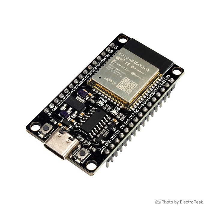
ESP-WROOM-32 ESP32 Development Board - CH340 Driver
$3.8000
In stock
SKU
COM-03-100
Volume discounts:
- +25 3 % $3.6700
- +100 5 % $3.6100
- +300 7 % $3.5500
- +500 8 % $3.4800
- +1000 10 % $3.4200
Ships in 2-3 business days, then:
Free delivery in 12-15 days by Tracked Economic Shipping on orders over $100.
Free delivery in 7-10 days by Express Shipping on orders over $300.
More shipping info

Shop with confidence Learn More
 ESP32-Cam-MB USB to TTL Programmer Shield Previous
ESP-WROOM-32 ESP32 Development Board specifications and setup limits
This board is sold as an ESP32S-DEV based on ESP-WROOM-32, with Wi‑Fi, Bluetooth, a CH340 USB-to-serial interface, USB Type-C, and 2x19 extension headers. At $3.95, it is a straightforward pick for low-cost ESP32 prototyping, test fixtures, and general Arduino IDE work when you want wireless features without spending much on the board itself.
The trade-off is documentation. It covers the essentials well enough across many ESP32 boards, but this is a generic board, and the board-level details many buyers care about most—exact pin behavior on the delivered revision, upload convenience, regulator margin, and low-power measurements—are not fully documented.
Want the same classic board class with a different USB bridge? Compare the ESP-WROOM-32 with CP2102 driver. For a broader setup walkthrough after purchase, keep the Getting Started with the ESP32 Development Board guide nearby.
Specifications of ESP-WROOM-32 ESP32 Development Board - CH340 Driver
- Microcontroller: ESP32-D0WDQ6 (dual-core) 32-bit
- CPU Frequency: Up to 240 MHz
- Flash Memory: 4 MB (32Mbit) SPI Flash
- ROM : 448 KB
- SRAM: 520 KB (16 KB SRAM in RTC)
- Wi-Fi: 802.11 b/g/n
- Bluetooth: Bluetooth 4.2 BR/EDR and BLE
- PCB Antenna:
- Digital I/O Pins: 38
- Analog Input Pins: 18
- Interfaces : UART, SPI, I2C, PWM, ADC, DAC
- USB-to-Serial Chip: CH340
- Operating Voltage: 3.3V
- USB Type-C connector:
- Powered via USB Type-C Connector, or via pin header:
- Reset and User/Firmware buttons:
- User and Power LED:
ESP32 38-pin header and GPIO limits
This board uses a 2x19 header layout, and that is the most useful way to read the “38-pin” description. It tells you the mechanical format and how many header positions you can wire to, not that your project gets 38 unrestricted GPIO.
Some header positions are power or ground, some ESP32 pins have fixed jobs, and some are only safe in certain roles. On the ESP32 classic family, GPIO6–11 are tied to the module flash and should not be treated like normal breakout pins. GPIO34–39 are input-only, so they can read switches and sensors but cannot drive relays, LEDs, or other outputs.
Boot-strapping pins need care as well. Pins such as GPIO0, GPIO2, GPIO5, GPIO12, and GPIO15 affect startup behavior, so a display, relay board, pull-up, or pull-down connected the wrong way can stop the board from booting or from entering programming mode.
This matters most on mixed I/O builds. A simple I2C sensor node is easy to place. A larger project with a TFT, relays, buttons, and analog inputs needs pin planning before you buy, especially if you intend to use Wi‑Fi at the same time.
For temporary wiring while you confirm which pins your firmware will actually use, a Breadboard Jumper Wire Kit - 140 Pieces is a practical bench accessory. If you want a refresher on common ESP32 pin conventions before wiring, keep the Getting Started with the ESP32 Development Board article open.
ESP32 CH340 driver, USB-C connection, and first upload
The board connects to your computer through the onboard CH340 USB-to-serial chip over USB Type-C. In other words, the USB-C port is the connector for serial programming, serial monitoring, and power delivery to the board—not native USB on the ESP32 itself.
First setup is straightforward in most cases. Use a known USB-C data cable, connect the board, and check whether a serial port appears on your computer. If no port appears, the two most common causes are a charge-only cable or missing CH340 support on the host OS.
On the software side, this board fits normal classic ESP32 workflows in Arduino IDE, ESP-IDF, and PlatformIO. In Arduino IDE, if there is no exact board entry for this OEM design, a generic ESP32 board profile such as ESP32 Dev Module is a practical starting point.
Upload behavior can vary on generic CH340 ESP32 boards. If an upload stalls at the “connecting” stage, that does not automatically mean the board is faulty. Some boards need a manual bootloader sequence: hold BOOT or User/Firmware, tap RESET or EN, then release BOOT when the upload starts.
Quick first-use check
- Connect the board with a known USB-C data cable.
- Check whether a serial port appears on the computer.
- Install the CH340 driver if the board is not recognized by the OS.
- Install the ESP32 board package in Arduino IDE, or use ESP-IDF.
- Select a generic ESP32 board profile if this exact OEM board is not listed.
- Select the correct serial port.
- Upload a simple blink or serial test.
- If upload stalls at connecting, hold BOOT/User-Firmware, tap RESET/EN, and release BOOT when upload starts.
- Open Serial Monitor and press reset to confirm boot output.
A simple first test is a minimal blink sketch or serial print example. A successful result is that the upload completes, the board appears as a serial device, and the sketch either toggles an onboard LED if your example maps to it or prints boot and runtime text in Serial Monitor after reset.
- A charge-only USB-C cable can prevent detection even when the board powers up.
- The wrong USB-serial driver will stop the board from appearing correctly.
- Selecting the wrong serial port can make a working board look dead.
- Choosing the wrong board profile can block uploads.
- USB-C here is only the connector type, so do not expect native USB behavior.
- Peripherals on strapping pins before the first upload can interfere with boot.
- Applying 5V logic directly to GPIO is not safe.
If you want the same board class but prefer a different USB bridge, compare the ESP-WROOM-32 with CP2102 driver. For setup help, see How to Install CH340 Driver on Windows and Installing the ESP32 Board in Arduino IDE (Windows, Mac OS X, Linux).
ESP32 ADC, strapping pins, and 3.3V logic limits
This is a 3.3V ESP32 platform. Treat the GPIO as 3.3V logic only, and do not connect 5V signals directly to the pins. USB power on the board does not make the GPIO 5V-tolerant.
The listed 18 analog inputs need a little interpretation before you commit to a sensor design. The ESP32 family exposes many ADC-capable pins, but they are not all equally convenient in real builds. ADC2 channels have limitations while Wi‑Fi is active, so a project that streams data over Wi‑Fi and reads multiple analog sensors at the same time may need careful pin choice or a different measurement approach.
Input-only pins also shape analog planning. GPIO34–39 can be useful for analog sensing because they are inputs, but they cannot double as outputs later if your design grows. Strapping pins add another layer: if an attached sensor board or relay module drives one of those pins at boot, the ESP32 may start in the wrong mode or fail to boot cleanly.
High-current loads are a separate issue. Motors, relays, solenoids, and large LED loads should use external driver hardware, and their own load power path as well. The board is there to provide logic control, not to source those loads directly.
If you want another listing in the same classic family and package style, the ESP-WROOM-32 Wi-Fi Bluetooth version is an equivalent option. For bench work, a Breadboard Power Supply Module - 3.3V/5V gives you a separate prototyping rail for sensors and support circuits while you test pin behavior.
To compare more boards in this family, the ESP32 category is the natural place to look at layouts and feature sets.
ESP32 power input and low-power caveats
The board can be powered through the USB Type-C connector or via a pin header. That tells you there is more than one power entry path, but it does not define the safe external header voltage range or which header pin you should use on every delivered revision.
Keep the 3.3V operating voltage of the ESP32 itself separate from the ways the board can be powered. The ESP32 logic domain is 3.3V, while the board may accept power through onboard conversion circuitry when fed through USB or the appropriate header input. Since the exact regulator part and input limits are not documented here, header-powered installations should be verified from the markings on the delivered board before wiring them into a larger system.
Do not assume the onboard power rail is meant to run motors, relays, or several hungry peripherals. Even when a project boots fine over USB, voltage dips from external loads can cause resets, unstable Wi‑Fi behavior, or intermittent upload problems.
Battery and deep-sleep work need extra caution. The ESP32 chip family supports low-power modes, but this board’s complete-board sleep current is not specified, and board-level details such as regulator quiescent current or LED draw are not documented. It can be used for low-power experiments, but if battery life is a design target, expect to measure the actual board current yourself.
For prototyping, a separate Breadboard Power Supply Module - 3.3V/5V is a sensible way to power add-on circuits instead of leaning on the board’s own rail for everything. If your project specifically needs an onboard 3.7V battery interface, the ESP32 with LiPo interface is the better-matched version.
For a broader setup overview, the Getting Started with the ESP32 Development Board guide covers the normal ESP32 bring-up flow.
ESP32 antenna, lifecycle, and board traceability
This board uses a PCB antenna. That is convenient for general-purpose builds because no external antenna is required, but antenna placement still matters. If you mount the board inside an enclosure, leave clearance near the antenna end and avoid pressing metal, batteries, or dense wiring directly against it.
The less obvious limitation is traceability. This is a generic/OEM board with no named manufacturer, no supplied schematic, and no documented revision history. For hobby and lab work, that is usually acceptable. For commercial hardware, service documentation, or repeatable long-term sourcing, it creates uncertainty around regulators, USB parts, button wiring, and pin labels across batches.
The ESP32-WROOM-32 family itself is well known and still very usable, so firmware support and examples are not the issue. The concern is that it is a mature classic ESP32 family, and for new long-life designs many buyers now prefer newer-family boards when they need clearer lifecycle direction, newer wireless features, or more memory headroom.
That makes this board a comfortable fit for prototyping, coursework, retrofitting existing ESP32-class code, and general wireless control projects. It is a less comfortable fit when you need traceable hardware identity, exact revision control, or a board you plan to standardize across many future builds without qualification testing.
If your enclosure or RF layout needs flexible antenna placement, the ESP32 WROOM-32U with USB-C is the right direction because it uses an external IPEX/IPX antenna connection instead of the onboard PCB antenna. You can also browse the wider ESP32 range if you need a different board style or feature set.
ESP32 classic alternatives: CP2102, LiPo, external antenna, and newer S3/C3 boards
This CH340 version is the low-cost, classic ESP32 option. If the core feature set is right and you are mainly deciding around workflow or project constraints, the better fit comes down to what your project actually needs rather than which board is “better” in general.
- ESP-WROOM-32 with CP2102 driver: pick this if you want the same classic ESP32 board class with a CP2102 USB bridge instead of CH340.
- ESP32 with LiPo interface: this is the right match when your project specifically needs an integrated 3.7V LiPo battery interface on the board.
- ESP32 WROOM-32U with USB-C: move this way if the project needs external antenna placement through an IPEX/IPX connector.
- ESP32-S3 with 2MB PSRAM: choose this when you need a newer ESP32 family with more memory headroom for larger firmware, richer interfaces, or heavier application code.
- ESP32-C3 RISC-V: a better fit if you want a newer compact ESP32-family board built around a RISC-V core for a different architecture and low-power-minded work.
Exact prices for those alternatives are not supplied here, so use this section as a fit check. For low-cost Wi‑Fi and Bluetooth prototyping, this board still makes sense. For battery integration, RF flexibility, or a newer-family starting point, one of the alternatives above will match the requirement more directly.
ESP32 development board FAQ and buying checklist
FAQ
Does this board need a CH340 driver?
Yes, it may. The board uses a CH340 USB-to-serial chip, and some operating systems already include support while others need the CH340 driver installed before the board appears as a serial port.
Is the USB-C port native USB?
No. On this board, USB-C is the physical connector used for CH340 serial communication and power, not native USB device functionality on the classic ESP32 chip family.
Does 38 pins mean 38 usable GPIOs?
No. It is a 38-pin layout, but some pins are power, ground, flash-connected, input-only, or boot-sensitive, so they are not all interchangeable general-purpose I/O.
Can I connect 5V sensors directly to the GPIO pins?
No. The GPIO should be treated as 3.3V logic, so 5V signals need level shifting or a divider before they reach the ESP32 pins.
Why do some ESP32 uploads need the BOOT button?
Because some generic ESP32 boards do not always handle auto-reset and bootloader entry reliably. If upload hangs at connecting, a manual BOOT and RESET sequence is a normal troubleshooting step rather than proof of a faulty board.
Are all 18 analog inputs equally usable?
No. The board exposes the ESP32 family’s analog capability, but practical use depends on pin role and on ADC2 limitations while Wi‑Fi is active.
Can I power it through the headers instead of USB-C?
Yes, header power is supported. The safe header pin and allowable voltage range are not specified here, so verify the markings on the delivered board before powering it that way.
Is this a good board for battery sleep-current projects?
Only if you are prepared to verify it yourself. Low-power operation is possible at the ESP32 family level, but this board’s complete-board sleep current is not specified.
Does it support CAN bus?
It can be used for ESP32 TWAI/CAN controller work, but you still need an external transceiver for physical CAN-style networking.
What should I choose instead if I need a better fit?
Choose the ESP-WROOM-32 with CP2102 driver for a different USB bridge, the ESP32 with LiPo interface for battery-connected builds, the ESP32 WROOM-32U with USB-C for external antenna placement, the ESP32-S3 with 2MB PSRAM for a newer higher-memory platform, or the ESP32-C3 RISC-V for a newer compact family.
What should I expect in the package?
Expect the board itself unless stated otherwise. No cable, headers, or printed setup materials should be assumed.
Accessories
Required
- USB-C data cable for programming and power.
- Computer or USB host for programming.
- CH340 driver when the operating system does not already provide it.
- ESP32 board package in Arduino IDE or an equivalent toolchain.
Recommended
- Breadboard Power Supply Module - 3.3V/5V for a separate prototyping rail for sensors and support circuits.
- 400 Points Half Size Breadboard - 5.5x8.5cm for quick sensor and display testing.
- Breadboard Jumper Wire Kit - 140 Pieces for temporary wiring and pin verification.
- 3.3V level shifting for 5V peripherals.
- External transistor, MOSFET, or relay driver for motors, relays, or inductive loads.
- External CAN/TWAI transceiver if the project needs CAN bus wiring.
Optional
- A USB cable tester or a known-good USB-C data cable to rule out charge-only cable problems.
- An external ADC for precision analog measurement.
- USB to Micro USB Cable - 30cm as a general bench cable for other boards and modules, though it is not used as the main connection for this board.
Compatibility summary
| Area | Summary |
|---|---|
| Computer connection | Connects through the onboard CH340 USB-to-serial interface over the USB Type-C connector. |
| Driver | CH340 driver may be needed depending on OS support. |
| Arduino IDE | Suitable; a generic ESP32 board profile is often used if the exact OEM board is not listed. |
| ESP-IDF | Suitable for ESP32 classic development. |
| PlatformIO | Suitable at family level, though an exact board identifier may not exist. |
| Wireless | Wi‑Fi 802.11 b/g/n and Bluetooth 4.2 BR/EDR + BLE. |
| Logic voltage | 3.3V logic; do not connect 5V directly to GPIO. |
| Power input | Power via USB Type-C connector or via pin header; safe header voltage and range are not supplied. |
| Analog use | 18 analog inputs are listed, but practical use has ADC2 and pin-role restrictions. |
| High-current loads | External drivers and usually separate load power are needed for motors, relays, and similar loads. |
| USB role | USB-C is used for CH340 serial programming and communication, not native USB on the ESP32 classic chip family. |
| CAN/TWAI | An external transceiver is required for physical CAN-style networking. |
| Antenna | Uses an onboard PCB antenna, so enclosure placement and clearance matter. |
Purchase decision summary
- Ideal for: Low-cost ESP32 Wi‑Fi/Bluetooth prototyping, Arduino IDE experiments, sensor, display, and control projects, and buyers who are comfortable working around generic-board documentation gaps.
- Maybe for: Small-batch embedded builds, enclosure prototypes, and battery experiments where you are willing to verify pinout, power path, and current draw on the delivered board.
- Consider another option if: You need native USB, guaranteed low-power board measurements, a published schematic, verified breadboard or mechanical details, traceable commercial hardware, or a newer ESP32 family for long-term new-design work.
Buying checklist
- ✓ Do you specifically want a classic ESP32 with Wi‑Fi plus Bluetooth 4.2 BR/EDR and BLE?
- ✓ Are you fine with a CH340 USB-to-serial workflow?
- ✓ Do you have a USB-C data cable, not just a charging cable?
- ✓ Do you understand that 38 pins does not mean 38 unrestricted GPIO?
- ✓ Do your sensors and modules use 3.3V logic, or do you have level shifting?
- ✓ Will your project avoid flash pins, input-only pins, and boot-strapping mistakes?
- ✓ If you need battery work, are you okay measuring actual board current yourself?
- ✓ If you need external antenna placement, would the WROOM-32U version suit better?
- ✓ If you need integrated LiPo support, would the LiPo-interface version suit better?
- ✓ If you need a newer ESP32 family, would the ESP32-S3 or ESP32-C3 be a better fit?
For software setup, the Installing the ESP32 Board in Arduino IDE (Windows, Mac OS X, Linux) guide covers the standard board-package workflow. If you want to compare within the same family before ordering, browse the wider ESP32 category.
| MCU/SoC | ESP32-WROOM-32 |
|---|---|
| Product Family | ESP32 |
| Architecture | Tensilica Xtensa LX6 |
| CPU Cores | Dual-core Xtensa LX6 |
| Clock Speed (MHz) | 240 MHz |
| Flash | 4 MB |
| SRAM | 520 KB |
| GPIO Pins | 36 |
| SPI interface Pins | 3 |
| I2C interface Pins | 2 |
| UART interface Pins | 3 |
| USB Ports | USB Type-C |
| CAN Bus Support | 1 (TWAI) |
| Ethernet Support | No |
| ADC Channels | 18 |
| DAC Channels | 2 |
| PWM Channels | 16 |
| Timers Count | 4 x 64-bit |
| Operating Voltage (V) | 3.3V |
| GPIO Voltage (V) | 3.3V |
| GPIO Current (mA) | 12mA |
| Sleep Current (µA) | 10µA (Deep Sleep) |
| Wireless | Bluetooth, WiFi |
| Form Factor | 51x28.5 mm |
| IDE Support | Arduino |
| Input Voltage (V) | 5V via USB |
| Antenna Type | Internal Antenna |
| Bluetooth Ver. | 4.2 |
Write Your Own Review

Please complete your information below to login.
Sign In
Create New Account