Product added to cart



No. There is no onboard USB, so you need an external USB-to-TTL serial adapter for normal programming.

Creating an account has many benefits: check out faster, keep more than one address, track orders and more.

We offer free shipping on all orders over $100and under 2kg.
Please note that free shipping is only available for orders under 2kg.
DHL is a renowned shipping courier known for its global reach and reliable delivery services. With a vast network and advanced logistics capabilities, DHL offers fast and secure shipping solutions for international shipments.
For the majority of countries, DHL provides an estimated delivery time of 5 to 7 days.
In certain instances, DHL may not be available for shipments to EU countries. In such cases, we may opt to ship your order using FedEx instead of DHL. Rest assured, FedEx offers a comparable estimated time of arrival (ETA) and your package should typically arrive within 5-7 days.
The base shipping cost for DHL is $35. You can see the final shipping amount on the checkout page. If your order is over $300and less than 2kg, you will qualify for free shipping through DHL Express.
Economy Shipping is a cost-effective international delivery option using a network of trusted logistics partners. Depending on the destination country, the carrier may vary to ensure the most efficient and reliable delivery.
Estimated delivery time is typically 10–15 business days in most cases; But may take up to 20 days. Orders over $100 and under 2kg qualify for free Economy Shipping.
All shipments include tracking. You will receive a tracking number along with a tracking link after dispatch. Most shipments can be tracked via 17TRACK.
Our shipping term is FOB Shenzhen, which does not cover any customs fees. It is important to note that you may be responsible for paying any charges imposed by your country's government, such as duties, taxes, and additional fees imposed by the courier company.
 Pro Mini BAITE ATMEGA328P-MU (Arduino Compatible) Previous
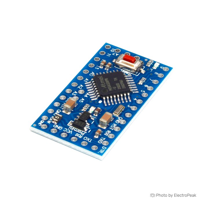
This Arduino Pro Mini 5V clone is a compact ATmega328p Arduino-compatible board built around the classic Pro Mini layout: 5 V logic, 16 MHz clock, and no onboard USB. It makes the most sense when you want a small controller you can wire into a project and leave there, instead of carrying a USB connector on the finished build.
The trade-off is setup convenience. You need an external USB-to-TTL adapter to program it, and first use is less forgiving than a board with built-in USB. If that suits your workflow, this board works well for many small 5 V sensor, control, timer, and embedded projects. If you want an easier starting point, the Arduino Nano (Clone) with FT232RL is the better fit because USB is already onboard.
It runs in the standard Arduino workflow, so classic ATmega328P sketches and libraries are the main reason to buy it. Across the Arduino Boards range, this is the one to pick when board size matters more than plug-and-play convenience. If you are still deciding between form factors, the Arduino Buying Guide is a useful companion.
Before ordering, plan to add a programmer such as the FT232RL FTDI 3.3V/5V Mini USB to TTL Serial Converter Adapter Module if you do not already have one.
The quick-reference sheet above is the full published spec set for this 5 V Pro Mini clone.
The core of this board is the ATmega328p, which is why it feels familiar if you have used an Uno, Nano, or other classic Arduino boards. The upside is broad sketch compatibility and a mature toolchain in Arduino IDE and PlatformIO. The limit is just as clear: this is still a small 8-bit AVR with modest memory by current standards.
Its 5 V operating voltage and 16 MHz clock suit many older Arduino examples, 5 V sensors, and modules that expect Uno-style logic levels. The same point cuts the other way. It is a poor match for projects built strictly around 3.3 V hardware unless you add level shifting where needed.
The pin count covers a lot of compact builds: 14 digital I/O, 6 PWM outputs, 1 UART, 1 SPI bus, 1 I2C bus, and 2 external interrupts. In practice, that handles the usual mix of buttons, status LEDs, displays, sensor modules, and small control tasks. Once you start stacking several communication peripherals with timing-sensitive outputs, the board’s compactness stops being the main constraint and I/O planning becomes the real issue.
The published analog input count is 6. Plan around that value, but do not assume a specific A6/A7 physical layout unless the PCB you receive clearly shows those pins. On Pro Mini-family boards, analog pin exposure can vary by layout, and if A6/A7 are present they are analog-only rather than normal digital I/O.
Memory is the other practical limit. With 32KB flash, 2 KB used by bootloader, 2 KB SRAM, and 1 KB EEPROM, this board handles classic Arduino control code comfortably, but it can run out of headroom with larger libraries, buffered serial traffic, menu-heavy displays, or feature-rich networking-style code. If you need more processing speed, higher-resolution analog input, or DAC output, move to the LGT8F328P Board with Type-C instead of stretching an ATmega328p past its comfortable range.
That is the appeal of the Pro Mini family for many buyers: a small board with the standard Arduino programming model, not a board trying to be more than that. If you are comparing it with other Arduino Boards, think of it as the compact embedded option rather than the easiest prototyping board.
This board has no onboard USB. To program it from a computer, you need a USB-to-TTL adapter and a few jumper wires. That is the main thing that separates the Pro Mini from easier boards such as the Nano.
Start with a 5 V-capable adapter. Suitable choices include the FT232RL FTDI 3.3V/5V Mini USB to TTL Serial Converter Adapter Module, CP2102 USB to TTL UART Serial Convertor Module, or CH340G USB to TTL Converter. For the wiring itself, add something like the Breadboard Jumper Wire Kit - 140 Pieces.
Wiring matters. Connect adapter TX to board RXI, adapter RX to board TX0, adapter VCC to board VCC, and GND to GND. The most common mistake is TX-to-TX and RX-to-RX instead of crossing them.
Reset handling is the next common stumbling block. If your adapter exposes DTR or RTS, setup is easier because auto-reset can work as intended. If auto-reset is not available, manual reset timing may be needed during upload, and a jumper from RESET to GND can be used to put the board in programming mode.
Once the hardware is connected, software support is straightforward. Use Arduino IDE or PlatformIO, install the adapter driver if your computer does not recognize it, then select the correct Pro Mini family board settings for a 5V/16MHz ATmega328P board. If you need the development environment first, see How to Install Arduino IDE on Windows & MAC.
| Step | What to do |
|---|---|
| 1 | Confirm the received board is the 5V/16MHz version. |
| 2 | Check whether headers are already installed; if not, solder headers or temporary wires. |
| 3 | Connect a 5V USB-to-TTL adapter: TX to RXI, RX to TX0, VCC to VCC, and GND to GND. |
| 4 | Connect DTR/RTS if available; otherwise be ready to use reset timing manually. |
| 5 | Install Arduino IDE or use PlatformIO. |
| 6 | Install the driver for the adapter if needed. |
| 7 | Select the correct board and processor settings for a 5V/16MHz ATmega328P Pro Mini family board. |
| 8 | Upload a simple Blink sketch to verify the programming path. |
A first successful upload should be simple: start with Blink or another minimal sketch and confirm the board behaves as programmed. If an onboard LED is available on the expected pin, it should blink after upload.
Most early upload failures come down to a short list: no adapter purchased, wrong adapter voltage, crossed serial lines wired incorrectly, wrong serial port, wrong board setting, missing driver, or reset timing issues. Errors like programmer is not responding or stk500_getsync often point to one of those basics rather than a dead board.
If you want a board that skips nearly all of this setup friction, choose the Arduino Nano (Clone) with FT232RL instead. It already has integrated USB.
Powering this board correctly comes down to using the right pin for the right supply. Use regulated 5 V on VCC. If you have a higher external supply or battery within the published limit, use RAW, not VCC.
The published board power input is 5 - 9 V MAX, and the circuit operating voltage is 5 V. Stick to that stated range rather than assuming a broader family range. The listing does not provide regulator details, so there is no reason to push the input side harder than necessary.
Higher voltage on RAW means the onboard regulation stage has to drop more voltage, which creates more heat. In compact installations, a regulated 5 V supply into VCC is often the cleaner approach if your system already provides it. If you are using an external adapter or battery, choose the input path carefully and tie grounds together properly.
The GPIO current specification also needs practical interpretation. The spec block lists 40 mA per I/O pin, but for normal design work 20 mA per pin is the safer target, and total current across pins should not exceed 200 mA. That matters because these pins are for logic and small loads, not for driving relays, motors, solenoids, or LED strips directly.
For those heavier loads, use external driver hardware. The board should provide the control signal while the driver stage handles the actual current.
If your project starts with 3.3 V peripherals or lower-voltage operation, the Arduino Pro Mini (Clone) - 3.3V / 8MHz is the cleaner fit than adapting a 5 V board down to everything else.
The published analog input count for this board is 6, which is enough for many small sensor projects. Even so, do not assume all Pro Mini-family boards expose every possible analog channel in the same physical way. If your design depends on a specific analog pin layout, inspect the actual PCB before committing it to a larger build.
A6 and A7 are the usual point of confusion. If those pins are present on the board layout, they are analog-only and not general digital I/O. That can affect plans for mixed analog-and-digital sensor wiring on a tight footprint.
Mechanical compatibility catches buyers too. This board is Arduino-compatible in the software sense, but it does not usually fit standard Uno-style shields directly. The Pro Mini form factor favors direct wiring, custom headers, and embedded installation instead of stacking plug-on expansion boards.
That wiring-first approach can be an advantage in permanent builds because it saves space and removes an unnecessary USB connector. During prototyping, it is less convenient, especially if headers are not preinstalled. A small prototyping surface such as the 400 Points Half Size Breadboard - 5.5x8.5cm helps with initial testing before the board is soldered into place.
For wearable integration rather than compact conventional wiring, the LilyPad Arduino 328 (Clone) is the better match because its sewable pad layout is built for fabric projects instead of pin headers and jumper leads.
The right alternative depends on the problem you are trying to solve. This board is the compact, classic ATmega328P option for 5 V projects when you are comfortable with external programming hardware. Change that assumption, and another board can make more sense.
Need the same general Pro Mini approach from another source? The BAITE Pro Mini (ATmega328P-MU) is an equivalent option in the same family. It is still a Pro Mini-style board, still needs an external USB-to-TTL converter, and is best treated as an alternate sourcing choice rather than an upgrade or downgrade.
Programming convenience is the usual reason to step away from this board. In that case, pick the Arduino Nano (Clone) with FT232RL. It keeps the familiar ATmega328P/16 MHz Arduino workflow and adds integrated USB with a breadboard-friendly layout, which makes early prototyping easier.
For 3.3 V sensors, lower-voltage logic, or lower-speed operation, the Arduino Pro Mini (Clone) - 3.3V / 8MHz is the better fit. It serves the same compact Pro Mini role, just in a voltage and clock range that suits 3.3 V projects better.
If the standard ATmega328P is the limiting factor, the LGT8F328P Board with Type-C is the need-based step up. It adds features such as higher-resolution ADC, DAC, and higher clock options, but the trade-off is a non-standard MCU that may need specific board support.
Some projects need USB as part of the job, not just for setup. For those, the Arduino Pro Micro (Clone) with ATmega32U4 is the more appropriate direction. Its native USB support fits HID-style devices and USB-connected tools, but it is a different board family with a different MCU and pinout.
There is also the broader original-versus-clone question. A branded SparkFun-style 5V/16MHz Pro Mini is the provenance-and-support reference point for this family, while a clone like this one is the lower-cost route. On this specific board, exact regulator details, revision, bootloader, and manufacturer are not supplied, so buyers who need fixed traceability should weigh that carefully.
If you are comparing compact boards across the lineup, the Arduino Buying Guide helps frame those trade-offs without assuming one form factor is right for every project.
No. There is no onboard USB, so you need an external USB-to-TTL serial adapter for normal programming.
A 5V-capable FT232RL, CP2102, or CH340-based adapter can be used. Matching the logic voltage correctly and having DTR or RTS available makes setup easier.
Yes. Use regulated 5V on VCC and connect ground correctly.
Yes, within the published limit, but feed higher input voltage through RAW rather than VCC. The listed board power supply range is 5 - 9 V MAX.
The published specification is 6 analog input pins. If your design depends on specific extra analog pins being physically exposed, check the actual PCB layout first.
No. If A6 and A7 are present on the layout, they are analog-only rather than normal digital I/O.
Yes. Arduino IDE and PlatformIO are the intended development environments, though correct board and upload settings still matter.
Those errors are usually caused by wiring or setup issues rather than the board itself. Check adapter voltage, TX/RX crossover, serial port, board selection, driver installation, DTR/reset timing, and possible bootloader-related variation.
Usually not directly. Most standard shields are not mechanically compatible with the Pro Mini form factor.
No, not as a normal workflow choice. This board is meant for Arduino IDE or PlatformIO, and if Python on the microcontroller is the priority, Raspberry Pi Pico or ESP32/ESP8266-class boards are the better direction.
That is not clearly specified. Plan for the possibility that headers are not preinstalled.
| MCU/SoC | ATmega328 |
|---|---|
| Product Family | Arduino |
| Architecture | AVR |
| CPU Cores | 1 |
| Clock Speed (MHz) | 16 MHz |
| Flash | 32 KB |
| SRAM | 2KB |
| EEPROM | 1 KB |
| GPIO Pins | 14 |
| SPI interface Pins | 1 |
| I2C interface Pins | 1 |
| UART interface Pins | 1 |
| Ethernet Support | No |
| ADC Channels | 6 |
| PWM Channels | 6 |
| Operating Voltage (V) | 5V |
| GPIO Voltage (V) | 5V |
| GPIO Current (mA) | 40 mA |
| Wireless | No |
| Input Voltage (V) | 5~9V |
| Antenna Type | No |
| Bluetooth Ver. | No |

Please complete your information below to login.
Sign In
Create New Account