
Product added to cart

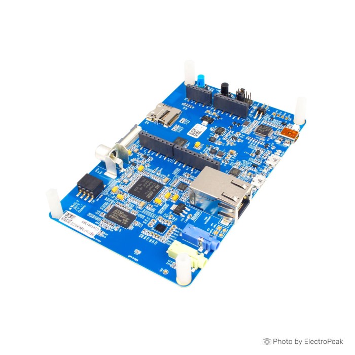
STM32F746G Discovery Board
$95.9500
In stock
SKU
MIC-02-010
Volume discounts:
- +5 3 % $92.9700
- +10 5 % $91.4800
- +25 6 % $89.9800
- +50 8 % $88.4900
- +100 9 % $87.0000
Product Variations:


Add an Accessory:


Ships in 2-3 business days, then:
Free delivery in 12-15 days by Tracked Economic Shipping on orders over $100.
Free delivery in 7-10 days by Express Shipping on orders over $300.
More shipping info

Shop with confidence Learn More
 STM32F103C8T6 Blue Pill ARM Development Board Previous
STM32F746G Discovery Board review
The STM32F746G Discovery Board is an STM32F7 development platform built around the STM32F746NGH6 ARM Cortex-M7 microcontroller. Its integrated 4.3-inch capacitive touchscreen, audio hardware, Ethernet, dual USB OTG, external memory, camera connector, microSD connector, Arduino Uno V3 headers, and on-board ST-LINK/V2-1 support peripheral-rich embedded evaluation and prototypes.
This is not a minimal GPIO learning board. It is for developers evaluating display, audio, storage, networking, and expansion hardware together who understand the limits of 3.3 V I/O, 64 Mbit available SDRAM, and USB power capacity. For other form factors and MCU families, browse other STM32 development boards.
Specifications of STM32F746G Discovery Board
- Microcontroller: STM32F746NGH6
- Flash memory: 1 Mb
- RAM: 340 Kb
- Power supply via USB
- External power supply: 5 V
- External power supply: 3-5 V DC
- USB functions: virtual COM port
- USB functions: mass storage
- USB functions: debug port
- Display: 4.3-inch
- Display resolution: 480x272
- Display type: color LCD-TFT
- Display touch type: capacitive touch screen
- SDRAM: 128 Mbit
- SDRAM available: 64 Mbit
- USB OTG HS with Micro-AB connectors
- USB OTG FS with Micro-AB connectors
- Ethernet connector compliant with IEEE-802.3-2002
- Five power supply options
- ST LINK/V2-1
- USB FS connector
- USB HS connector
- VIN from Arduino connector
- External 5 V from connector
- Power supply output: 3.3 V
- Power supply output: 5 V
- Arduino Uno V3 connectors
STM32F746G Discovery Board specifications explained
The STM32F746NGH6 is the processing foundation of this STM32F7 Discovery board. It suits embedded applications combining user interfaces, data movement, audio, networking, and peripheral control rather than a single simple GPIO task.
| Area | What it means in a project |
|---|---|
| Internal Flash and RAM | The on-chip program memory and working memory hold firmware, variables, stacks, and time-critical code. They form the application foundation before external memory is used. |
| External SDRAM | The board has 128 Mbit SDRAM installed, but 64 Mbit is available to the board. That equals 8 MB accessible through its 16-bit data-bus arrangement. This space is useful for display framebuffers, decoded images, GUI buffers, and larger runtime data. |
| Quad-SPI Flash | The 128-Mbit Quad-SPI Flash memory stores assets and data that do not need to remain in internal Flash, such as graphics, fonts, audio samples, or application resources. |
| 4.3-inch LCD-TFT | The 480x272 color display provides a practical on-board target for embedded GUI work. Capacitive touch enables direct interaction without adding a separate display module, touch controller, and wiring harness. |
Memory planning matters here. Projects requiring more than 8 MB of SDRAM should not assume the installed 128 Mbit device is fully accessible.
For a different display-platform and MCU-family balance, the STM32F429I Discovery Board with LCD combines an STM32F429ZIT6, 2 MB Flash, a 2.4-inch QVGA TFT LCD, and 64 Mbits of external SDRAM. It is a need-based alternative, not a direct upgrade path.
STM32F746G touchscreen, audio and connectivity features
The integrated 4.3-inch capacitive touch LCD is the central reason to choose this board for GUI and HMI evaluation. You can develop display layouts, touch handling, graphics buffering, and interface logic on the target hardware rather than assembling a separate display stack first.
Audio development is well covered. The board includes an SAI audio codec, line input and line output, stereo speaker outputs, two ST MEMS microphones, and an SPDIF RCA input connector. These interfaces support audio playback, recording, microphone tests, and digital-audio experiments without a separate codec board.
For communication and storage work, it provides Ethernet, USB OTG HS, USB OTG FS, a microSD card connector, an RF-EEPROM connector, pushbuttons, and four LEDs. The USB OTG connectors use Micro-AB connections; a USB to Micro USB Cable - 30cm suits those USB OTG connections, but it is not the cable required for the ST-LINK programming connection.
A camera connector is present, but no camera module is included. Camera-to-display projects require a separately selected compatible camera module. Directly supported use cases include touchscreen GUI demonstrations, audio experiments, DCMI camera-to-display projects, and STM32F7 educational labs covering USB OTG, Ethernet, external memory, audio, and display peripherals.
For projects focused on high-performance audio and motion-sensing evaluation rather than an integrated touchscreen platform, choose the STM32F407 Discovery Board, which includes a CS43L22 audio DAC, digital microphone, and LIS302DL 3-axis accelerometer.
STM32F746G setup, power and ST-LINK compatibility
ST-LINK/V2-1 is built into the board, so normal programming and debugging do not require an external debugger. On Windows, install the ST-LINK/V2-1 driver before the first connection; without it, the board can appear as an unknown USB device.
The board supports several power arrangements. USB power is supported, but the USB host must provide the documented 500 mA requirement during enumeration. Use an external 5 V supply when the LCD, attached peripherals, or external circuits make USB-only power unsuitable.
Do not treat the stated 3-5 V DC external-power wording as a general wiring instruction. Use the documented 5 V external-power arrangement and check the board documentation before selecting a power input for a custom setup.
First connection checklist
- Install the ST-LINK/V2-1 driver before first use on Windows.
- Select the intended board power source before applying power.
- Connect the board through the ST-LINK/V2-1 USB connection for programming and debugging.
- Confirm that the USB host can provide the required 500 mA if USB power is used.
- Install STM32CubeF7 and current BSP support, or configure STM32CubeIDE, Keil MDK, IAR EWARM, or a GCC-based toolchain.
- Load an LCD, audio, Ethernet, or peripheral example and confirm successful programming and observable board behavior.
A successful first test shows an ST-LINK connection, a completed firmware download, and visible LCD output or another expected peripheral response. If programming fails, check the Windows driver first. If the board does not start reliably from USB, use a host that can meet the current requirement or move to external 5 V power. QSPI errors can indicate outdated BSP support on boards with revision-dependent flash devices.
What you need to get started
- Required: A data-capable Mini-B cable for the ST-LINK connection is needed for normal first-time programming and debugging. No matching cable is supplied here.
- Required on Windows: The ST-LINK/V2-1 driver.
- Required: STM32CubeIDE, STM32CubeF7/BSP support, or another compatible STM32 toolchain.
- Recommended: External 5 V power for higher-load setups where USB-only power is insufficient.
STM32F746G Arduino shield and camera compatibility
Arduino Uno V3 connectors provide physical expansion compatibility, but they do not make every Arduino shield electrically safe. STM32 I/O uses 3.3 V logic, so a 5 V shield must be checked for voltage compatibility or used with suitable level shifting before connection.
Board revisions can have slight differences in Arduino header functions. Check projects that depend on particular header pins against the schematic for the actual board revision rather than relying on a generic Arduino-header assumption.
The camera connector requires a DCMI-compatible module with the appropriate 30-pin ZIF arrangement. STM32F4DIS-CAM and OV9655-based modules are compatible examples, but arbitrary camera modules should not be expected to work. A camera module is a separate requirement.
External prototyping accessories
- Recommended: A 400 Points Half Size Breadboard - 5.5x8.5cm provides a practical area for 3.3 V external circuits.
- Recommended: The Breadboard Jumper Wire Kit - 140 Pieces helps connect compatible breakouts and prototype circuits to the board.
- Required for 5 V shield signals: Use 3.3 V-compatible shields or an appropriate level-shifting plan. No matching level-shifter product is supplied here.
For motion sensing or magnetic-field projects, the STM32F3 Discovery Board is the right fit when its gyroscope, accelerometer, and magnetic sensor set is the main requirement.
STM32F746G Discovery Board limitations and revision notes
Installed SDRAM capacity is not the same as usable SDRAM capacity. Only 64 Mbit, or 8 MB, is accessible, so applications requiring more external RAM should not rely on this board alone.
USB-only power depends on a host capable of meeting the documented 500 mA requirement. Heavier peripheral loads need external 5 V power. The Arduino headers also require caution: direct connection of 5 V shield signals is unsafe for the board’s 3.3 V STM32 I/O.
Some units have reported intermittent touchscreen behavior, especially at low temperatures. This is not established as affecting every unit, but it matters for HMI work requiring dependable touch operation across a wide temperature range.
QSPI flash devices can vary by board revision. Current BSP support is needed for rev C-03 boards fitted with W25Q128J flash, while earlier documented revisions use N25Q128A devices. Arduino header mapping also differs slightly between documented revisions, so verify revision-specific schematics when a project depends on exact pin functions.
The board exposes fewer MCU pins than an EVAL board. This matters for highly custom peripheral designs where broad pin access takes priority over integrated display, audio, and connectivity hardware.
STM32F746G Discovery Board alternatives: F429I, F407, F3 and Blue Pill
The right STM32 development board depends on the peripherals and form factor a project needs. The STM32F746G Discovery Board targets integrated GUI, audio, networking, USB, camera, and external-memory evaluation; the boards below serve narrower or different development priorities.
| Board | Supplied specifications | Use case |
|---|---|---|
| STM32F746G Discovery Board | STM32F746NGH6, 1 Mb Flash, 340 Kb RAM, 4.3-inch 480x272 capacitive LCD-TFT, 64 Mbit available SDRAM | Touchscreen, audio, Ethernet, USB OTG, camera, storage, and peripheral-rich STM32F7 evaluation |
| STM32F429I Discovery Board with LCD | STM32F429ZIT6, 2 MB Flash, 2.4-inch QVGA TFT LCD, 64 Mbits external SDRAM | Display and external-memory application development on the STM32F4 family |
| STM32F407 Discovery Board | CS43L22 audio DAC with integrated speaker driver, digital microphone, LIS302DL 3-axis accelerometer, 1 MB Flash | High-performance audio and motion-sensing evaluation |
| STM32F3 Discovery Board | L3GD20 3-axis digital gyroscope, LSM303DLHC magnetic and acceleration sensors, 256 KB Flash, 48 KB RAM | Motion sensing and magnetic-field applications |
| STM32F103C8T6 Blue Pill Board | 53 x 22 mm form factor, 72 MHz Cortex-M3, 64 KB Flash, 20 KB SRAM | Compact robotics, control projects, and compact embedded systems |
For a different MCU ecosystem rather than a direct STM32 substitute, the NXP LPC845 MCU Board offers an NXP Cortex-M0+ prototyping approach.
Frequently asked questions
Does the STM32F746G Discovery Board need an external programmer?
No. The board includes on-board ST-LINK/V2-1 programming and debugging support, so an external debugger is not required for normal use.
Do I need to install a driver for STM32F746G Discovery Board ST-LINK on Windows?
Yes. Windows users need the ST-LINK/V2-1 driver before first use; without it, the board can appear as an unknown USB device.
Can the STM32F746G Discovery Board run from USB power only?
Yes, provided the USB host can meet the documented 500 mA requirement. Use external 5 V power for heavier loads or when the USB host cannot provide sufficient current.
Are Arduino shields compatible with the STM32F746G Discovery Board?
They are physically compatible with the Arduino Uno V3 connectors, but 5 V shields are not automatically electrically compatible. STM32 I/O is 3.3 V, so check signal levels or use level shifting before connection.
Why does the STM32F746G Discovery Board list 128 Mbit SDRAM but only 64 Mbit available?
The board makes 64 Mbit, or 8 MB, accessible through its 16-bit SDRAM data-bus arrangement. Plan GUI buffers and runtime memory around the available capacity rather than the installed device capacity.
Which camera module works with the STM32F746G Discovery Board?
Use a DCMI-compatible camera module with the appropriate 30-pin ZIF arrangement. STM32F4DIS-CAM and OV9655-based modules are compatible examples; a camera module is not included.
Does the STM32F746G Discovery Board touchscreen have known issues?
Some units have reported intermittent or low-temperature touchscreen behavior. This does not establish a fault on every board, but temperature-sensitive HMI projects should include their own touch validation.
What is the STM32F746G Discovery Board alternative for motion sensing or a compact control project?
The STM32F3 Discovery Board is intended for motion sensing and magnetic-field applications. The STM32F103C8T6 Blue Pill Board is intended for compact robotics, control projects, and compact embedded systems.
Purchase decision summary
- Ideal for: STM32F7 developers building touchscreen GUI, audio, Ethernet, USB OTG, camera, storage, or peripheral-rich evaluation prototypes on the STM32F746NGH6 platform.
- Maybe for: Students and makers who already understand embedded C, STM32 tools, 3.3 V logic, external memory setup, and the trade-offs of a full-featured Discovery board.
- Consider another option if: You need direct 5 V Arduino shield compatibility, more than 64 Mbit of usable SDRAM, a minimal beginner board, dependable low-temperature touchscreen behavior without additional validation, or USB-only operation with substantial peripheral current demand.
Buying checklist
- ✓ My project benefits from an integrated 4.3-inch, 480x272 capacitive LCD-TFT.
- ✓ I need the STM32F746NGH6 / STM32F7 platform rather than a basic compact STM32 board.
- ✓ I understand that the board has 64 Mbit of available SDRAM, not the full 128 Mbit installed capacity.
- ✓ I can use 3.3 V-compatible shields and peripherals, or I have an appropriate level-shifting plan.
- ✓ I have a suitable programming cable for the ST-LINK connection; no matching Mini-B cable is supplied here.
- ✓ I can provide external 5 V power if USB power is insufficient for my load.
- ✓ I will install the ST-LINK/V2-1 driver before first Windows use.
- ✓ My camera plan uses a DCMI-compatible 30-pin ZIF module, not a generic camera module.
- ✓ I can use the latest BSP and check board revision if QSPI flash or Arduino header mapping matters.
- ✓ I do not require guaranteed touchscreen behavior in low-temperature conditions without additional validation.
| MCU/SoC | STM32F746NGH6 |
|---|---|
| Product Family | STM32 Discovery |
| Architecture | ARM Cortex-M7 |
| CPU Cores | 1 |
| Clock Speed (MHz) | 216 MHz |
| Flash | 1 MB |
| SRAM | 320 KB |
| EEPROM | 64-Kbit RF-EEPROM (M24SR64-Y) |
| External Memory | 128-Mbit Quad-SPI Flash, 128-Mbit SDRAM |
| SPI interface Pins | 6 |
| I2C interface Pins | 4 |
| UART interface Pins | 4 |
| USB Ports | USB HS OTG, USB FS OTG |
| CAN Bus Support | 2 |
| Ethernet Support | Yes |
| ADC Channels | 3 |
| DAC Channels | 2 |
| Timers Count | 18 |
| Operating Voltage (V) | 5V |
| GPIO Voltage (V) | 3.3V |
| Wireless | No |
| Form Factor | Discovery Board |
| IDE Support | SWD |
| Input Voltage (V) | 3-5V DC |
| Antenna Type | No |
| Bluetooth Ver. | No |
Write Your Own Review

Please complete your information below to login.
Sign In
Create New Account