
Product added to cart

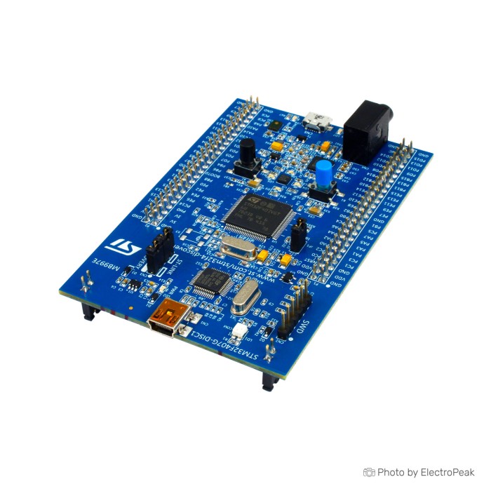
STM32F407 Discovery Board
$38.2500
In stock
SKU
MIC-02-006
Volume discounts:
- +10 4 % $36.7800
- +25 6 % $36.0500
- +50 8 % $35.3100
- +100 10 % $34.5800
- +300 12 % $33.8400
Product Variations:


Add an Accessory:


Ships in 2-3 business days, then:
Free delivery in 12-15 days by Tracked Economic Shipping on orders over $100.
Free delivery in 7-10 days by Express Shipping on orders over $300.
More shipping info

Shop with confidence Learn More

STM32F407 Discovery Board review
The STM32F407 Discovery Board is an STM32F4 educational development board with embedded ST-LINK/V2-A debugging, onboard motion sensing, digital microphone and audio hardware, LEDs, push buttons, USB OTG FS, and accessible I/O headers. It suits feature-rich STM32 learning, peripheral experiments, and early prototypes without separate sensor or debugger modules.
The main trade-offs matter before ordering: direct MCU serial requires extra wiring, the 3 V and 5 V output pins are not intended for high-current loads, and onboard audio cannot share SDIO storage directly without a workaround. For developers comparing STM32 development boards, this board is built for hands-on STM32F4 exploration rather than a compact minimum-system design.
Specifications of STM32F407 Discovery Board
- Supply voltage through USB bus
- External 5 V supply voltage
- 1 MB Flash
- 192 KB RAM
- LED1 red/green for USB communication
- LED2 red for 3.3 V power on
- LD3 orange user LED
- LD4 green user LED
- LD5 red user LED
- LD6 blue user LED
- LD7 green USB OTG LED for VBus
- LD8 red USB OTG LED for over-current
- LQFP100 package
- External application power supply: 3 V
- External application power supply: 5 V
- LIS3DSH ST MEMS 3-axis accelerometer
- MP45DT02 ST MEMS audio sensor
- Omni-directional digital microphone
- CS43L22 audio DAC
- Integrated class D speaker driver
- Virtual com port
- Mass storage
- Debug port
STM32F407 Discovery Board specifications explained
The STM32F407 platform combines a 32-bit ARM Cortex-M4F core with 1 MB Flash and 192 KB RAM. That memory supports STM32CubeF4 firmware, HAL or LL drivers, multiple peripheral stacks, audio buffers, and moderately complex embedded applications without immediately reaching the limits of a small minimum-system board.
| Board feature | Why it matters |
|---|---|
| Embedded ST-LINK/V2-A debug tool | The onboard debugger handles programming and debugging through the Mini-B connection, so normal development does not require a separate programmer. |
| Extension headers | Two documented 2×25 headers on 2.54 mm pitch expose microcontroller I/O for sensors, displays, buses, and custom prototype wiring. |
| LEDs and push buttons | The user LEDs and buttons provide immediate targets for GPIO, interrupts, timers, and basic debugging exercises without external parts. |
| Accelerometer | The onboard 3-axis motion sensor supports tilt, gesture, and motion-triggered exercises, though the matching driver depends on PCB revision. |
| Digital microphone and CS43L22 audio DAC | The audio hardware supports playback, recording, and signal-processing experiments, but storage design needs care because audio and SDIO share pins. |
| USB OTG FS | The Micro-AB connector supports USB device and host experiments, including keyboard, mouse, and storage exploration. |
| 3 V and 5 V application power | These rails can support small external circuits, but their output pins are limited to 100 mA. Motors, Wi-Fi modules, and other larger loads need their own regulated supply. |
This is a feature-dense board, not a compact, breadboard-first minimum system. For prototypes using the extension headers, a 400 Points Half Size Breadboard - 5.5x8.5cm provides a practical place to connect external circuits.
For a compact, breadboard-friendly STM32 minimum system, the STM32F103C8T6 Blue Pill fits its 53 × 22 mm form factor and 64KB Flash. It takes a different design approach: smaller and simpler, without this board’s onboard audio, motion, USB OTG, and ST-LINK hardware.
STM32F407 Discovery Board limitations and revision differences
The two USB connectors serve different jobs. Mini-B CN1 is the ST-LINK connection for board power, programming, and debugging; Micro-AB CN5 is for USB OTG FS work. Connecting a PC to CN5 does not provide the normal ST-LINK programming path.
The embedded ST-LINK/V2-A provides Virtual COM Port capability, but its VCP pins are not internally connected to the STM32F407 USART. A serial console needs flying wires between the VCP pins and USART2 PA2/PA3, or an external USB-UART adapter. A Breadboard Jumper Wire Kit - 140 Pieces is useful for these VCP connections and general header wiring.
Sensor examples must match the PCB revision. MB997B boards use the LIS302DL accelerometer, while MB997C, MB997D, and MB997E boards use LIS3DSH. MB997E also uses an IMP34DT05 microphone rather than MP45DT02. Check the board marking and installed component before selecting an audio or accelerometer driver to avoid misleading failures.
Audio design has another constraint: the onboard CS43L22 audio DAC and SDIO share pins, so they cannot be used together directly. Use SPI-based storage, reroute signals, or modify the hardware if a project needs both. Some configurations also produce quiet or noisy speaker output, so audio projects should allow time for output routing and configuration checks.
Do not use the 3 V or 5 V output pins as high-current supply rails. Each is limited to 100 mA; external motors, Wi-Fi modules, and similar loads need an independent regulated supply with a common ground to the board.
Check on arrival
- Identify the board marking, including STM32F407G-DISC1 where present.
- Check the MB997 marking and revision letter.
- Read the accelerometer component marking before choosing LIS302DL or LIS3DSH code.
- Confirm the installed ST-LINK version before troubleshooting connection issues.
For educational work focused on ultra-low-power microcontroller features, touch sensors, and an LCD, the STM32L Discovery Board - 1MB Flash is more appropriate than the STM32F407 board’s audio-oriented feature set.
STM32F407 Discovery Board setup and compatibility
Start with a Mini-B USB data cable connected to CN1. This powers the board through ST-LINK and provides the programming and debugging connection. Reserve the Micro-AB CN5 connector for USB OTG FS experiments.
| Area | Compatibility and setup notes |
|---|---|
| Programming and debugging | Use Mini-B CN1 through the embedded ST-LINK/V2-A debug tool. |
| IDEs | STM32CubeIDE, IAR Embedded Workbench, and Keil MDK-ARM are documented options. |
| Windows | Install ST-LINK drivers. Windows 10 and Windows 11 setups can also require driver binding or an ST-LINK firmware update. |
| Linux and macOS | Linux 64-bit and macOS are supported development environments. |
| STM32 software | STM32CubeF4, HAL/LL examples, and BSP component drivers support board development. |
| USB OTG | Use Micro-AB CN5 for USB OTG FS experiments. |
| Serial communication | VCP capability is present, but it requires wiring to USART2 PA2/PA3 or an external USB-UART adapter. |
| Power | Supply the board through USB bus or an external 5 V supply. Higher-current external loads need their own supply and a shared ground. |
Quick start
- Install the ST-LINK driver on Windows.
- Connect the PC to the Mini-B CN1 ST-LINK port with a data-capable cable.
- Confirm that the red 3.3 V power LED is on.
- Open STM32CubeIDE or STM32CubeProgrammer and verify that ST-LINK detects the board.
- Run the preloaded demonstration or a ready-to-run STM32F4 example and check that the LEDs respond.
- For MCU serial communication, wire VCP to USART2 PA2/PA3 or use an external USB-UART adapter.
A successful first check is the red 3.3 V LED lighting after connection to CN1. The preloaded demonstration can show four LEDs blinking, and the USER button can enable accelerometer motion control.
If the board is not detected, first confirm that CN1—not CN5—is connected and that the cable carries data. Try another USB port or cable, install the ST-LINK driver, and update ST-LINK firmware through STM32CubeProgrammer if needed.
A Mini-B USB data cable is required for ST-LINK programming and debugging, and no matching Mini-B cable is supplied here. For OTG work only, the USB to Micro USB Cable - 30cm pairs with the Micro-AB CN5 connection.
For a wider range of boards in the same ecosystem, see the STM32 Boards category.
STM32F407 Discovery Board projects and uses
The onboard hardware supports several documented experiments without many added modules. Audio playback and recording demonstrations use the CS43L22 DAC and digital microphone, while the accelerometer supports tilt-controlled LEDs and basic motion or gesture exercises.
USB OTG FS work covers USB device and host behavior through the Micro-AB connector, including keyboard, mouse, and storage exploration. The extension headers also support educational labs for interrupts, timers, SPI, I2C, ADC, debugging, and general peripheral integration.
The board is also useful for evaluating the STM32F407 platform before committing its peripheral choices to a custom PCB. Basic DSP and FFT work using audio samples, sensor-fusion prototypes with added external sensors, and SPI-based data logging are technically suitable uses. For logging alongside onboard audio, use an external SPI storage approach rather than SDIO.
External sensor and I/O experiments pair well with a 400 Points Half Size Breadboard - 5.5x8.5cm and the Breadboard Jumper Wire Kit - 140 Pieces. For projects centered on integrated 9-axis sensing, use the STM32F3 Discovery Board with motion sensors.
STM32F407 Discovery Board vs STM32F429I-DISC1 and alternatives
| Feature | STM32F407 Discovery Board | STM32F429I Discovery Board with 2.4" LCD |
|---|---|---|
| Flash | 1 MB | 2 MB |
| RAM / external memory | 192 KB RAM | 64 Mbits external SDRAM |
| Built-in display | No onboard display listed | 2.4" QVGA TFT LCD |
| Onboard learning hardware | Microphone, audio DAC, accelerometer, LEDs, buttons, and USB OTG | Built-in display, expanded memory, and USB OTG micro-AB connectivity |
| Better fit | Audio, motion, USB OTG, and peripheral-learning exercises | Applications requiring an integrated display and expanded memory |
Choose the STM32F429I Discovery Board with 2.4" LCD when a built-in QVGA display, 64 Mbits of external SDRAM, and 2 MB Flash are project requirements. The STM32F407 Discovery Board is the more focused option when its listed audio, microphone, accelerometer, LED, button, and USB OTG hardware are the priority.
- For a 4.3" capacitive touch LCD, Ethernet, SAI audio codec, and Arduino Uno V3 connectors, use the STM32F746G Discovery Board with 4.3" Touch LCD.
- For ultra-low-power exploration with an LCD and touch sensors, choose the STM32L Discovery Board - 1MB Flash.
- For integrated 9-axis motion work, choose the STM32F3 Discovery Board with motion sensors.
- For compact minimum-system designs, the STM32F103C8T6 Blue Pill offers the more appropriate form factor.
- For a different MCU ecosystem rather than a direct STM32 substitute, the NXP LPC845 Development Board provides an NXP Cortex-M0+ platform with 14 I/O pins.
Accessories
Required
- Mini-B USB data cable: Required for ST-LINK power, programming, and debugging through CN1. The supplied Micro USB cable is not the Mini-B cable needed for this connection.
- ST-LINK driver software on Windows: Required for the normal Windows programming and debugging setup.
Recommended
- 400 Points Half Size Breadboard - 5.5x8.5cm: Useful for prototypes connected through the extension headers.
- Breadboard Jumper Wire Kit - 140 Pieces: Useful for header connections, external sensors, and VCP wiring.
- External regulated supply: Required for loads beyond the board’s 100 mA output-pin limit, with a common ground to the board.
Optional
- USB to Micro USB Cable - 30cm: For Micro-AB USB OTG FS experiments only.
- External USB-UART adapter: Useful for serial communication without routing VCP flying wires.
- Headphones or a suitable external audio output device: Useful for audio demonstrations.
- Logic analyzer or oscilloscope: Useful for peripheral and audio debugging.
- External ST-LINK programmer/debugger: Not required for normal use because the board includes an embedded ST-LINK/V2-A debug tool.
STM32F407 Discovery Board FAQ
Which USB port programs the STM32F407 Discovery Board?
Use the Mini-B CN1 port for ST-LINK power, programming, and debugging. The Micro-AB CN5 connector is for USB OTG FS experiments.
Why does the STM32F407 Discovery Board not show a usable COM port?
The ST-LINK/V2-A VCP is not internally wired to the STM32F407 USART. Connect its VCP pins to USART2 PA2/PA3 with jumper wires, or use an external USB-UART adapter.
Does this STM32F407 Discovery Board use LIS302DL or LIS3DSH?
It depends on the MB997 PCB revision. MB997B uses LIS302DL, while MB997C, MB997D, and MB997E use LIS3DSH; check the PCB revision and sensor marking before selecting example code.
Can I use an SD card and the onboard audio DAC at the same time?
Not directly: the onboard CS43L22 audio DAC shares pins with SDIO. Use SPI-based storage, reroute signals, or make a hardware modification when both functions are needed.
What should I do if Windows does not detect ST-LINK?
First confirm the Mini-B CN1 connection and use a data-capable cable. Install the ST-LINK driver, try another USB port or cable, then update ST-LINK firmware through STM32CubeProgrammer if detection still fails.
Is the STM32F407 Discovery Board a good choice for display projects?
No onboard display is listed. For a built-in display and expanded memory, choose the STM32F429I Discovery Board with 2.4" LCD; its specifications include a 2.4" QVGA TFT LCD, 64 Mbits of external SDRAM, and 2 MB Flash.
Purchase decision summary
Ideal for
STM32 learners and developers who want ST-LINK debugging, motion sensing, basic audio work, USB OTG exploration, LEDs, buttons, and external I/O on one board.
Maybe for
Developers who can accommodate revision-dependent sensor drivers, VCP wiring, an external supply for larger loads, and SPI-based storage instead of simultaneous SDIO plus onboard audio.
Consider another option if
Your project needs a direct USB serial console without wiring, high-current 3 V or 5 V rails, simultaneous SDIO storage and onboard audio without modification, a built-in display, or a smaller breadboard-first minimum system.
Buying checklist
- ✓ Confirm that an STM32F4 board with 1 MB Flash and 192 KB RAM fits the application.
- ✓ Confirm that the onboard microphone, audio DAC, accelerometer, USB OTG, LEDs, and buttons are useful for the planned work.
- ✓ Confirm that a Mini-B USB data cable is available for ST-LINK programming and debugging.
- ✓ Confirm that the PC can install ST-LINK drivers and STM32 development tools.
- ✓ Plan VCP wiring or an external USB-UART adapter if MCU serial communication is required.
- ✓ Check the delivered MB997 revision before choosing LIS302DL or LIS3DSH code.
- ✓ Do not plan to power high-current modules from the board’s 3 V or 5 V output pins.
- ✓ Do not plan simultaneous SDIO and onboard CS43L22 audio without a workaround.
- ✓ Choose a display-focused variant if the project needs an integrated LCD.
- ✓ Verify included accessories, because cable and header contents are not confirmed.
| MCU/SoC | STM32F407 |
|---|---|
| Product Family | STM32 Discovery |
| Architecture | ARM Cortex-M4 |
| CPU Cores | Single-core 32-bit |
| Clock Speed (MHz) | 168 MHz |
| Flash | 1MB |
| SRAM | 192KB |
| EEPROM | No |
| External Memory | FSMC (Flexible static memory controller) support |
| SPI interface Pins | 3 |
| I2C interface Pins | 3 |
| UART interface Pins | 6 |
| USB Ports | USB OTG micro-AB, USB OTG FS with connector micro-AB |
| CAN Bus Support | 2 x CAN 2.0B controllers |
| Ethernet Support | No |
| ADC Channels | 3x 12-bit ADCs (up to 24 channels) |
| DAC Channels | 2 |
| Timers Count | 17 |
| Operating Voltage (V) | 5V |
| GPIO Voltage (V) | 3.3V |
| GPIO Current (mA) | 25mA |
| Wireless | No |
| Form Factor | Discovery board |
| IDE Support | IAR EWARM, Keil MDK, STM32CubeIDE |
| Input Voltage (V) | 5V |
| Antenna Type | No |
| Bluetooth Ver. | No |
Write Your Own Review

Please complete your information below to login.
Sign In
Create New Account