
Product added to cart

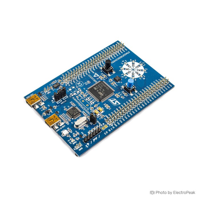
STM32F3 Discovery Board
$28.9500
In stock
SKU
MIC-02-008
Volume discounts:
- +10 3 % $27.9700
- +25 5 % $27.4700
- +50 7 % $26.9800
- +100 8 % $26.4900
- +300 10 % $26.0000
Product Variations:


Add an Accessory:


Ships in 2-3 business days, then:
Free delivery in 12-15 days by Tracked Economic Shipping on orders over $100.
Free delivery in 7-10 days by Express Shipping on orders over $300.
More shipping info

Shop with confidence Learn More
 STM32F429I Discovery Board Previous
STM32F3 Discovery Board Review
The STM32F3 Discovery Board is an educational STM32F303VCT6 development board built around a 72 MHz ARM Cortex-M4. It combines onboard ST-LINK/V2 programming and debugging, motion sensors, LEDs, pushbuttons, USB Mini-B connectivity, and an extension header exposing all LQFP100 I/Os.
It suits Cortex-M4 learning, sensor-fusion experiments, and external-circuit prototyping. Before ordering, account for revision-dependent sensor hardware, the older Mini-B connector, and uncertainty around the physical reset-button arrangement. A reported retail range is $20–30, but this is not a current price.
For related platforms, browse our STM32 development boards.
Specifications of STM32F3 Discovery Board
- Microcontroller: STM32F303VCT6
- Core: ARM Cortex-M4
- Operating frequency: 72 MHz
- Flash memory: 256 KB
- RAM: 48 KB
- Debug tool: ST-LINK/V2
- Debug mode: standalone
- Gyroscope: L3GD20
- Gyroscope type: 3-axis digital output
- Sensor: LSM303DLHC
- Acceleration sensor: 3D digital linear acceleration sensor
- Magnetic sensor: 3D digital magnetic sensor
- LED1: red
- LED1 voltage: 3.3 V
- LED2: red/green
- LED2 function: USB communication
- User LEDs: LD3/10 red
- User LEDs: LD4/9 blue
- User LEDs: LD5/8 orange
- User LEDs: LD6/7 green
- Pushbuttons: two
- Pushbutton types: user and reset
- Power supply: USB bus
- Power supply: external 3 V supply voltage
- Power supply: external 5 V supply voltage
- External application power supply: 3 V
- External application power supply: 5 V
- Connector: USB Mini-B
- Extension header: all LQFP100 I/Os
- Package: LQFP100
- STM32F313xx support: not supported
STM32F3 Discovery Specifications Explained
The STM32F303VCT6 gives this STM32F3 board a 72 MHz Cortex-M4 platform for GPIO, timers, sensor interfaces, floating-point calculations, and DSP-oriented firmware. Its 256 KB Flash provides firmware storage, while the 48 KB RAM figure sets the practical limit for runtime buffers, middleware, and processed sensor data.
That 48 KB is not a uniform memory pool. It consists of 40 KB SRAM plus 8 KB CCM-RAM, a closely coupled memory region useful for selected time-sensitive data but not interchangeable with general SRAM in every application.
| Specification | Why it matters |
|---|---|
| ARM Cortex-M4 at 72 MHz | Supports a practical learning platform for real-time embedded work, including timers, sensor processing, control loops, and floating-point calculations. |
| 256 KB Flash and 48 KB RAM | Provides room for moderate firmware and sensor-processing buffers, but larger applications still need careful memory planning. |
| 40 KB SRAM plus 8 KB CCM-RAM | Explains why memory placement matters. CCM-RAM can help selected routines and data, but code cannot assume all 48 KB behaves like ordinary SRAM. |
| All LQFP100 I/Os on the extension header | Makes the board useful beyond onboard demonstrations. External sensors, interfaces, and control circuitry can be connected without needing access directly at the MCU package. |
| Gyroscope, acceleration sensing, and magnetic sensing | Supports orientation, compass, tilt, gesture, and 9DOF sensor-fusion work without adding separate motion-sensor modules. Exact sensor chips depend on board revision. |
| Ten LEDs | Useful during bring-up: a simple LED test can confirm that power, programming, and basic GPIO firmware are working before external hardware is added. |
The board is built around STM32F303VCT6, so it does not support STM32F313xx processors. Target STM32F303VCT6 in firmware configuration rather than selecting a nearby STM32F3 device.
For external circuits, a 400-point half-size breadboard provides a convenient prototyping area for extension-header connections. If a compact control board matters more than onboard sensing, the compact STM32F103C8T6 board has a 53 × 22 mm form factor and 37 GPIO pins, but does not provide the Discovery board’s onboard sensors.
Compare other STM32 development platforms when the processor family or onboard hardware drives the decision.
STM32F3 Discovery Sensor Revision and ST-LINK Setup Limits
STM32F3DISCOVERY boards have documented MB1035 PCB revisions from A through E, and the sensor hardware differs between them. Earlier rev A–C boards use the L3GD20 gyroscope and LSM303DLHC acceleration/magnetic sensor, while later rev D/E boards use I3G4250D and LSM303AGR devices.
Check the MB1035-F303C revision marking and the sensor IC markings before loading a legacy sensor example. A driver written for L3GD20 or LSM303DLHC may not work correctly on a board fitted with I3G4250D or LSM303AGR.
| Board detail | Earlier revisions | Later revisions |
|---|---|---|
| Gyroscope | L3GD20 | I3G4250D |
| Acceleration and magnetic sensor | LSM303DLHC | LSM303AGR |
| Debugger implementation | ST-LINK/V2 on rev A/B | ST-LINK/V2-B from rev C onward |
Later ST-LINK/V2-B implementations can add Virtual COM Port and mass-storage capability, but these features are revision-specific and should not be assumed on every board. The onboard debugger supports standalone ST-LINK operation through SWD when the required external-target connection and jumper arrangement are used.
Windows users can encounter a “No ST-LINK detected” message when the ST-LINK USB driver is missing, damaged, or conflicts with libusb or OpenOCD drivers. Install or repair STSW-LINK009 where needed, then reconnect through the ST-LINK Mini-B port using a USB Mini-B data cable.
The board’s 3 V and 5 V output pins are documented for a maximum of 100 mA. Do not use them to supply motors, high-current displays, or several external modules. Use a separate regulated supply for loads beyond that limit. Isolated reports also describe regulator heating under unsuitable external power conditions, another reason to keep external loads off these rails.
The board specification describes two pushbuttons with user and reset functions. Official documentation and schematics instead describe one physical B1 arrangement, with reset behavior involving BOOT0 or power cycling. Verify the delivered revision and layout if a conventional dedicated reset button is required.
For Cortex-M0 learning with an included additional prototyping board, the STM32F0 Discovery for Cortex-M0 learning is the more appropriate direction when the STM32F3 sensor set and memory capacity are not required.
An external STM32 programmer and emulator is optional when a separate debug tool is needed for other STM32 targets.
STM32F3 Discovery vs STM32F407 Discovery
These two Discovery boards target different work. The STM32F3 Discovery centers on motion sensing and I/O experimentation, with onboard gyroscope, acceleration sensing, magnetic sensing, a 72 MHz operating frequency, 256 KB Flash, 48 KB RAM, and access to all LQFP100 I/Os.
The STM32F407 Discovery with Audio instead lists an audio DAC, integrated class D speaker driver, digital microphone, and LIS3DSH 3-axis accelerometer. Choose it for projects centered on audio input, audio output, or microphone-based applications. The F3 board better matches onboard 9DOF orientation work.
| Project need | Better fit | Reason |
|---|---|---|
| Orientation, compass, tilt, or sensor fusion | STM32F3 Discovery | It provides onboard gyroscope, acceleration sensing, and magnetic sensing. |
| External circuits using full LQFP100 I/O access | STM32F3 Discovery | The extension header exposes all LQFP100 I/Os for prototyping. |
| Audio playback, microphone input, or speaker-driver work | STM32F407 Discovery | It lists an audio DAC, class D speaker driver, and digital microphone. |
Choose the STM32F4 Discovery board with onboard audio when its listed audio hardware is central to the project rather than an added peripheral.
STM32F3 Discovery Compatibility and Accessories
This STM32 development board uses USB Mini-B connections. Two Mini-B connectors are documented: one serves the onboard ST-LINK interface, while the other is the USB FS user connection. A Mini-B data cable is required to connect the ST-LINK port to a computer; a Micro-B or USB-C cable will not fit.
| Area | Compatibility or requirement | Buyer implication |
|---|---|---|
| Target MCU | STM32F303VCT6 | Select STM32F303VCT6 in project configuration; STM32F313xx is not supported. |
| Programming and debugging | Embedded ST-LINK/V2 with standalone mode | Supports onboard programming and debugging, plus standalone SWD use. The ST-LINK implementation varies by PCB revision. |
| Windows setup | STSW-LINK009 where required | Windows users may need to install or repair the ST-LINK USB driver. |
| Development environments | STM32CubeIDE, Keil MDK-ARM, IAR EWARM, Arduino IDE through stm32duino, Zephyr, PlatformIO, OpenOCD, and J-Link | STM32CubeIDE is the primary official workflow. Arduino IDE use requires the stm32duino ecosystem rather than a conventional AVR-style Arduino workflow. |
| GPIO logic | 3.3 V logic | Use 3.3 V-compatible peripherals. Incompatible 5 V interfaces need level shifting. |
| External power rails | 3 V and 5 V board outputs limited to 100 mA | Use a separate regulated supply for higher-current peripherals and loads. |
| Ethernet | Not provided | Add an external solution or choose another board if Ethernet is a requirement. |
Required
- USB Mini-B data cable: Required for the ST-LINK connection. No matching Mini-B cable is available here.
- STSW-LINK009 on Windows where needed: Install or repair this ST-LINK USB driver if Windows does not recognize the debugger correctly.
Recommended
- Breadboard prototyping with a 400-point half-size breadboard: Provides a practical workspace for external circuits when using the extension header.
- Jumper-wire connections with the 140-piece kit: Connect header pins to the breadboard and 3.3 V-compatible peripherals.
- 3.3 V-compatible peripherals: Keep GPIO interfacing straightforward and avoid exposing MCU pins to incompatible logic levels.
- Separate regulated supply: Required for loads above the documented 100 mA board-output limit.
Optional
- 3.3 V-to-5 V logic-level shifting: Needed for incompatible external modules.
- USB current measurement: Useful when investigating board and peripheral power use.
- Logic analyzer or oscilloscope: Helpful for SPI, I2C, UART, and signal-debugging work.
Projects that specifically require an Ethernet connector, camera connector, and 4.3-inch capacitive touch LCD are better served by the STM32 Discovery board with Ethernet and touch display.
STM32F3 Discovery Quick Start and First Test
A short LED test verifies the key parts of a new board before sensor code or external hardware complicates troubleshooting.
- Inspect the board silkscreen for the MB1035 revision identifier.
- Confirm that a USB Mini-B data cable is available.
- Connect the computer to the Mini-B port used by the ST-LINK interface.
- Install STSW-LINK009 on Windows if the ST-LINK interface is not detected.
- Open STM32CubeIDE or STM32CubeProgrammer and connect to the STM32F303VCT6 target through the onboard ST-LINK.
- Create or open an STM32F303VCT6 project, then flash a simple LED-blink example.
- Confirm the red 3.3 V power indication and expected LED activity. Identify the sensor ICs before loading sensor examples.
If ST-LINK is not detected, first check that the cable is Mini-B and supports data, that it is connected to the ST-LINK port rather than the USB FS port, and that the Windows driver is not conflicting with libusb or OpenOCD. If an onboard sensor example fails while LED programming works, verify the MB1035 revision and sensor markings before changing the firmware.
USB-connection LED behavior is not a substitute for confirming debugger detection in STM32CubeIDE or STM32CubeProgrammer. Keep external loads disconnected during the first test so a power problem is not mistaken for a programming fault.
STM32F3 Discovery FAQ and Buying Checklist
Does STM32F3 Discovery work with Windows 10 or Windows 11?
Yes, but Windows may need the STSW-LINK009 driver installed or repaired for the embedded ST-LINK interface. “No ST-LINK detected” errors can also result from conflicts with libusb or OpenOCD drivers.
Which sensors are on the STM32F3 Discovery Board?
The specified sensors are the L3GD20 gyroscope and LSM303DLHC acceleration and magnetic sensor. Later rev D/E boards can use I3G4250D and LSM303AGR instead, so check the MB1035 revision marking and chip markings before choosing a sensor library.
Does STM32F3 Discovery have a dedicated reset button?
The specification describes user and reset pushbutton functions, but official documentation and schematics describe one physical B1 arrangement with reset behavior involving BOOT0 or power cycling. Verify the delivered board layout if a conventional dedicated reset button is essential.
Can STM32F3 Discovery run Arduino IDE?
Yes, it can run Arduino IDE through the stm32duino core. Select the STM32F3DISCOVERY target after installing STM32 MCU based board support; this remains an STM32 development workflow rather than an AVR-style Arduino experience.
What USB cable does STM32F3 Discovery use?
It uses USB Mini-B. Two Mini-B connectors are documented, one for ST-LINK and one for USB FS, so a Micro-B or USB-C cable does not fit.
Can the 3 V and 5 V pins power external modules?
Yes, within the documented 100 mA limit for the 3 V and 5 V output pins. Use a separate regulated supply for motors, larger displays, or any load above that limit.
Can STM32F3 Discovery be used as a standalone ST-LINK debugger?
Yes, it supports standalone ST-LINK/V2 operation through SWD. External-target programming depends on the correct SWD connection and relevant jumper arrangement.
Does STM32F3 Discovery support Ethernet?
No, Ethernet is not provided on this platform. For projects needing the listed Ethernet connector, the STM32F746G Discovery with Touch Screen is the appropriate direction.
What is the difference between STM32F3 Discovery and STM32F407 Discovery?
The STM32F3 Discovery suits onboard gyroscope, acceleration, and magnetic-sensing work. The STM32F407 Discovery with Audio lists an audio DAC, integrated class D speaker driver, digital microphone, and 3-axis accelerometer for audio-oriented applications.
Purchase decision summary
- Ideal for: STM32 learners, educators, embedded developers, and sensor-fusion projects needing a 72 MHz Cortex-M4, 256 KB Flash, 48 KB RAM, onboard motion sensing, ST-LINK debugging, and all LQFP100 I/Os on an extension header.
- Maybe for: Arduino IDE users comfortable with stm32duino, motor-control and mixed-signal experimenters adding suitable external hardware, and developers willing to verify the PCB revision before using sensor examples.
- Avoid if: You need fixed sensor hardware across every unit, a clearly dedicated reset button, USB-C or Micro-B connectivity, low-power battery behavior, Ethernet, Wi-Fi, onboard display hardware, onboard audio hardware, or high-current peripheral power from board output rails.
Before you buy
- ✓ Confirm that STM32F303VCT6 and Cortex-M4 are the intended platform.
- ✓ Confirm that 256 KB Flash and 48 KB RAM fit the firmware and buffer requirements.
- ✓ Confirm that onboard gyroscope, acceleration sensing, and magnetic sensing match the project.
- ✓ Confirm that a USB Mini-B data cable is available.
- ✓ Confirm that Windows driver installation is acceptable if using Windows.
- ✓ Confirm that the PCB revision and sensor chips can be checked before using sensor code.
- ✓ Confirm that connected peripherals use 3.3 V logic or include level shifting.
- ✓ Confirm that external loads will not rely on more than the documented 100 mA board-output limit.
- ✓ Confirm that the project does not require Ethernet, Wi-Fi, display, camera, or onboard audio hardware.
- ✓ Confirm whether the project needs a dedicated reset button rather than the documented B1/BOOT0 behavior.
For a built-in 2.4-inch QVGA TFT LCD and 64 Mbits external SDRAM, choose the STM32 Discovery board with built-in LCD and external memory. For a compact 53 × 22 mm control project without onboard Discovery sensors, the STM32F103C8T6 Blue Pill is a better fit.
If the project calls for a different MCU family rather than another STM32 board, the NXP LPC845 Development Board is an alternative ARM microcontroller ecosystem, not a direct STM32F3 replacement. A separate STM32 programmer is optional when programming or debugging additional STM32 targets.
| MCU/SoC | STM32F303VCT6 |
|---|---|
| Product Family | STM32 Discovery |
| Architecture | ARM Cortex-M4 |
| CPU Cores | 1 |
| Clock Speed (MHz) | 72 MHz |
| Flash | 256KB |
| SRAM | 48KB |
| EEPROM | No |
| SPI interface Pins | 3 |
| I2C interface Pins | 2 |
| UART interface Pins | 5 |
| USB Ports | USB mini-B |
| CAN Bus Support | 1 |
| Ethernet Support | No |
| ADC Channels | 4 |
| DAC Channels | 2 |
| Timers Count | 10 |
| Operating Voltage (V) | 3.3V |
| GPIO Voltage (V) | 3.3V |
| Wireless | No |
| Form Factor | Discovery Board |
| Input Voltage (V) | USB or external 3V/5V |
| Antenna Type | No |
| Bluetooth Ver. | No |
Write Your Own Review

Please complete your information below to login.
Sign In
Create New Account