
Product added to cart

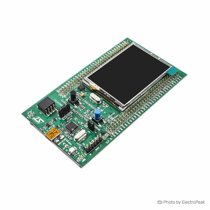
STM32F429I Discovery Board
$60.5000
In stock
SKU
MIC-02-009
Volume discounts:
- +5 4 % $58.1800
- +10 6 % $57.0200
- +25 8 % $55.8600
- +50 10 % $54.7000
- +100 12 % $53.5400
Product Variations:


Add an Accessory:


Ships in 2-3 business days, then:
Free delivery in 12-15 days by Tracked Economic Shipping on orders over $100.
Free delivery in 7-10 days by Express Shipping on orders over $300.
More shipping info

Shop with confidence Learn More
 STM32F746G Discovery Board Previous
STM32F429I Discovery Board Review
The STM32F429I Discovery Board is an educational STM32F4 development and testing board based on the STM32F429ZIT6. Its onboard 2.4" QVGA TFT LCD, 64 Mbits SDRAM, L3GD20 gyroscope, embedded debugger, buttons, LEDs, USB OTG connection, and I/O extension header bring graphics and peripheral development together on one board.
It suits embedded developers working with display output, external memory, motion sensing, and SWD debugging. It is less suited to simple breadboard-first work, low-power final products, Arduino-first workflows, or Ethernet-ready projects without added hardware. Verify the delivered board revision before planning around virtual COM port or USB mass-storage workflows.
For power and programming, use a known data-capable USB to Micro USB Cable - 30cm. See STM32 development boards if another STM32 form factor better matches the project.
STM32F429I Discovery Board Specifications
Specifications of STM32F429I Discovery Board
- Microcontroller: STM32F429ZIT6
- Flash memory: 2 MB
- RAM: 256 KB
- Display: 2.4" QVGA TFT LCD
- External memory: 64 Mbits SDRAM
- Debugger: ST-LINK/V2 embedded debug tool
- Debugger connector: SWD connector
- Sensor: L3GD20
- Sensor type: 3-axis digital output gyroscope
- LEDs: 6
- LED 1: red/green for USB communication
- LED 2: red for 3.3 V power-on
- LED 3: green user LED
- LED 4: red user LED
- LED 5: green VBUS LED
- LED 6: red OC LED
- Power supply: through the USB bus
- Power supply: external 5 V supply voltage
- Interface: USB OTG micro-AB connector
- Header: extension header for I/O pins
- Buttons: user and reset pushbuttons
STM32F429I Discovery Board Specifications Explained
The STM32F429ZIT6, with 2 MB Flash memory and 256 KB RAM, provides the internal platform for STM32F4 firmware, debugging, and peripheral experiments. Flash capacity matters when an application includes middleware, graphics assets, and larger firmware images. Internal RAM still needs careful planning as display buffers and application data grow.
| Hardware area | Why it matters |
|---|---|
| 64 Mbits SDRAM | 64 Mbits equals 8 MBytes. This external memory supports larger graphics buffers, runtime allocations, and SDRAM configuration work beyond internal RAM alone. |
| 2.4" QVGA TFT LCD | The onboard display is useful for compact embedded interfaces, GUI demonstrations, and LTDC display experiments. It requires board-specific LCD initialization before LTDC output, so generic TFT-library assumptions can leave the screen blank. |
| L3GD20 gyroscope | The onboard 3-axis digital output gyroscope allows rotation and motion experiments without first wiring an external sensor. Its board connection uses SPI5 rather than I2C, so the peripheral configuration must match that interface. |
| ST-LINK/V2 and SWD connector | The embedded debug tool supports normal programming and debugging, while SWD supports debugger-based workflows. Revision-specific VCP and mass-storage behavior must be verified separately. |
| LEDs and pushbuttons | The six LEDs plus user and reset pushbuttons provide immediate status indication and simple firmware test I/O before more involved peripherals are enabled. |
| Extension header | The header enables external sensors, modules, and prototype circuits, but this is not an Arduino-header development board and is less convenient for breadboard-first work. |
| Power provisions | The stated power options are through the USB bus or an external 5 V supply voltage. Select the connection method that matches the development setup. |
A Breadboard Jumper Wire Kit - 140 Pieces pairs with the extension header for external connections. For projects needing a 4.3-inch 480x272 display, 128-Mbit SDRAM, Ethernet, a camera connector, and Arduino Uno V3 expansion headers, the STM32F746G Discovery with Touch LCD is the better fit.
STM32F429I Discovery Board Setup and ST-LINK Verification
Begin with the ST-LINK USB connection, not the USB OTG connector. Install STM32CubeIDE and the required ST-LINK USB drivers for the host operating system, then connect a data-capable micro-USB cable and confirm that the debugger is detected.
- Install STM32CubeIDE and ST-LINK USB drivers where the host operating system requires them.
- Connect a data-capable micro-USB cable to the ST-LINK connection.
- Confirm that the ST-LINK debugger appears on the host computer.
- Update ST-LINK firmware if prompted by the development tools.
- Open or create an STM32F429ZI project.
- Build and flash a basic LED or board-support example.
- Confirm the expected LED behavior or debugger connection before enabling the LCD, SDRAM, gyroscope, or USB OTG functions.
A detected debugger and a successfully flashed simple test confirm the basic programming path. If STM32CubeIDE does not detect ST-LINK, first rule out a charging-only cable, an unreliable USB port, missing drivers, outdated ST-LINK firmware, or competing driver conflicts. A reliable USB power source or powered hub can help when a host port is unstable.
STM32Cube HAL/LL and board support packages are the intended development path. Keil MDK-ARM, IAR EWARM, GCC/Make, Zephyr RTOS, NuttX, and mbed OS on DISC1 are also reported workflows; Arduino IDE support is limited and community-driven. For a dedicated debug arrangement or external STM32 targets, use a Waveshare ST-LINK V2 (mini) - STM Programmer & Debugger.
STM32F429I Discovery Board I/O and Project Limits
The extension header supports external I/O work, but a complete header pinout and the pins reserved by onboard peripherals are not provided here. Plan header use carefully when combining external modules with the LCD, gyroscope, debugging connection, and other onboard functions.
USB OTG support is provided through the listed USB OTG micro-AB connector. Documentation and board-photo references differ on the physical connector form, so inspect the delivered connector before buying an OTG-specific cable.
The STM32F429ZIT6 has Ethernet capability at MCU level, but this board has no documented onboard Ethernet PHY or RJ45 connector. A wired network project needs an external PHY or module, connector, wiring, and suitable software support. No onboard audio hardware, CAN transceiver, camera connector, or external wireless radio is listed.
This is a development platform rather than a battery-optimized final-product design. Jumper wires can connect it to a 400 Points Half Size Breadboard - 5.5x8.5cm, but the layout is less convenient for breadboard-first prototyping than boards with Arduino-compatible headers. If Ethernet, a camera connector, Arduino Uno V3 expansion headers, a larger touch display, or 128-Mbit SDRAM are central requirements, choose the STM32F746G Discovery with Touch LCD.
STM32F429I Discovery Board Limitations and Revision Checks
The board specification identifies an embedded ST-LINK/V2 debug tool. Two board revisions need to be distinguished: the older STM32F429I-DISCO uses ST-LINK/V2, while the newer STM32F429I-DISC1 uses ST-LINK/V2-B.
VCP serial-over-USB and USB mass-storage support are associated with the DISC1/ST-LINK/V2-B revision, not the older DISCO/ST-LINK/V2 revision. Confirm that the delivered board is marked DISC1, or obtain confirmation before relying on a virtual COM port or drag-and-drop programming workflow.
The LCD is not a generic plug-and-play TFT workflow. Its controller initialization must complete before LTDC output can drive the display. The L3GD20 also needs the correct SPI5 configuration; configuring it as an I2C device prevents normal communication.
Some users report ST-LINK detection and enumeration problems caused by unsuitable cables, weak USB ports, driver conflicts, or outdated firmware. Treat these as first troubleshooting checks rather than a universal board fault. One user reported gyroscope output staying at zero despite SPI identification working; correct initialization and official BSP code were the reported remedy. One report also describes a TouchGFX/CubeIDE coexistence issue affecting ST-LINK detection, but that should not be taken as a universal defect.
For separate debugging or programming work beyond the onboard path, the ST-Link V3MINIE STM8/STM32 Programmer & Emulator is an optional standalone tool.
STM32F429I Discovery Board Alternatives and Revision Choices
Choose alternatives by the onboard hardware the project actually needs, not by a general “newer is better” assumption.
| Board | Choose it when | Relevant difference |
|---|---|---|
| STM32F407 Discovery with Audio | Onboard audio, microphone, or audio output hardware is the project requirement. | It has 1 MB Flash, 192 KB RAM, an accelerometer, digital microphone, audio DAC, and class D speaker driver. Choose this F429I board instead when the QVGA LCD and 64 Mbits SDRAM are the relevant onboard features. |
| STM32F3 Discovery with Gyroscope | Orientation, magnetic sensing, accelerometer, and gyroscope work are central. | It has a 72 MHz Cortex-M4 core, 256 KB Flash, a gyroscope, magnetic sensor, and accelerometer. It is not a direct replacement for graphics-and-SDRAM development. |
| STM32F746G Discovery with Touch LCD | Larger graphics, Ethernet, camera, or Arduino-header requirements drive the design. | It provides a Cortex-M7 core, 4.3-inch 480x272 capacitive touch LCD-TFT, 128-Mbit SDRAM, Ethernet, camera connector, and Arduino Uno V3 expansion headers. |
| STM32F103C8T6 Blue Pill | A compact STM32F1 minimum-system board is needed for basic ARM development. | Its 53 × 22 mm board has 64 KB Flash, 20 KB SRAM, and 37 GPIO ports. It is a smaller platform, not a feature-equivalent Discovery board. |
| Nucleo-F429ZI | Breadboard-friendly Arduino-compatible headers are more important than integrated display, SDRAM, and gyroscope hardware. | This is an unlinked reference rather than a supplied product. It is considered a more breadboard-friendly approach, while the Discovery board integrates the LCD, SDRAM, and gyroscope. |
DISCO versus DISC1 is a revision check, not a standard upgrade claim. DISC1 is the current revision and is associated with ST-LINK/V2-B, VCP, and mass-storage features; confirm the marking on the board supplied.
Accessories
Required
- USB to Micro USB Cable - 30cm for USB power, programming, and data connection. Confirm whether a cable is included, as package contents are not stated.
- STM32CubeIDE installation for the normal development environment.
Recommended
- Jumper wires for external header, Boot0, and SWD wiring.
- A breadboard for external circuit prototyping.
- A separate programmer/debugger for external STM32 targets or a dedicated debug setup.
- A reliable USB power source or powered USB hub if host-port stability is poor.
Optional
- A standalone STM32 programming and emulation tool for projects that need one beyond the onboard workflow.
- An external Ethernet PHY or module and connector for wired network projects.
- Additional I2C or SPI sensors for external peripheral work.
- A logic analyzer for SPI, I2C, timing, and peripheral debugging.
- An external 5 V power supply for standalone operation.
Frequently Asked Questions
Does the STM32F429I Discovery Board have serial over USB?
It depends on the board revision. VCP support is associated with the DISC1 revision using ST-LINK/V2-B, while older DISCO boards with ST-LINK/V2 should not be assumed to provide it. Verify the delivered board marking first.
What is the difference between STM32F429I-DISCO and STM32F429I-DISC1?
DISCO is the older revision with ST-LINK/V2, while DISC1 is the newer revision with ST-LINK/V2-B. DISC1 is associated with VCP and USB mass-storage support, but the delivered board marking is not stated.
How much usable external memory does 64 Mbits SDRAM provide?
64 Mbits SDRAM equals 8 MBytes. That capacity is useful for QVGA graphics buffers, GUI work, RTOS allocations, and SDRAM learning.
Does the STM32F429I Discovery Board have Ethernet?
No onboard Ethernet PHY or RJ45 connector is documented. Ethernet projects require additional hardware, even though the MCU has Ethernet capability at the chip level.
Which interface does the onboard L3GD20 gyroscope use?
The onboard L3GD20 uses SPI5. Configure SPI5 or start with the board-specific BSP rather than treating the sensor as an I2C device.
Why is STM32CubeIDE not detecting ST-LINK?
First check the USB cable, port, drivers, and ST-LINK firmware. Use a data-capable cable, try a reliable USB port, install required drivers, update firmware when prompted, and resolve driver conflicts if present.
Can the STM32F429I Discovery Board program another STM32 target?
Yes. The embedded ST-LINK can be used as a standalone programmer/debugger for an external target with the required jumper configuration. The board includes an SWD connector for debug workflows.
Is this board suitable for Arduino IDE projects?
It is not the preferred Arduino-first choice. Arduino support is limited and community-driven; STM32Cube HAL/LL and STM32CubeIDE are more appropriate for this board.
Why does the LCD remain blank after code compiles?
A blank LCD commonly indicates missing board-specific initialization rather than a failed display. Start with STM32Cube BSP or official example code because controller initialization must run before LTDC display output.
What do I need besides the board to get started?
You need a data-capable micro-USB cable, STM32CubeIDE, and ST-LINK drivers where required. Jumper wires and a breadboard help with extension-header projects, while Ethernet work also needs external network hardware.
Purchase Decision Summary
Ideal for
STM32F4 developers building QVGA display, graphics, external SDRAM, gyroscope, USB OTG, SWD debugging, and board-support-package projects.
Maybe for
Intermediate students learning STM32Cube HAL/LL who are prepared for peripheral configuration, board-specific initialization, and revision checks.
Consider another option if
You need onboard Ethernet, built-in wireless, a simple Arduino-first workflow, battery-focused deployment, confirmed breadboard-friendly headers, or guaranteed VCP and mass storage without verifying the delivered revision.
Buying Checklist
- ✓ Confirm whether the delivered board is marked DISCO or DISC1.
- ✓ If serial-over-USB or drag-and-drop programming is required, verify DISC1/ST-LINK/V2-B capability before purchase.
- ✓ Confirm whether a data-capable micro-USB cable is included.
- ✓ Plan for STM32CubeIDE and ST-LINK driver installation.
- ✓ Account for 64 Mbits SDRAM as 8 MBytes in memory planning.
- ✓ Choose this board when the 2.4" QVGA TFT LCD, external SDRAM, and onboard gyroscope match the project.
- ✓ Add jumper wires and a breadboard for external I/O experiments.
- ✓ Add external Ethernet hardware for wired network projects.
- ✓ Do not assume Arduino compatibility or generic LCD-library compatibility.
- ✓ Confirm connector details before buying USB OTG-specific cables or enclosure hardware.
| MCU/SoC | STM32F429ZIT6 |
|---|---|
| Product Family | STM32 Discovery |
| Architecture | ARM Cortex-M4 |
| CPU Cores | 1 |
| Clock Speed (MHz) | 180 MHz |
| Flash | 2 MB |
| SRAM | 256 KB |
| External Memory | 64 Mbit SDRAM |
| GPIO Pins | 144-pin LQFP |
| SPI interface Pins | 6 |
| I2C interface Pins | 3 |
| UART interface Pins | 4 |
| USB Ports | USB OTG micro-AB |
| CAN Bus Support | 2 |
| Ethernet Support | No |
| ADC Channels | 3x 12-bit ADC |
| DAC Channels | 2x 12-bit DAC |
| Timers Count | 17 |
| Operating Voltage (V) | 3.3V |
| GPIO Voltage (V) | 3.3V |
| Wireless | No |
| IDE Support | GCC-based IDEs, IAR, Keil |
| Input Voltage (V) | USB or external 5V power supply |
| Antenna Type | No |
| Bluetooth Ver. | No |
Write Your Own Review

Please complete your information below to login.
Sign In
Create New Account