
Product added to cart

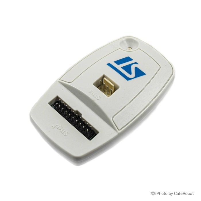
ST-Link V2/JTAG Programmer for STM8 & STM32
SAVE
As low as $14.5000
In stock
Only %1 left
SKU
PRO-01-043
Ships in 2-3 business days, then:
Free delivery in 12-15 days by Tracked Economic Shipping on orders over $100.
Free delivery in 7-10 days by Express Shipping on orders over $300.
More shipping info

Shop with confidence Learn More
 SOP8 to DIP8 Clips Programmer Previous
ST-Link V2 STM32 Programmer Review
The ST-Link V2/JTAG Programmer for STM8 & STM32 is a USB 2.0 programming and debugging interface for STM8 and STM32 microcontrollers. It provides single-wire communication for STM8 chips and wired JTAG or Serial Wire Debug (SWD) connections for 32-bit ARM targets. It suits developers who can verify the specific board revision, header layout, and target connection requirements before wiring it into a project.
On the bench, this programmer is used to flash firmware onto STM32 breakout boards, step through code on custom hardware via SWD, or maintain legacy 8-bit STM8 designs over SWIM. For engineers pairing it with a standard prototype target, the STM32F103C8T6 ARM Minimum System Development Board provides a straightforward 4-pin SWD header for initial setup. The hardware covers the primary ST microcontroller families, but the listing does not verify genuine STMicroelectronics origin, physical JTAG implementation on this specific build, or documented power-supply output for external targets. Check these details against your intended toolchain: STM32CubeProgrammer or ST-LINK Utility for STM32, and STVP for STM8. That confirmation helps ensure the tool fits your bench requirements. Compare other architectures and interfaces in the microcontroller programmers category.
Specifications of ST-Link V2/JTAG Programmer for STM8 & STM32
- Product type: Programmer and debugger
- Target families: STM8 and STM32
- Communication: single-wire communication
- Debug interface: JTAG/serial wired interface
- USB version: USB 2.0
- Power supply: 5V through USB connector
- USB cable: Standard A to Mini B
- Programming support: FLASH ROM
- Programming support: EEPROM
- Programming support: AFR
- Programming support: bit memory
- Operating temperature: 0 to 50 degrees Celsius
- SWIM supported voltage: 1.65 to 5.5 volts
- SWIM mode support: low-speed mode
- SWIM mode support: high-speed mode
- SWIM programming speed: 9.7 Kbytes/s at low speed
- SWIM programming speed: 12.8 Kbytes/s at high speed
- JTAG supported voltage: 1.65 V to 3.6 V
- JTAG input voltage: 5 volts
- JTAG cable: standard 20-pin 2.54 mm JTAG connector
- LED indicator: flashing during communication with the computer
- STM8 support: all STM8 families with SWIM
- STM32 support: JTAG / SWD interface
- Software support: STVD
- Software support: ATOLLIC
- Software support: IAR
- Software support: Keil
- Software support: TASKING environment
ST-Link V2 Programmer Specifications Explained
Using an ST-Link V2 effectively means separating its host connection, target interfaces, and operating parameters. The programmer connects to the host PC through USB 2.0 and draws operating power directly from the 5V USB bus. On the target side, the protocols are distinct: STM8 devices use the Single Wire Interface Module (SWIM), while STM32 microcontrollers use JTAG or SWD. Memory support covers standard on-chip FLASH ROM and EEPROM, along with alternate function registers (AFR) and bit memory operations supported by ST microcontrollers.
| Listed Specification | Practical Meaning | Buyer Check |
|---|---|---|
| Target families: STM8 and STM32 | Microcontroller architectures handled by the probe's internal firmware. | STM8 requires SWIM lines; STM32 uses SWD or JTAG lines. They do not share the same physical pinout. |
| USB 2.0 / 5V USB power | The host connection runs at standard USB 2.0 speeds and supplies operating power to the programmer probe itself. | Does not confirm that the probe safely powers the target board; verify external target power separately. |
| Standard A to Mini B cable | Physical host connection port on the programmer housing. | Verify whether the cable is present in your toolkit or supplied with your package. |
| SWIM speed: 9.7 to 12.8 Kbytes/s | Flashing throughput for STM8 microcontrollers in low-speed and high-speed modes. | These metrics represent raw write speeds and do not reflect interactive debugging overhead. |
| Memory: FLASH, EEPROM, AFR, bit memory | Hardware support for programming non-volatile program memory, data storage, and configuration registers. | Ensure target registers and security bits are supported by the software suite in use. |
| Operating temperature: 0 to 50 °C | Standard operating thermal envelope for desktop and lab environments. | Avoid enclosed industrial installations where ambient temperatures exceed 50 °C. |
| LED indicator | Flashes to indicate active data exchange across the USB bus to the computer. | Activity indicates host communication, not that the target microcontroller has been successfully located. |
ST-Link V2 STM8 STM32 Compatibility and Software
Microcontroller families in the ST ecosystem require different toolchains and connection protocols. For 8-bit STM8 targets, communication uses SWIM with ST Visual Programmer (STVP) or the ST Visual Develop (STVD) environment. For 32-bit STM32 chips, programming requires STM32CubeProgrammer or the legacy ST-LINK Utility. Debugging is supported across toolchains including Keil MDK, IAR Embedded Workbench, ATOLLIC TrueSTUDIO, and TASKING.
| Target Family | Required Interface | Supported Software | Host Interface | Buyer Checks |
|---|---|---|---|---|
| STM8 | SWIM (Connector B) | STVP, STVD | USB 2.0 (Mini B) | Confirm target operates within 1.65 V to 5.5 V and verify header pin positions. |
| STM32 | SWD / JTAG (Connector A) | STM32CubeProgrammer, ST-LINK Utility, Keil, IAR, ATOLLIC, TASKING | USB 2.0 (Mini B) | Confirm SWDIO and SWCLK lines; use target VCC as a voltage reference. |
ST host operating-system driver documentation covers genuine ST-LINK/V2 devices on x86 and amd64 versions of Windows 10 and Windows 11. Support for Windows on ARM64 systems is not confirmed and should not be assumed for this hardware. Generic and compatible implementations can also encounter recognition issues under modern versions of STM32CubeProgrammer if the probe lacks a valid internal factory serial identity.
For makers building around an STM32F103C8T6 practice target, step-by-step setup guides cover both bare-metal and hobby frameworks. See getting started with the STM32F103C8T6 for pin mapping, or review programming an STM32 Blue Pill with Arduino IDE to configure the board with an ST-Link toolchain. Need a modern native USB Type-C interface, documented target-voltage detection up to 3.6 V, and a dedicated serial console? Consider the ST-Link V3MINIE for USB-C, Virtual COM Port, and higher-speed debugging.
ST-Link V2 JTAG, SWD and SWIM Limitations
The product specification lists SWIM, JTAG, and SWD interfaces, but several hardware and protocol limits deserve attention before this programmer becomes part of a workbench setup.
Exact manufacturer identity, board revision, internal component layout, and enclosure labeling are not documented for this specific hardware release. Generic ST-Link V2 units frequently differ from original STMicroelectronics designs: they may omit bidirectional level-shifting buffers and transient voltage suppression diodes, which changes how logic levels are handled. The listed SWIM voltage range is 1.65 V to 5.5 V, and the listed JTAG voltage range is 1.65 V to 3.6 V, but actual protection levels depend on the supplied board revision. Do not treat the 5V USB power supply specification as a verified, current-limited power-supply output for external circuitry. Power the target microcontroller from its own dedicated, regulated supply, and connect target VCC to the programmer strictly as a logic-level reference unless your hardware documentation explicitly verifies power-output capability.
Physical connector implementation is another critical variable. The listing references a standard 20-pin 2.54 mm JTAG connector, but generic ST-Link units can package connections into a compact pin header that exposes only SWD and SWIM lines while omitting full multi-pin JTAG routing. If your design requires full JTAG testing rather than standard 2-wire SWD, inspect the physical header before purchase. For wider ARM ecosystems that require hardware breakpoints or unique probe serialization across multiple units, the ARM debugger with unique ID support and unlimited flash breakpoints is a purpose-built alternative.
Do not conflate signal definitions: Serial Wire Debug (SWD) is a low-level hardware debugging protocol, not an asynchronous UART serial port. If your application code prints diagnostic messages over standard serial, this programmer will not capture them. A separate USB-to-TTL serial adapter is necessary to monitor console data. Use caution with firmware updates as well. Official programming tools often prompt users to upgrade ST-Link firmware upon connection, but third-party and generic units may lose functionality or fail entirely if an official ST firmware image overwrites an unverified bootloader. Confirm stable tool communication and device identity before attempting any firmware modification.
Keep bench signal paths short to avoid capacitive loading on SWCLK lines. Dedicated jumper wires for SWD and SWIM connections help keep SWDIO, SWCLK, NRST, and GND paths short, clear, and labeled.
ST-Link V2 Programmer Setup, Wiring and Accessories
Complete this verification sequence before starting complex flashing operations:
- Connect the programmer to the computer using a Standard A to Mini B USB cable.
- Install the required device drivers along with STM32CubeProgrammer or ST-LINK Utility (for STM32) or STVP (for STM8).
- Verify that the host operating system recognizes the probe in Device Manager or system logs, and that the LED blinks during communication.
- Examine the programmer pinout on the physical housing or PCB silkscreen to locate the ground, power, and signal pins.
- For STM32 SWD targets, connect SWDIO, SWCLK, GND, and the target reference voltage (VCC); wire the NRST pin if you need hardware reset recovery.
- For STM8 targets, connect the verified SWIM pin, GND, and target reference voltage. (Note: the listing guidance mentions connecting pins 1 and 19 with a jumper when required for STM8 programming; confirm this against your specific target hardware before bridging pins.)
- In your software, select the corresponding communication protocol (SWD for STM32, SWIM for STM8; select JTAG only if verified on the physical hardware).
- Perform a basic target connect or read operation to verify that the toolchain detects the microcontroller ID before attempting to erase or flash firmware.
The host programming tool establishes communication with the ST-Link probe first. Only after probe enumeration is verified will the software attempt to locate the target microcontroller. If the tool detects the probe but not the target, check for reversed SWDIO and SWCLK lines, missing common ground, floating reset pins, or target power loss. For prototyping and connection tests, an 830 points breadboard with organized jumper wires for SWD and SWIM connections provides a stable bench layout. For a full STM32 development-board walkthrough, see the STM32F103C8T6 getting-started guide or review programming an STM32 Blue Pill with Arduino IDE.
Required and Recommended Accessories
- Target board with accessible debug pins (Required): A board such as the STM32F103C8T6 SWD practice target provides dedicated header pins for power, ground, SWDIO, and SWCLK.
- Interconnect wires (Required): A set of jumper wires for SWD and SWIM connections provides flexible, labeled routing between the programmer pins and target headers.
- USB Host Cable (Required): A Standard A to Mini B USB cable is required to connect the programmer to the host machine (verify cable inclusion with your order).
- Software and Drivers (Required): STM32CubeProgrammer, ST-LINK Utility, or STVP must be downloaded and installed on your host system.
- Target Power Supply (Required): Use a stable, external regulated power supply suited to your microcontroller's operating voltage.
- Prototyping Area (Recommended): An 830 points breadboard helps maintain stable physical connections during flashing and debugging.
- Reset Wire (Recommended): A connection to the target microcontroller's NRST pin supports connect-under-reset recovery.
- Multimeter (Recommended): Use an instrument to verify rail voltages and continuity before applying power to the debug lines.
- USB-to-UART Adapter (Optional): A separate serial bridge captures console output or serial bootloader traffic.
- 20-pin JTAG Ribbon Cable (Optional): Required only if your specific programmer variant physically provides a standard 20-pin IDC connector and your target requires full JTAG.
ST-Link V2 vs V3 and Other Debuggers
Select the programming probe around the target processor family, host interface standards, debugging speeds, and auxiliary functions such as virtual serial communication. The table below outlines technical distinctions between this programmer and alternative options in the catalog.
| Model | Tier | Target Architecture | Debug Interfaces | Host Interface & Power | Differentiating Characteristics |
|---|---|---|---|---|---|
| ST-Link V2 (This Board) | Base | STM8, STM32 | SWD, SWIM, JTAG (listed) | USB 2.0 Mini B, 5V probe power | Legacy toolchain support (STVD, STVP, Keil, IAR); standard STM8 and STM32 coverage. |
| Waveshare-branded ST-LINK V2 Mini option | Exact | STM8, STM32 | SWD, SWIM | USB 2.0 Type-A dongle | Features an integrated 500mA self-recovery fuse and provides documented 3.3V and 5V power outputs. |
| aluminum-shell ST-Link V2 with included SWD lead set | Exact | STM8, STM32 | SWD, SWIM, JTAG (up to 4 Mbps) | USB 2.0 Type-A U-disk style | Enclosed in an aluminum alloy shell with DuPont wires; pinout order is laser-engraved on the casing. |
| ST-Link V3MINIE for USB-C, Virtual COM Port, and higher-speed debugging | Variant | STM8, STM32 | SWD/SWV (up to 24 MHz), JTAG (up to 21 MHz) | USB Type-C (High-Speed) | Includes an STDC14 connector with flat cable, 15 Mbps Virtual COM Port, drag-and-drop flash, and 1.65V–3.60V support. |
| ARM debugger with unique ID support and unlimited flash breakpoints | Variant | Broad ARM Cortex | SWD (4-pin header) | Micro USB | J-Link OB architecture featuring unique serialization for multi-device bench setups and unlimited flash breakpoints. |
| AVR and 8051 programmer option | Adjacent | Atmel AVR, 8051 | ISP (6-pin / 10-pin) | USB Type-A dongle | Dedicated to flashing program memory, EEPROM, and fuse bits on AVR and 8051 MCUs; does not debug ARM. |
| Nuvoton programming tool | Adjacent | Nuvoton (8051, Cortex-M0/M4) | ICP / SWD | USB | Proprietary interface supporting offline mass production programming from internal memory without a host PC. |
| PIC and dsPIC programmer option | Adjacent | Microchip PIC, dsPIC | ICSP (RJ-11 header) | USB Mini B | Dedicated to Microchip microcontrollers inside MPLAB; features Programmer-to-Go memory flashing up to 512KB. |
ST-Link V2 Programmer FAQ and Buying Checklist
Frequently Asked Questions
Is this a genuine STMicroelectronics ST-LINK/V2?
This product is an ST-Link V2-compatible programmer rather than a verified genuine STMicroelectronics unit. The listing does not specify an official ST order code, hardware revision, or serial registration. For environments requiring verified electrical protection and direct ST warranty coverage, consider official hardware alternatives.
Can this ST-Link V2 program both STM8 and STM32 microcontrollers?
Yes. It contains firmware routines for communication with both families. STM8 chips use the single-wire SWIM interface, while STM32 microcontrollers use SWD or JTAG connections.
Does this ST-Link V2 really support JTAG, SWD, and SWIM?
The listing specifications state support for all three protocols, but physical header availability can differ across compatible hardware builds. Some compact ST-Link V2 dongles route only SWD and SWIM connections to their exterior pins. Check the connector layout if your application strictly requires multi-wire JTAG.
Can I power my STM32 board from this programmer?
Do not rely on the programmer to supply operating current to your target board. The listing states 5V USB power for the probe itself, but it does not specify target-voltage output limits or protective fuses. Power the target board from its own regulated source and connect target VCC only as a logic reference.
What do I wire for STM32 SWD programming?
A standard SWD setup requires four connections: SWDIO, SWCLK, Ground (GND), and Target Reference Voltage (VCC). Add a wire between the programmer's NRST pin and the target's reset pin if you need to recover chips with disabled debug pins or sleep modes.
Why does STM32CubeProgrammer say “No ST-LINK detected”?
This message indicates a communication breakdown between the computer and the programmer probe. Check that the USB cable is fully seated, verify that the ST-Link USB driver is properly installed in Windows Device Manager, and try an alternate USB port on the motherboard.
Why does the tool say “No STM32 target found” when the probe is detected?
This error means the computer sees the programmer, but the programmer cannot find the target microcontroller. Inspect the SWDIO and SWCLK lines to ensure they are not reversed, confirm that the target board is powered on, verify a shared ground connection, and shorten your jumper leads.
Does this ST-Link V2 work on Windows 11?
ST-Link V2 hardware functions under 64-bit (x86/amd64) Windows 11 when using current ST drivers. Driver availability is not established for Windows 11 running on ARM64 processors.
Does “serial wire” mean I get a UART COM port for serial logs?
No. Serial Wire Debug (SWD) is a synchronous debugging bus, not an asynchronous UART serial port. If your application code transmits data over serial (TX/RX), you need a separate USB-to-UART adapter to view that console output.
Should I update the firmware immediately after receiving it?
Do not immediately apply firmware updates through official ST tools. Generic and compatible probes may not contain official bootloaders, and an official firmware overwrite can permanently disable the device. Update only if required and after confirming device recognition.
What is a better option if I need USB-C, Virtual COM Port, or faster debugging?
The ST-Link V3MINIE for USB-C, Virtual COM Port, and higher-speed debugging provides a native USB Type-C connector, debugging speeds up to 24 MHz, and an integrated 15 Mbps Virtual COM Port for serial communication.
Purchase Decision Summary
- Ideal for: Developers working with STM8 and STM32 microcontrollers who need a functional, USB-connected programming tool and are comfortable checking physical pin assignments and providing external target power.
- Maybe for: Flashing standard development boards like the Blue Pill, programming custom boards with exposed SWD pads, or working on legacy STM8 projects with verified SWIM wiring.
- Avoid if: You need guaranteed genuine STMicroelectronics hardware, verified full 20-pin JTAG, onboard target power delivery, an integrated UART debugging console, or native support for Windows on ARM64. For an AVR chip, look at the AVR and 8051 programmer option; for Nuvoton devices, use a Nuvoton programming tool; and for Microchip devices, choose a PIC and dsPIC programmer option. Compare architectures in the microcontroller programmers category.
Pre-Purchase Checklist
- Confirm your target microcontroller is an STM8 or STM32 device.
- Determine whether your target hardware requires SWIM (STM8), SWD (STM32), or JTAG.
- Ensure your target board exposes the necessary pins (SWDIO, SWCLK, GND, and VCC reference).
- Verify that you have an independent, regulated power supply for your target microcontroller board.
- Check that you have a Standard A to Mini B USB cable available.
- Verify that your host system is running an x86/amd64 operating system compatible with ST development tools.
- Prepare a separate USB-to-TTL serial adapter if your project requires UART console logging.
- Confirm that you are comfortable operating a compatible programmer without requiring official ST serial identity verification.
| Interface Type | USB |
|---|---|
| Operating Voltage (V) | 5V |
| Operating Temp (°C) | 0 to 50 °C |
| Interface Category | Programmer Adapter |
| Output Type | Digital |
| Chipset | ST-LINK/V2 |
| Voltage Range | 1.65V to 5.5V |
| Protocols | JTAG, SWD, SWIM, Serial |
Write Your Own Review

Please complete your information below to login.
Sign In
Create New Account