
Product added to cart

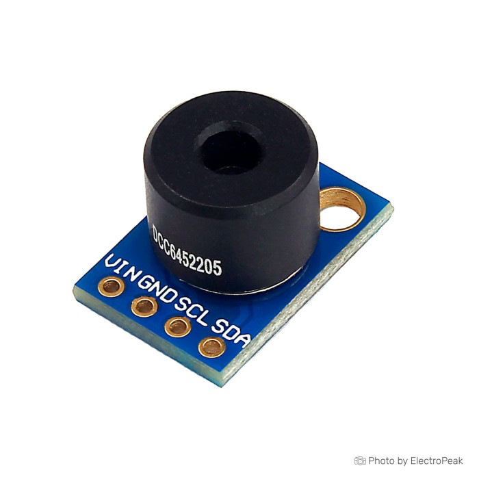
MLX90614 GY-906-BCC Infrared Temperature Sensor Module
$7.9500
In stock
SKU
SEN-10-103
Volume discounts:
- +25 4 % $7.6200
- +50 6 % $7.4500
- +100 8 % $7.2900
- +300 10 % $7.1200
- +500 13 % $6.9500
Ships in 2-3 business days, then:
Free delivery in 12-15 days by Tracked Economic Shipping on orders over $100.
Free delivery in 7-10 days by Express Shipping on orders over $300.
More shipping info

Shop with confidence Learn More
 LM35 Analog Temperature Sensor Module Previous
MLX90614 GY-906-BCC Infrared Temperature Sensor Review
The MLX90614 GY-906-BCC is a non-contact infrared temperature sensor module that reads surface temperatures without physical contact through a two-wire I2C interface. Its factory-specified 35° field of view suits microcontrollers monitoring machinery, heated surfaces, or automated process points where one averaged reading is sufficient. It is not intended for thermal imaging, medical-grade diagnostics, or resolving small targets at long range.
Within our Temperature & Humidity catalog, non-contact infrared sensors address situations where probe placement is impractical or hazardous. The way this sensor gathers data determines the optical and electrical layout needed for reliable measurements.
Specifications of MLX90614 GY-906-BCC Infrared Temperature Sensor Module
- Input voltage: 5 VDC
- Measurement temperature: -40°C to +125°C for sensor temperature
- Measurement temperature: -70°C to +380°C for object temperature
- Accuracy: 0.5°C in the temperature range 0°C to +50°C
- Resolution: 0.02°C
- Interface: I2C
- Field of View (FoV): 35°
- Thermal Gradient Compensated feature
MLX90614 GY-906-BCC Specifications and Measurement Limits
Every infrared thermometer measures radiated thermal energy within an optical cone, not at a microscopic pinpoint. The MLX90614 GY-906-BCC uses a 35° field of view (FoV), so its internal thermopile averages the temperature of everything inside that cone. For an accurate reading of the intended subject, the target must completely fill the 35° field of view. If a target is too small or too far away, surrounding background surfaces enter the cone and skew the reported value toward the background temperature.
Measurement resolution and real-world accuracy are easy to confuse. The stated 0.02°C resolution is the internal digital output step size of the processing circuitry, not measurement uncertainty. Real-world accuracy is specified at 0.5°C across the 0°C to +50°C range under settled, isothermal operating conditions with a target filling the optical path. Our guide to selecting Arduino-compatible temperature sensors compares these capabilities with contact probes and shows where non-contact sensing excels and where standard thermistors or RTDs remain more appropriate.
| Specification | Listed Value | Why It Matters in Practice |
|---|---|---|
| Object Temperature Range | -70°C to +380°C | Defines the thermal radiation limits the detector can interpret. This is a temperature span, not an operating distance metric. |
| Sensor Temperature Range | -40°C to +125°C | Sets the ambient thermal limits for the physical package. The sensor itself cannot operate in ambient heat exceeding this range. |
| Measurement Accuracy | 0.5°C (0°C to +50°C) | Reflects expected error under stable, isothermal factory-calibrated conditions when the target completely fills the sensing cone. |
| Output Resolution | 0.02°C | Defines the granularity of the digitized SMBus/I2C temperature register data, not absolute precision. |
| Field of View | 35° | Determines the optical cone width. At greater distances, the target must be larger to avoid reading ambient background radiation. |
| Thermal Gradient Compensation | Integrated | Internal circuitry stabilizes readings during moderate ambient shifts, though physical shielding is still required near hot machinery. |
Target material characteristics also directly affect measurement fidelity. The sensor relies on infrared emissivity, which describes how effectively an object emits thermal energy. Matte, opaque, dark surfaces emit radiation predictably. Bare metals, mirrors, and transparent glass can reflect ambient radiation into the sensor can and distort the reading. Built-in thermal gradient compensation helps suppress internal package-heating errors during environmental shifts, but it does not eliminate the need to shield the sensor body from nearby radiant sources.
MLX90614 GY-906-BCC I2C Compatibility and First Test
The module is specified for 5 VDC input and communicates over a two-wire bus at the default 7-bit I2C address 0x5A. The underlying MLX90614 integrated circuit uses an SMBus-compatible protocol that requires repeated-start condition support from the host microcontroller. Clock rates from 10 kHz to 100 kHz provide the most reliable communication. Generic GY-906 breakout boards can vary in onboard voltage regulation and pull-up resistor routing, so inspect the circuit traces and verify pull-up voltage levels before connecting the data lines directly to 3.3 V microcontrollers such as the ESP32 or Raspberry Pi.
For initial prototyping, use reliable leads such as the Breadboard Jumper Wire Kit - 140 Pieces to secure connections between the development board and module. A controller platform that struggles with low-level SMBus timing or lacks hardware I2C support can use the GY-MCU906 Serial/UART Module, which transmits temperature strings over standard TTL serial pins.
Follow these steps for a reliable first hardware verification:
- Examine the TO-39 metal can markings to confirm sensor orientation and inspect the four breakout header connections (VCC, GND, SCL, SDA).
- Verify your host supply voltage and confirm that signal line logic levels align with your development board.
- Connect VCC to 5 V, GND to ground, SCL to your controller I2C clock, and SDA to the data line. Establish a common ground reference.
- Upload an I2C scanner sketch to your host board. Confirm that address 0x5A responds on the bus.
- Initialize an MLX90614 library that natively handles repeated-start transactions, allowing at least 250 ms after power-on for the internal filter to stabilize.
- Point the sensor at a large, matte target at a close distance (filling the 35° cone) to verify that both ambient and object temperature readings update smoothly.
If your microcontroller returns reading errors such as 1037.55°C, treat them as an electrical communication failure rather than a faulty temperature reading. Implausible register overflows occur when the I2C bus encounters floating lines, missing pull-ups, mismatched speeds, or aborted repeated-start cycles. For setup advice across embedded platforms, see our guide to broader sensor types and Arduino integration.
MLX90614 GY-906-BCC Projects and Non-Contact Temperature Uses
Non-contact sensing prevents sensor wear, avoids contaminating process materials, and eliminates mechanical friction on moving parts. The MLX90614 GY-906-BCC is integrated into non-contact over-temperature monitors, automated conveyor alarms, appliance surface testers, and HVAC vent monitoring setups. Its internal signal conditioning calculates calibrated ambient and object temperatures on-chip, reducing mathematical overhead for low-power microcontrollers.
Community projects frequently pair GY-906 modules with STM32 or ESP-series boards and small OLEDs for handheld surface-inspection tools. High-temperature industrial process monitoring up to 380°C is feasible within the sensor's object range, but the physical board must remain mechanically separated and shielded from the heat source. Measurement stability drops if convection or radiative exposure heats the module body unevenly.
Engineers building custom instrumentation at the component level can assess alternative optical strategies in our Temperature & Humidity collection. Systems using discrete analog front-ends instead of integrated I2C processors can use the OTP-N538U Raw Thermopile Sensor to capture raw microvolt-level thermopile responses directly into custom amplification stages.
MLX90614 GY-906-BCC Alternatives for Low-Voltage and UART Builds
The MLX90614 GY-906-BCC provides high upper-temperature limits, but some hardware requirements call for lower operating voltages, more compact packaging, or different communication protocols. The table below details direct variations across the non-contact thermopile family.
| Model | Form Factor | Supply Voltage | Max Object Temp | Primary Interface |
|---|---|---|---|---|
| MLX90614 GY-906-BCC | Breakout Module | 5 VDC | +380°C | I2C (SMBus) |
| MLX90615 3V Breakout Module | Breakout Module | 2.6V to 3.6V | +115°C | I2C |
| MLX90615ESG-DAA TO-46 | Bare Component | 5 V | +85°C (ambient/pkg) | I2C / PWM |
| GY-MCU906 Serial Module | Breakout Module | 3V to 5V | +115°C | TTL Serial / I2C |
Low-power battery designs can use the MLX90615 3V Breakout Module, which offers a native 3 V operating rail and a lower +115°C object ceiling, avoiding the need for 5 V step-up hardware. In tight enclosures where standard breakout PCBs will not fit, the bare MLX90615ESG-DAA TO-46 Sensor supports direct surface soldering onto custom printed circuit boards. For microcontrollers without available I2C hardware buses or with bus lockup issues, the GY-MCU906 Serial/UART Module provides automated ASCII temperature readouts over asynchronous UART pins.
Projects requiring multi-pixel thermal arrays, 2D heat maps, or dynamic hot-spot tracking need a thermal imaging camera sensor rather than single-zone thermopile breakouts.
MLX90614 GY-906-BCC Accessories and Buying Checklist
Before ordering, review the hardware needed to connect, support, and validate the MLX90614 GY-906-BCC in your prototype:
Required Accessories
- Host Microcontroller: An embedded board with hardware SDA/SCL lines capable of repeated-start two-wire transactions.
- Regulated 5 VDC Supply: Stable input power sharing a common ground with your host system.
- Interconnect Wiring: Flexible leads such as the Breadboard Jumper Wire Kit - 140 Pieces to establish the four-wire bus.
Recommended Accessories
- Prototyping Base: An 830 points Breadboard, 5.4x16.5x0.85cm for stable layout testing without strain on solder joints.
- Multimeter & Logic Verification: Equipment to confirm power rail voltages and verify pull-up resistor behavior on delivered stock.
- Thermal Validation Target: A high-emissivity matte reference surface with a known temperature to baseline measurements.
- Mechanical Thermal Baffle: Physical standoffs or reflective shielding to protect the sensor body when aimed at hot machinery.
Optional Accessories
- Bidirectional Logic Level Shifter: Necessary if connecting the module's pull-up lines to strict 3.3 V host buses without onboard tolerance.
- I2C Bus Multiplexer: Required if running multiple 0x5A factory-default sensors on a single microcontroller I2C channel.
Non-contact infrared sensors are not suitable for applications focused strictly on clinical human physiology. Use a dedicated contact sensor such as the MAX30205 Contact Body Temperature Module, which provides clinical ±0.1°C accuracy over the 37°C to 39°C range. Other contact and ambient hardware is available in our complete Temperature & Humidity selection.
Purchase Decision Summary
- Suitable for: Arduino, ESP32, STM32, and single-board computer setups requiring non-contact surface temperature tracking of matte objects filling a 35° cone up to +380°C.
- Consider for: High-temperature observation where physical shielding isolates the sensor module from radiant heat, or multi-sensor networks with an active I2C multiplexer.
- Avoid if: You require thermal image generation, precision measurement of small targets at long distances, clinical fever screening, or native unverified 3.3 V direct-bus connection without checking pull-ups.
Buying Checklist
- Confirm that a single averaged zone temperature fits your requirements rather than an imaging array.
- Verify that your target will fully fill the 35° field of view at your planned operating distance.
- Check that the target material is opaque and matte rather than bare metal or reflective glass.
- Confirm your microcontroller firmware supports SMBus repeated-start operations.
- Inspect the delivered module to verify power regulation and logic pull-up voltages before connecting to 3.3 V hosts.
- Account for the default 0x5A address if running more than one module on the same bus.
- Have jumper wires and a breadboard on hand for bench validation.
- Plan mechanical spacing and shielding to keep the sensor board itself cool near hot targets.
- Validate accuracy against a stable thermal reference before implementing safety or cut-off logic.
MLX90614 GY-906-BCC FAQ
Is this really a 5 V MLX90614 sensor?
The module specification states an input voltage of 5 VDC. At the component level, the underlying MLX90614 BCC integrated circuit family is documented for 2.6 V to 3.6 V operation. Breakout boards accommodate 5 V inputs through onboard regulation, but verify your board's specific regulator and pull-up resistor voltage before tying the data lines directly to sensitive 3.3 V host microcontrollers.
What does BCC mean on an MLX90614?
In manufacturer part naming, "B" indicates the 3 V supply silicon family, the first "C" signifies integrated thermal gradient compensation, and the second "C" designates a 35° field of view. Verify the laser markings etched onto the physical TO-39 metal can to confirm the silicon installed on generic breakout boards.
Can this MLX90614 GY-906-BCC measure a small object from far away?
No. The sensor reports average thermal radiation across its entire 35° cone. If a small target does not occupy the full cone, background objects dilute the reading. The listed -70°C to +380°C range is a temperature span, not an operational sensing distance.
Does 0.02°C resolution mean the module is accurate to 0.02°C?
No. A resolution of 0.02°C is the smallest step size readable from the digital output registers. Actual measurement accuracy is specified as 0.5°C across the 0°C to +50°C target temperature range under stable, isothermal factory test conditions.
Will the MLX90614 GY-906-BCC work with Arduino, ESP32, Raspberry Pi, STM32, or MicroPython?
Yes, provided the software driver supports repeated-start I2C communication and the bus voltage matches your host logic. The MLX90614 uses an SMBus-compatible protocol that requires a repeated start rather than an I2C stop-start sequence to read internal registers correctly.
Why is my I2C scanner not finding address 0x5A?
A missing 0x5A response stems from loose wiring, missing pull-up resistors on the clock and data lines, bus speeds exceeding 100 kHz, or a missing common ground reference between the module and controller. Check wire continuity and solder joints on the breakout header pins.
Can I connect multiple MLX90614 modules to one I2C bus?
All factory units ship configured to the 0x5A default address. The internal EEPROM address is software-programmable, but doing so requires specific low-level unlocking routines. In multi-sensor systems, routing each module through an external I2C multiplexer is the simpler and safer approach.
For builders comparing breakout revisions, the GY-906 MLX90614ESF Breakout Module is another breakout board option with onboard solder jumpers for pull-up configuration. For a proprietary board layout, the bare MLX90614-BAA TO-39 Sensor enables direct component integration without an intermediary breakout board.
Is this suitable for body-temperature measurement?
No. This sensor can read skin surface radiation, but the BCC variant is not the specialized medical-accuracy variant, and this breakout module is not a certified medical device. It should not be used for fever screening or medical diagnostic purposes.
Why can readings become wrong near a very hot target?
Accurate infrared sensing requires thermal stability across the sensor package. Close placement to a hot object can warm the metal sensor housing unevenly through radiant heat. Internal thermal gradient compensation helps counteract this effect, but proper physical standoff distance and heat shielding remain necessary to maintain measurement accuracy.
| Interface Type | I2C |
|---|---|
| Operating Voltage (V) | 5V |
| Operating Temp (°C) | -40°C to +125°C |
| Output Type | I2C |
| Accuracy | ±0.5°C |
| Resolution | 0.02°C |
| Measurement Range | Ambient: -40 to +125°C, Object: -70 to +380°C |
| Environmental Parameter | Temperature |
| Probe Type | Non-contact |
| Chipset | MLX90614 |
| Relay Output | No |
| Protocols | I2C |
| Temp Accuracy | ±0.5°C |
Write Your Own Review

Please complete your information below to login.
Sign In
Create New Account