
Product added to cart

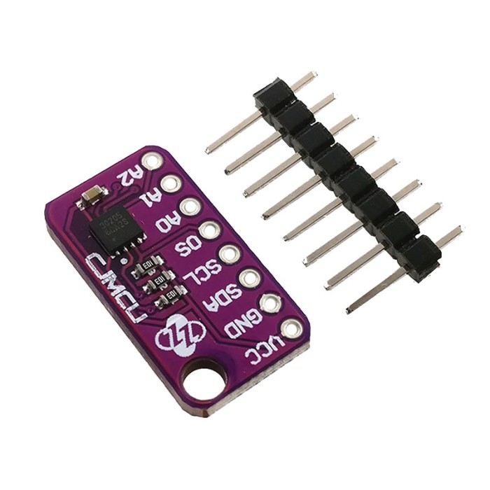
MAX30205 High Accuracy Human Body Temperature Sensor Module
$8.7500
In stock
SKU
SEN-10-116
Volume discounts:
- +25 3 % $8.4600
- +50 5 % $8.3200
- +100 7 % $8.1800
- +300 8 % $8.0300
- +500 10 % $7.8900
Ships in 2-3 business days, then:
Free delivery in 12-15 days by Tracked Economic Shipping on orders over $100.
Free delivery in 7-10 days by Express Shipping on orders over $300.
More shipping info

Shop with confidence Learn More
 Thermometer Gauge WSS-411 Previous
MAX30205 Human Body Temperature Sensor Review
The MAX30205 High Accuracy Human Body Temperature Sensor Module is a 2.7V to 3.3V I2C contact-temperature breakout for embedded health-monitoring and body-temperature prototypes. The integrated circuit provides factory-calibrated accuracy of ±0.1°C between 37°C and 39°C, but practical performance depends entirely on physical thermal coupling and PCB isolation. If your project requires an out-of-the-box certified diagnostic thermometer, non-contact measurement, or verified 5V-tolerant circuitry, this bare development board is not the right choice. For broader environmental data collection, compare dedicated temperature and humidity sensor modules.
Specifications of MAX30205 High Accuracy Human Body Temperature Sensor Module
- Accuracy: ±0.1°C (37°C to 39°C)
- Temperature Resolution: 16-bit (0.00390625°C)
- Supply Voltage: 2.7V to 3.3V
- Operating Supply Current: 600μA (typical)
- Temperature Range: 0°C to +50°C
- Communication Protocol: I2C-compatible, 2-wire serial interface
- Package: 8-pin TDFN
- Interface Functions: Open-drain overtemperature shutdown, interrupt, and comparator outputs
- Address Lines: Three address select lines, 32 available addresses
- Power-saving Modes: One-shot and shutdown modes
MAX30205 Accuracy, Resolution and Thermal Limits
A common source of confusion with digital temperature sensors is the difference between output resolution and physical measurement accuracy. The MAX30205 uses a 16-bit sigma-delta analog-to-digital converter that outputs data in increments of 0.00390625°C per least significant bit (LSB). This resolution lets firmware track micro-trends in thermal change, but it does not mean every reading is accurate to thousandths of a degree. Absolute accuracy remains bounded by the underlying sensor calibration curves.
The sensor delivers its tightest accuracy of ±0.1°C specifically across the human fever range of 37°C to 39°C. Outside this narrow window, maximum measurement tolerance widens across the operating span:
| Temperature Band | Maximum Error | Application Context |
|---|---|---|
| 37.0°C to 39.0°C | ±0.1°C | Normal to elevated human body temperature range |
| 35.8°C to 37.0°C & 39.0°C to 41.0°C | ±0.2°C | Mild hypothermia and severe fever thresholds |
| 15.0°C to 35.8°C & 41.0°C to 45.0°C | ±0.3°C | Peripheral skin exposure and elevated test surfaces |
| 0.0°C to 15.0°C & 45.0°C to 50.0°C | ±0.5°C | Near-ambient lower and upper operating limits |
The MAX30205 measures the internal silicon die temperature within its 8-pin TDFN package. For skin-contact work, the thermal mass of the PCB, copper traces, solder joints, and mounting tape all affect how quickly and accurately heat transfers from skin to the die. Ambient air currents and heat dissipated by adjacent microcontrollers can distort readings significantly. The sensor completes an electrical conversion in 44ms (50ms maximum), but true thermal equilibrium between human tissue and the sensor assembly typically requires several minutes of undisturbed direct contact.
For current-constrained projects, the IC draws approximately 600μA during active conversions. The built-in one-shot mode lets you keep the sensor in shutdown mode between readings, pulling negligible standby current until commanded to convert. If your project needs wider operating limits or combined environmental metrics rather than focused skin-temperature tracking, other sensors are more appropriate. For industrial thermal monitoring across -55°C to +125°C with hardware thermostat thresholds, examine the CJMCU LM75 Temperature Sensor. For ambient climate monitoring, the AHT10 Temperature and Humidity Sensor provides dual-variable sensing across a 1.8V to 6.0V supply. The AHT21B Temperature and Humidity Sensor operates from -40°C to +80°C with wide-supply reliability.
MAX30205 I2C, 3.3V Power and Arduino Compatibility
Operating supply limits for the MAX30205 IC are 2.7V to 3.3V. This module has no documented onboard voltage regulation or bidirectional logic-level translation. Connecting it directly to a 5V microcontroller board risks exposing the IC to overvoltage through the VCC pin or active 5V I2C bus pull-ups. With 5V microcontrollers such as a classic ATmega328P board, power the module from a clean 3.3V source and route the SDA and SCL lines through an external bidirectional logic-level converter.
The MAX30205 communicates over standard two-wire I2C at clock speeds up to 400kHz. The bare IC architecture defines three address lines (A0, A1, A2) capable of forming 32 unique slave addresses, but the address options exposed on this specific breakout depend on its traces and solder-jumper layout. In direct register communication and standard microcontroller libraries, a configuration with all address lines tied to ground uses the 8-bit write byte 0x90 (binary 10010000b). In common Arduino frameworks, this maps to the 7-bit I2C address 0x48.
| Interface Parameter | Specification Limit | Design Implication |
|---|---|---|
| Supply Voltage (VCC) | 2.7V to 3.3V | Must use a dedicated 3.3V power rail; 5V supply is not supported. |
| Logic Levels (SDA, SCL) | 3.3V compatible | Requires external level shifting when connecting to 5V controller pins. |
| I2C Bus Speed | Up to 400kHz | Compatible with Standard Mode (100kHz) and Fast Mode (400kHz). |
| Alert Pin (OS) | Open-drain output | Configurable as comparator or interrupt; requires an external pull-up resistor to function. |
| Standby Power | Shutdown mode supported | Enables periodic polling architectures for low-power battery systems. |
The OS (Overtemperature Shutdown) interface function is a configurable open-drain alert output, usable as either a comparator-style thermostat or an interrupt flag. Because it is open-drain, it cannot drive a high logic level on its own. It requires an external pull-up resistor tied to the 3.3V bus and routed to a microcontroller pin configured with an input pull-up or external hardware resistor. Shutdown mode is an internal software register state that halts active sampling, not a secondary physical output pin.
Required Hardware
- 3.3V Controller Platform: An I2C master capable of native 3.3V logic (such as an ESP32, RP2040, or STM32) or a 5V controller paired with a bidirectional level shifter.
- Connection Leads: A Breadboard Jumper Wire Kit - 140 Pieces for routing power, ground, and I2C signal lines reliably.
- Prototyping Area: An 830 points Breadboard, 5.4x16.5x0.85cm for seating breakout headers and associated pull-up resistors during verification.
- I2C Pull-Up Resistors: 4.7kΩ or 10kΩ resistors tied to 3.3V if your host controller or the breakout board does not provide bus pull-ups.
Recommended Hardware
- Bidirectional Logic Shifter: Essential when driving the sensor from 5V Arduino boards to prevent overvoltage on SDA and SCL.
- Thermal Interface Material: Thermally conductive, electrically insulating pads or tape to mechanically couple the sensor to the measurement site.
- Calibrated Reference Thermometer: A verified reference tool for calibrating your physical housing design against known standards.
Optional Hardware
- External Host Pull-Up for OS: A 10kΩ resistor to enable hardware interrupt triggering from the OS output line.
- Battery Pack and Enclosure: Low-noise battery power for wearable data-logging experiments away from mains power noise.
MAX30205 Body Temperature Measurement Limits
This module is a raw component breakout for laboratory experimentation and prototype engineering. It is not an approved medical device, diagnostic instrument, or finished clinical thermometer. The MAX30205 silicon is manufactured to meet ASTM E1112 clinical thermometry specifications when properly soldered onto a specific target PCB, but this generic development breakout carries no independent medical certification, biocompatibility ratings, or clinical calibration paperwork. It should never be relied upon for primary medical diagnosis or acute triage.
The sensor works through direct thermal conduction, not infrared radiometry. To register human temperature, its physical package must maintain direct, stable mechanical contact with the subject's skin or thermal junction. Pointing the module at an individual across open air will simply report ambient room temperature. The generic PCB also lacks the biocompatible encapsulation, sweat-proofing, and mechanical strain relief required for long-term on-body deployment. Exposing bare module traces to skin oils, perspiration, or moisture can cause signal leakage across the high-impedance I2C lines or induce corrosion.
Operating boundaries are limited to 0°C to +50°C. It cannot be deployed in sub-zero freezers, boiling liquid monitoring, environmental HVAC extremes, or industrial equipment diagnostics. Long lead wires between the module and controller also introduce parasitic bus capacitance, causing I2C communication faults. Keep leads under 30cm, or reduce bus frequency when remote placement is necessary.
If your project calls for different measurement physics or operating conditions, these alternative architectures are better suited:
- Non-Contact Body Temperature: The MLX90614 GY-906-BAA Infrared Sensor reads thermal radiation at a 2cm standoff distance, avoiding skin-contact mechanics entirely.
- Wide-Angle Remote Sensing: The MLX90614 GY-906-BCC Infrared Sensor offers 5VDC operation and a 35° field of view with integrated thermal gradient compensation.
- Waterproof and Extended-Range Sensing: For submerged monitoring, outdoor environmental deployment, or temperatures from -55°C to +125°C, the DS18B20 with 1m Waterproof Probe provides an insulated, sealed stainless-steel assembly over a 1-Wire bus.
MAX30205 Body Temperature Sensor Projects and Uses
In carefully designed prototypes, the MAX30205 serves several practical measurement roles:
- Skin-Contact Trend Loggers: By mounting the sensor against an inner wrist or chest strap with an elastic tensioner, embedded systems can track relative surface-temperature trends over time. In these designs, thermally isolating the sensor module from the main processing unit and battery prevents device self-heating from corrupting skin readings.
- Duty-Cycled Battery Monitoring Nodes: With a 3.3V microcontroller running low-power sleep modes, the MAX30205 can remain in shutdown mode, wake to take a 50ms one-shot conversion, store the reading to flash memory, and return to sleep, minimizing total power draw.
- Hardware Threshold Alerts: The OS comparator mode lets developers configure an upper trip point (such as 38.0°C) directly in the sensor registers. The open-drain output can wake a sleeping host controller or trip an indicator without requiring constant software polling across the I2C bus.
- Multi-Point Contact Arrays: Because the IC architecture supports configurable address select lines, multiple sensors can theoretically be positioned across different thermal points on a test fixture and read through a single two-wire bus, provided the breakout board exposes the address configuration pads.
Handle early bench testing on an 830 points Breadboard, 5.4x16.5x0.85cm to verify bus traffic before fabricating customized wearable housings or mechanical skin fixtures.
MAX30205 Setup and First I2C Test
Before connecting the sensor to a controller, inspect the module visually. Confirm the pin order marked on the silkscreen (typically VCC, GND, SCL, SDA, and optionally OS or address pins). If header pins are unpopulated, solder standard 0.1-inch breakaway headers for reliable electrical contact; loose push-fit connections on an I2C bus cause communication failures.
- De-energize the Host: Unplug USB and battery power from your microcontroller platform.
- Establish Connections: Using leads from a Breadboard Jumper Wire Kit - 140 Pieces, connect GND on the sensor to the microcontroller ground rail. Connect VCC to a regulated 3.3V power pin. Connect the module's SDA and SCL pins to the corresponding 3.3V-level I2C data and clock pins on your controller.
- Verify Pull-Up Voltages: Ensure your I2C lines are pulled up to 3.3V, not 5V.
- Scan the I2C Bus: Power the microcontroller and upload a standard I2C scanner sketch. In typical breakout configurations where address pins A0, A1, and A2 are tied to ground, the scanner will report an active device at 7-bit address
0x48. If the address lines are configured differently on the board, note the address detected by the scanner. - Poll the Temperature Register: Using a MAX30205-compatible library or direct I2C read commands, request a two-byte read from register
0x00(the temperature data register). The raw 16-bit signed value is multiplied by 0.00390625 to obtain the temperature in degrees Celsius. Detailed register maps and configuration bit structures can be verified in the Maxim Integrated MAX30205 Datasheet. - Observe Thermal Stabilization: At room temperature, the sensor will report the ambient temperature around the board. When placing a finger directly against the package to test response, allow 60 to 120 seconds for the reported temperature to stabilize near skin surface levels.
If the I2C scanner reports no devices found, verify that ground is shared between the sensor and controller, swap SDA and SCL in case the lines are reversed, and check that bus pull-up resistors are active. If readings return extreme or erratic values (such as 255°C or negative numbers), verify your firmware's byte-shifting order and confirm that the read transaction handles the signed 16-bit register correctly.
MAX30205 Body Temperature Sensor FAQ
Is this MAX30205 module a medical or clinical thermometer?
No. This module is an uncertified development breakout board for prototyping and laboratory experimentation. The MAX30205 IC is engineered to meet ASTM E1112 clinical thermometry specifications when implemented on a properly designed target PCB, but this raw module has not undergone clinical certification, biocompatibility testing, or medical manufacturing approvals. It must not be used for diagnostic medical decisions.
Can I connect this MAX30205 module directly to a 5V Arduino Uno?
Direct connection to a 5V Arduino Uno is not supported because the MAX30205 requires a 2.7V to 3.3V supply and does not feature documented onboard level-shifting circuitry. You can power the sensor from the Uno's 3.3V header, but you must pass the SDA and SCL lines through an external bidirectional logic-level shifter to avoid driving 5V signals into the sensor's bus pins.
Does the MAX30205 measure temperature without touching skin?
No. The MAX30205 is a contact-based temperature sensor that measures heat conducted directly into its physical package. It has no optical or infrared sensing capabilities and cannot take forehead or distance measurements. If you need non-contact thermal sensing, browse other temperature and humidity sensing approaches such as infrared thermopile modules.
Why is the stated accuracy ±0.1°C only?
The ±0.1°C factory calibration is specifically guaranteed for the narrow human core temperature band between 37°C and 39°C. Outside this interval, manufacturer tolerances widen to ±0.2°C between 35.8°C and 41°C, ±0.3°C between 15°C and 45°C, and ±0.5°C at the extremes of its 0°C to +50°C operating range.
What I2C address should I use for the MAX30205?
Most 7-bit microcontroller routines access the sensor at address 0x48 when address lines A0, A1, and A2 are tied to ground. In some lower-level datasheets and 8-bit routines, this same state is listed as 0x90 for write operations and 0x91 for read operations. Always run an I2C scanner sketch to confirm the physical address configured on your specific board.
Can several MAX30205 modules share one I2C bus?
Yes, provided each module is configured with a distinct I2C address. The underlying IC supports up to 32 discrete addresses using three address select lines, but the number of easily selectable addresses on this module depends entirely on whether address jumper pads are exposed on the breakout board.
Does this module include headers, jumper wires, a cable, or a display?
No connection cables, external displays, or diagnostic accessories are included with this bare board. Standard male breakaway headers may require soldering before installation on a breadboard.
Can the MAX30205 trigger an alarm without constant polling?
Yes. The internal OS output can be programmed via I2C to assert when temperature exceeds an upper threshold register value. Because the OS pin is an open-drain structure, it requires an external pull-up resistor to a 3.3V logic rail and a breakout pin routed to your controller's interrupt line.
How quickly does the MAX30205 update?
The ADC performs an electrical conversion in approximately 44ms (50ms maximum). Physical heat conduction from human skin through the PCB assembly to the silicon die is much slower, requiring between one and three minutes of continuous contact to achieve accurate thermal equilibrium.
Purchase Decision Summary
- Ideal for: Developers building 3.3V embedded prototypes who need high-resolution contact-temperature tracking near human fever ranges and can manage board-level thermal isolation and level shifting.
- Maybe for: Wearable research and fitness telemetry experiments where relative temperature change is tracked alongside reference equipment, provided the board is housed safely away from sweat and direct moisture.
- Avoid if: You require a certified diagnostic instrument, direct plug-and-play 5V microcontroller operation without level shifters, non-contact infrared distance measurement, waterproof immersion, or operation outside 0°C to +50°C.
Buying Checklist
- Confirm your microcontroller provides a regulated 2.7V to 3.3V supply rail.
- Procure a bidirectional logic-level shifter if pairing with a 5V controller.
- Confirm your project calls for physical contact sensing rather than infrared distance measurement.
- Verify that the 0°C to +50°C operating range covers your target environment.
- Ensure you have breadboard prototyping leads, pull-up resistors, and basic soldering tools ready for initial setup.
| Interface Type | I2C |
|---|---|
| Operating Voltage (V) | 2.7V to 3.3V |
| Operating Current (mA) | 600μA |
| Operating Temp (°C) | 0°C to +50°C |
| IP Rating | None |
| Output Type | I2C |
| Accuracy | ±0.1°C (37°C to 39°C) |
| Resolution | 16-bit |
| Measurement Range | 0°C to +50°C |
| Environmental Parameter | Temperature |
| Probe Type | Contact |
| Chipset | MAX30205 |
| Relay Output | No |
| Protocols | I2C |
| Temp Accuracy | ±0.1°C (37°C to 39°C) |
Write Your Own Review

Please complete your information below to login.
Sign In
Create New Account