

A good arduino multimeter project teaches more than simple measurement. It makes you work through voltage dividers, ADC scaling, Hall-effect current sensing, RC timing, range selection, and UI handling on a small microcontroller.
This build uses an Arduino board and an OLED display to measure four DC quantities: voltage, current, resistance, and capacitance. It is simple enough to assemble on a bench, but it still has enough moving parts that calibration and safety limits matter if you want useful readings.
Key Takeaways
- This DIY meter measures DC voltage, DC current, resistance, and capacitance.
- The voltage mode uses a resistor divider and the Arduino ADC.
- The current mode uses an ACS712 5A Hall-effect sensor module.
- The resistance mode switches between 1k, 10k, and 100k reference resistors for auto-ranging.
- The capacitance mode measures RC charge time to the 63.2% point.
- Calibration of ADC reference, resistor values, and ACS712 offset has a big effect on accuracy.
Required Materials
Arduino Multimeter Features, Ranges, and Limitations
Before you build it, decide whether this meter fits your use case. This design is meant for low-voltage DC bench work, not as a replacement for a commercial handheld meter.
| Function | Method Used | Nominal Range in This Build | Key Limitation |
|---|---|---|---|
| Voltage | Resistor divider + Arduino ADC | Up to about 15.6V in the Step 1 build | Higher voltage can damage the Arduino ADC path |
| Current | ACS712 5A Hall-effect sensor | 5A module range | Needs zero-offset calibration before use |
| Resistance | Auto-ranging divider with 1k, 10k, 100k references | Depends on selected range logic | Accuracy drops when known and unknown resistors are far apart |
| Capacitance | RC charge timing to 63.2% | Depends on charge resistor and timing window | Tradeoff between accuracy and measurable range |
| Mode | Input Path / Reference Parts | Practical Range | ADC / Timing Basis | Main Accuracy Tradeoff |
|---|---|---|---|---|
| Voltage | 10k and 4.7k divider into ADC | Up to about 15.6V in this build | ADC reading scaled from divider ratio | Divider ratio, ADC reference, and resistor tolerance |
| Current | ACS712 5A sensor module | Up to the module’s 5A range | ADC reading of sensor output, 185 mV/A | Offset drift and sensor calibration |
| Resistance | 1k, 10k, 100k switched references | Best when unknown value is near an active range | ADC reading of divider voltage | Range selection logic and resistor tolerance |
| Capacitance | 10k charge resistor, 220Ω discharge path | Set by RC time and millis() timing | Charge to ADC value 648, then solve from τ = R × C | Timing granularity and resistor choice |
What Is A Multimeter?
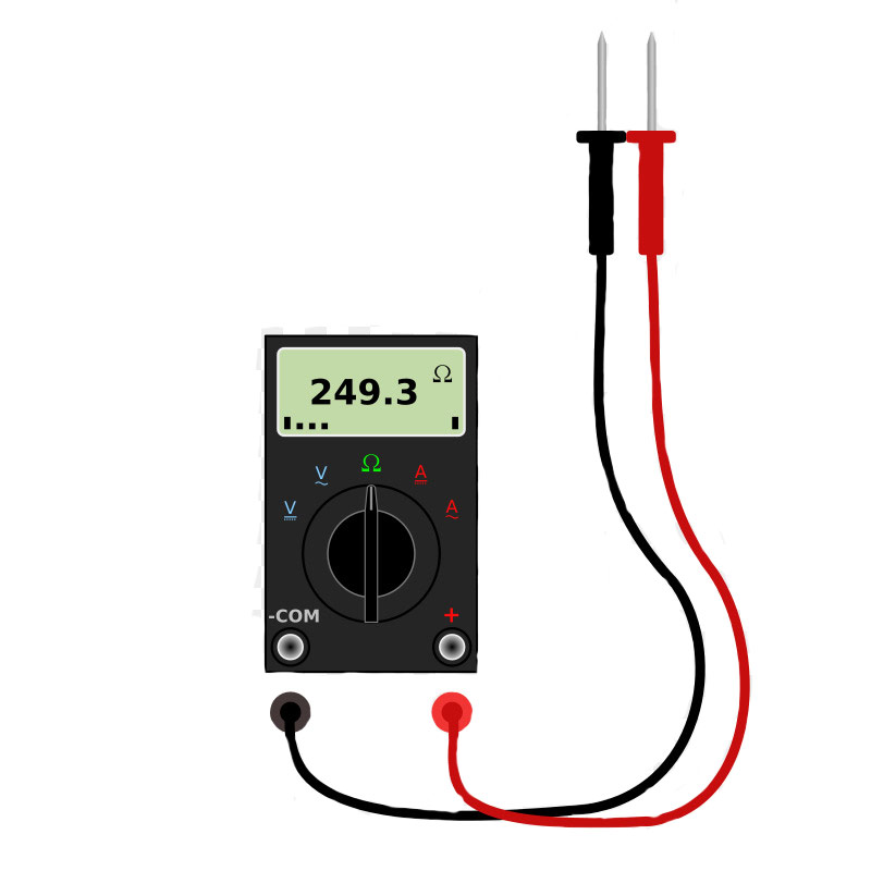
A multimeter converts electrical quantities into values you can read directly. Early instruments measured only current, but modern meters combine several measurement functions in one tool.
Multimeters are generally analog or digital. Analog meters use a pointer. Digital meters use a display and are more common in current electronics work. If you want a quick refresher on measurement basics, start with this guide on how to use a multimeter.
What Parameters Does A Multimeter Measure?
Most multimeters measure voltage, current, and resistance. Some also add capacitance, frequency, diode test, continuity, and other functions.
This Arduino-based build focuses on four measurements:
- Voltage
- Current
- Resistance
- Capacitance
Measurement Limits, Safety, and What This Meter Cannot Do
Treat this build like a low-voltage DC instrument. Its limits come from the Arduino ADC input, the resistor network used in each mode, and the ACS712 current sensor module.
The Step 1 voltmeter uses a 10k/4.7k divider and is described as measuring up to about 15.6V because the Arduino ADC input must stay within 5V. The current mode uses a 5A ACS712 module. Resistance and capacitance modes assume the part under test is isolated from external power.
Warning
A few practical boundaries matter:
- Voltage mode: keep the measured input within the divider’s intended range.
- Current mode: place the sensor in series, not in parallel.
- Resistance mode: isolate the resistor from the powered circuit.
- Capacitance mode: discharge the capacitor before connecting it for a new test.
This project is useful for learning and bench-level checks, but it is not a safety-rated replacement for a commercial meter.
Measuring the Electrical Voltage
The simplest method used here is a voltage divider. Two resistors scale the measured input down to a level the Arduino ADC can read.
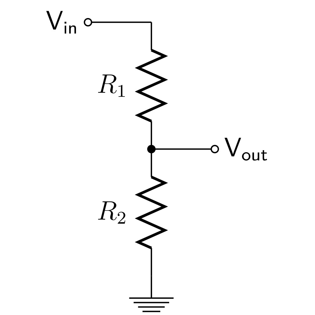
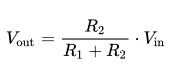
If you know R1, R2, and the ADC-measured output voltage, you can solve for the original input voltage. That is the core of the arduino voltmeter part of this build.
Measuring the Electrical Current
This build measures current with an ACS712 Hall-effect current sensor module. The sensor converts current into a proportional output voltage, which the Arduino reads through its ADC.
The original project uses the 5A version and states a sensitivity of 185 millivolts per amp.
Measuring the Resistance
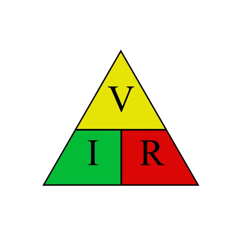
Another current-measurement method is a shunt resistor with Ohm’s law, but that is not the method used in this build.
Measuring the Resistance
The project uses the same divider idea for resistance, but here the unknown resistor becomes the value to solve for. The code switches between known reference resistors to improve accuracy across a wider span.
The code averages 20 ADC samples, converts that average to voltage, and then scales it back up through the divider ratio.
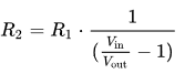
When the known and unknown resistor values are too far apart, accuracy gets worse. That is why the design uses 1k, 10k, and 100k reference values instead of a single resistor.
Measuring the Capacitance
Capacitance mode uses the RC charging rule. The Arduino starts charging the capacitor, watches the ADC reading, and records the time until the capacitor reaches 63.2% of the final voltage.
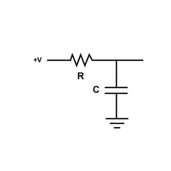
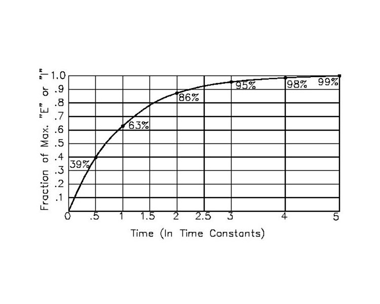
The time constant is:
τ^(second)=R×C
So if you know the resistor value and measure the charge time to 63.2%, you can calculate capacitance.
Resistor Selection Criteria
Resistor choice directly affects range, loading, and accuracy.
For voltage mode, the 10k and 4.7k divider sets the measurement range. The original build states that this combination allows measurement up to about 15.6V while keeping the Arduino ADC input within 5V. If you change the divider ratio, you change the usable range and the scaling in code.
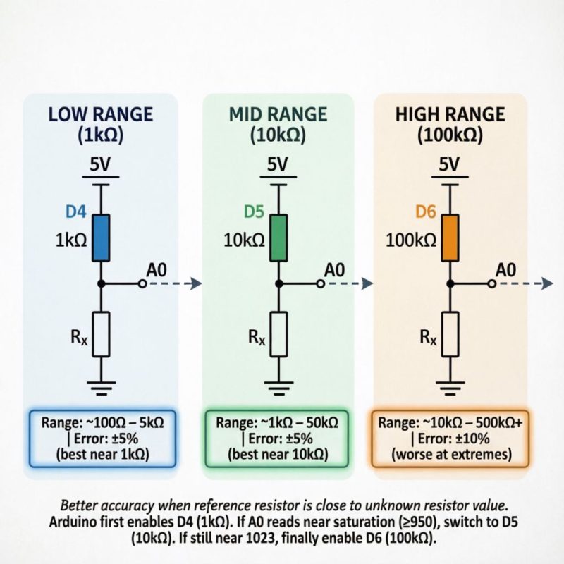
For resistance mode, the 1k, 10k, and 100k references create three effective ranges. Results are better when the unknown resistor is reasonably close to the active reference resistor.
Resistor tolerance matters in both cases. If the actual resistor values differ from the nominal values used in code, every reading shifts. Measuring your real resistor values first and plugging those values into the sketch is one of the easiest ways to improve accuracy.
Making a Digital Multimeter Using Arduino
This arduino multimeter project is built in five parts:
- Voltmeter
- Ammeter
- Ohmmeter
- Capacitance meter
- OLED menu and integration
Build and test each mode separately before loading the combined sketch.
Step 1: Making the Voltmeter
This stage builds the Arduino voltmeter path using a resistor divider and the Arduino ADC.
Circuit
The original circuit uses 10k and 4.7k resistors for the divider.
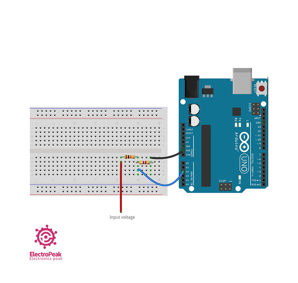
The voltmeter must connect in parallel with the section whose voltage you want to measure.
The code averages 20 ADC samples, converts that average to voltage, and then scales it back up through the divider ratio.
Tip
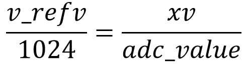
A practical detail: the Arduino 10-bit ADC outputs codes 0 through 1023, and the AVR datasheet transfer function uses /1024 because each code represents a voltage bin of width Vref / 1024. Some guides use /1023.0 to map the top code exactly to Vref; that is a common approximation, but /1024 matches the datasheet convention. The difference is small (about 0.1%), so either way, calibrate against a known meter rather than relying on the divisor alone.
Code
					/*
  Voltmeter with Arduino
   modified on 21 Jul 2019
  by Saeed Hosseini @ Electropeak
  Home
*/
const int VoltMeter = A2;
float V = 0.00;
void calculate_voltage()
{
    float R1 = 10000.00;
    float R2 = 4700.00;
    float v_ref = 5.00;
    float resistor_ratio = 0.00;
    float adc_value = 0.00;
    float voltage = 0.00;
    resistor_ratio = (R2 / (R1 + R2));
    for (int i = 0; i < 20; i++)
    {
        adc_value = adc_value + analogRead(VoltMeter);
        delay(3);
    }
    adc_value = adc_value / 20;
    voltage = ((adc_value * v_ref) / 1024);
    V = voltage / resistor_ratio;
}
void setup()
{
    Serial.begin(9600);
}
void loop()
{
    calculate_voltage();
    Serial.print(V);
    Serial.println(" v");
    delay(2000);
}
Step 2: Making the Ammeter
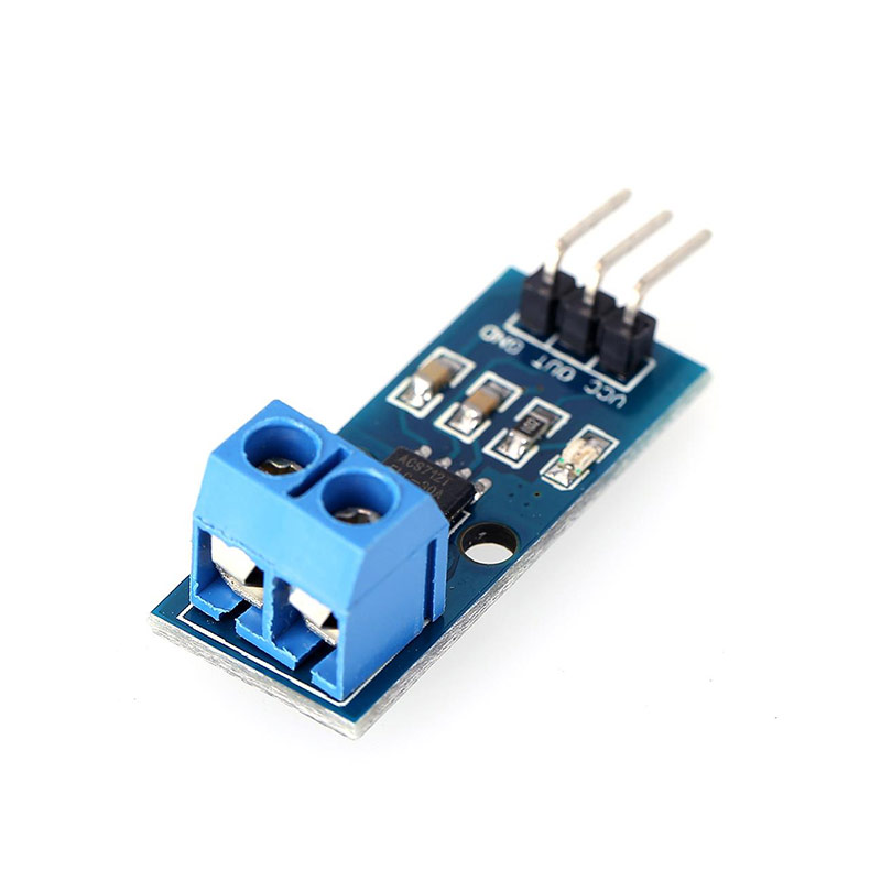
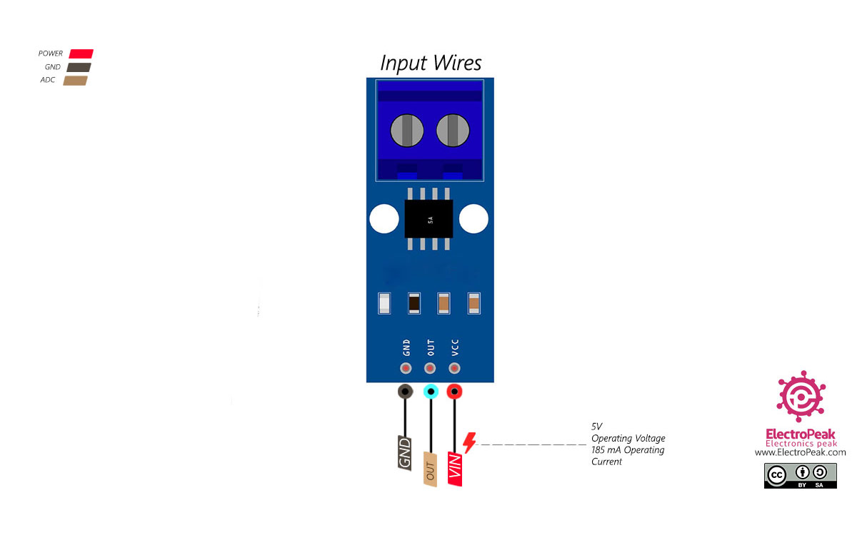
This stage uses the ACS712 5A current sensor module to read current without putting a shunt resistor directly into the Arduino analog input path. If you need the module itself, the build uses an ACS712 current sensor module.
The sensor uses the Hall effect and outputs a voltage proportional to current. In the original project, the 5A version is used and the sensitivity is 185 mV/A.
Circuit
Connect the circuit as shown:
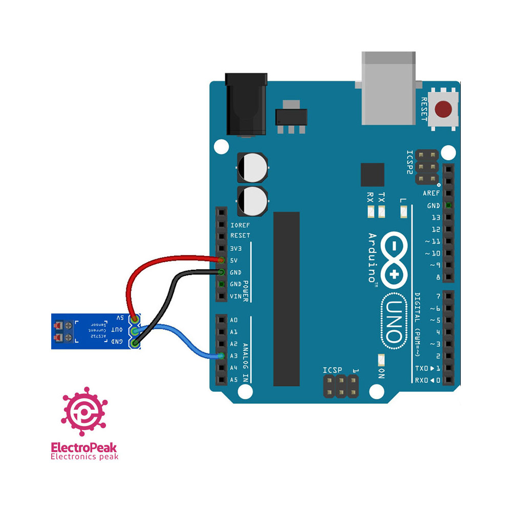
The ammeter must be placed in series with the current path.
Warning
Wire the ACS712 in series with the load, verify the current path orientation before power-up, and stay within the module’s 5A range. Wiring it in parallel or bypassing the intended sensor path can give false readings or damage the build.
Code
					/*
  Ammeter with Arduino
  modified on 21 Jul 2019
  by Saeed Hosseini @ Electropeak
  Home
*/
const int Ammeter = A2;
float I = 0.00;
void calculate_current() {
  int sensitivity = 185;
  int adc_value = 0;
  float v_ref = 4.94;
  float voltage = 0.00;
  float pure_voltage = 0.00;
  float offset_voltage = 2.47;
  for (int i = 0; i < 40 ; i++)
  {
    adc_value = adc_value + analogRead(Ammeter);
    delay(2);
  }
  adc_value = adc_value / 40;
  voltage = ((adc_value * v_ref) / 1024);
  pure_voltage = voltage - offset_voltage;
 // if(pure_voltage > 0.001) pure_voltage = 0.00;
  pure_voltage = pure_voltage * 1000;
  I = pure_voltage / sensitivity;
  Serial.println(String("ADC = ") + adc_value );
  Serial.println(String("V = ") + voltage + "v");
  Serial.println(String("Pure = ") + pure_voltage + "mv");
  Serial.println(String("I = ") + I + "A");
}
void setup() {

  Serial.begin(9600);
}
void loop() {
  calculate_current();
  //Serial.println(String("I = ") + I + " mA");
  delay(2000);
}
offset_voltage = 2.47, but this is only the value measured from onespecific module. The ACS712 quiescent output is nominally Vcc/2 (~2.5V), yet real modules vary with
supply voltage and manufacturing tolerance. Before trusting current readings, power the module with no load,
measure its output pin voltage with a known multimeter, and replace
offset_voltage with your measured value.Step 3: Creating the Ohmmeter
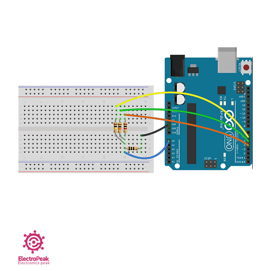
The ohmmeter uses auto-ranging by switching between 1k, 10k, and 100k reference resistors. That keeps the known resistor
closer to the unknown resistor and improves the result.
Circuit
Code
					/*
  Ohmmeter with Arduino - Automatic range
  modified on 21 Jul 2019
  by Saeed Hosseini @ Electropeak
  Home
*/
const int OhmMeter = A0;
const int R3 = 6;
const int R2 = 5;
const int R1 = 4;
float R = 0.00;
void calculate_resistor()
{
    float v_ref = 4.94;
    float r1 = 0.00;
    float r_ref1 = 1000.00;
    float adc_value1 = 0.00;
    float voltage1 = 0.00;
    float r2 = 0.00;
    float r_ref2 = 10000.00;
    float adc_value2 = 0.00;
    float voltage2 = 0.00;
    float r3 = 0.00;
    float r_ref3 = 100000.00;
    float adc_value3 = 0.00;
    float voltage3 = 0.00;
    pinMode(R1, OUTPUT);
    pinMode(R2, INPUT);
    pinMode(R3, INPUT);
    pinMode(OhmMeter, INPUT);
    digitalWrite(R1, HIGH);
    for (int i = 0; i < 20; i++)
    {
        adc_value1 = adc_value1 + analogRead(OhmMeter);
        delay(3);
    }

    adc_value1 = adc_value1 / 20;

    if (adc_value1 < 1022.90)
    {
        voltage1 = ((adc_value1 * v_ref) / 1024);
        r1 = (voltage1 * r_ref1) / (v_ref - voltage1);
    }
    pinMode(R1, INPUT);
    pinMode(R2, OUTPUT);
    pinMode(R3, INPUT);
    digitalWrite(R2, HIGH);
    for (int i = 0; i < 20; i++)
    {
        adc_value2 = adc_value2 + analogRead(OhmMeter);
        delay(3);
    }
    adc_value2 = adc_value2 / 20;
    if (adc_value2 < 1022.90)
    {
        voltage2 = ((adc_value2 * v_ref) / 1024);

        r2 = (voltage2 * r_ref2) / (v_ref - voltage2);
    }
    pinMode(R1, INPUT);
    pinMode(R2, INPUT);
    pinMode(R3, OUTPUT);
    digitalWrite(R3, HIGH);
    for (int i = 0; i < 20; i++)
    {
        adc_value3 = adc_value3 + analogRead(OhmMeter);
        delay(3);
    }
    adc_value3 = adc_value3 / 20;
    if (adc_value3 < 1022.90)
    {
        voltage3 = ((adc_value3 * v_ref) / 1024);
        r3 = (voltage3 * r_ref3) / (v_ref - voltage3);
    }
    r1 = r1 / 1000;

    r2 = r2 / 1000;

    r3 = r3 / 1000;
    if (r1 < 2 && r2 < 101 && r3 < 1001)
        R = r1 * 1000;
    else if (r1 > 2 && r2 < 101 && r3 < 1001)
        R = r2;
    else if (r1 > 2 && r2 > 101 && r3 < 2000)
        R = r3;
    else
        R = 0.00;
    Serial.print("R = ");

    Serial.println(R, 2);
}
void setup()
{

    Serial.begin(9600);
}
void loop()
{
    calculate_resistor();
    Serial.println("_________________________________________");

    delay(2500);
}
The switching logic turns only one reference path on at a time. The other range pins are set as inputs so they are effectively disconnected.
Warning
The original code had an r3 calculation bug that used voltage2 in the denominator. It has been corrected here to use voltage3. Verify the mode against known resistors after upload.
That warning applies to both the standalone ohmmeter code and the final combined sketch, because the same code pattern appears there.
Step 4: Building the Capacitance Meter
This mode measures charge time through a known resistor, then discharges the capacitor so you can test the next part.
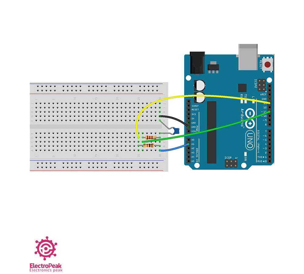
Circuit
The original circuit uses a 10k resistor to charge the capacitor and a 220Ω resistor for discharge.
Code
					/*
  Capacitance meter with Arduino
  modified on 21 Jul 2019
  by Saeed Hosseini @ Electropeak
  base on: https://www.arduino.cc/en/Tutorial/CapacitanceMeter
  Home
*/
const int CapacitancMeter = A1;
const int ChargePin = 13;
const int DischargePin = 11;
float C = 0.00;
void calculate_capacitance()
{
    unsigned long start_time;
    unsigned long elapsed_time;
    float microFarads;
    float nanoFarads;
    float r_ref = 10000.00;
    digitalWrite(ChargePin, HIGH);
    start_time = millis();
    while (analogRead(CapacitancMeter) < 648)
    {
    }
    elapsed_time = millis() - start_time;
    microFarads = ((float)elapsed_time / r_ref) * 1000;
    if (microFarads > 1)
    {
        C = microFarads;
    }

    else
    {
        nanoFarads = microFarads * 1000.0;
        C = nanoFarads;
    }
    digitalWrite(ChargePin, LOW);
    pinMode(DischargePin, OUTPUT);
    digitalWrite(DischargePin, LOW);
    while (analogRead(CapacitancMeter) > 0)
    {
    }
    pinMode(DischargePin, INPUT);
}

void setup()
{
    Serial.begin(9600);
    pinMode(ChargePin, OUTPUT);

    digitalWrite(ChargePin, LOW);
}
void loop()
{
    calculate_capacitance();
    Serial.println(C);

    delay(2000);
}
The measurement flow is:
- Start charging the capacitor
- Record the start time with
millis() - Wait until the ADC reaches 648, which represents 63.2%
- Calculate capacitance from time and resistance
- Discharge the capacitor fully
If you increase the charge resistor value, the timing gets longer and small capacitance measurements can improve. The tradeoff is a reduced measurable range and slower readings.
Step 5: Wrapping it Up And Adding a Display
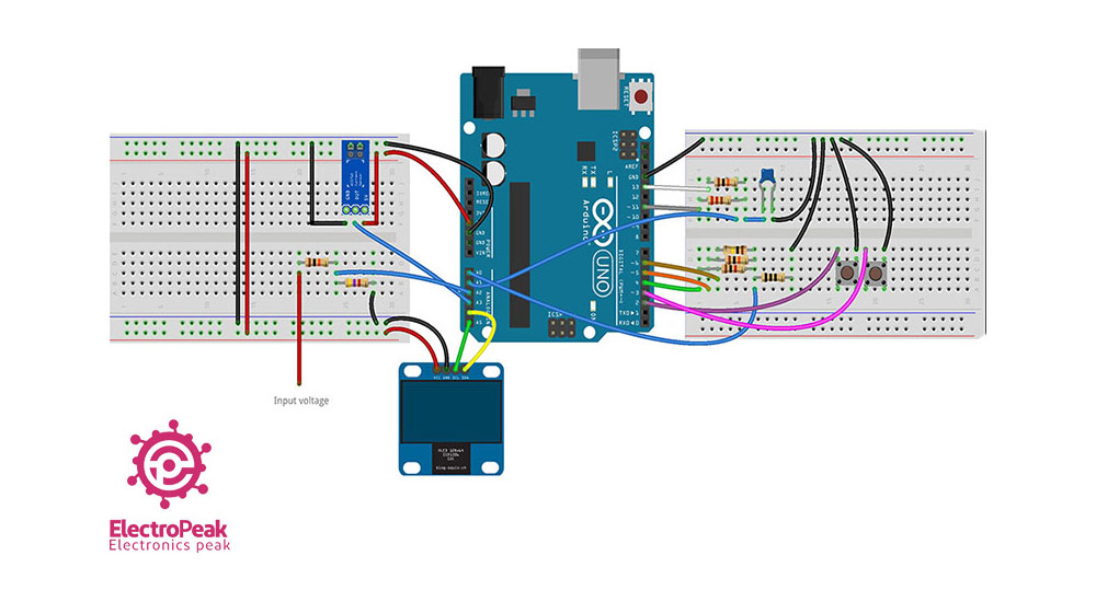
After each measurement block works on its own, combine them into a single diy multimeter with an OLED menu and two buttons for navigation.
Circuit
Code
					/*
  Digital Multimeter with Arduino and OLED
  modified on 21 Jul 2019
  by Saeed Hosseini @ Electropeak
  Home
*/
#include <Wire.h>
#include <Adafruit_GFX.h>
#include <Adafruit_SSD1306.h>
#include "logo.h"
#define SCREEN_WIDTH 128
#define SCREEN_HEIGHT 32
#define OLED_RESET -1
Adafruit_SSD1306 display(SCREEN_WIDTH, SCREEN_HEIGHT, &Wire, OLED_RESET);
const int select_button = 2;
const int right_button = 3;
const int OhmMeter = A0;
const int CapacitanceMeter = A1;
const int VoltMeter = A2;
const int Ammeter = A3;
const int R3 = 6;
const int R2 = 5;
const int R1 = 4;
const int ChargePin = 13;
const int DischargePin = 11;
boolean is_select = false;
int navigator = 0;
int flag = 0;
float R = 0.00;
float V = 0.00;
float I = 0.00;
float C = 0.00;
boolean nano = false;
boolean kilo = false;
boolean mili = false;
void OLED_init()
{
    if (!display.begin(SSD1306_SWITCHCAPVCC, 0x3C))
    {
        Serial.println(F("SSD1306 allocation failed"));
        for (;;)
            ;
    }
    display.clearDisplay();
    display_logo(15, 3, Electropeak, F_LOGO_WIDTH, F_LOGO_HEIGHT);
    display.display();
    delay(2000);
    display_clear();
}
void display_clear()
{
    display.clearDisplay();
    display.display();
}
void display_logo(int x, int y, const uint8_t *bitmap, int w, int h)
{
    display.drawBitmap(x, y, bitmap, w, h, WHITE);
}
void display_text(int sz, int x, int y, String str)
{
    display.setTextSize(sz);
    display.setTextColor(WHITE);
    display.setCursor(x, y);
    display.println(str);
}
void display_number(int sz, int x, int y, double num)
{
    display.setTextSize(sz);
    display.setTextColor(WHITE);
    display.setCursor(x, y);
    display.println(num);
}
void calculate_resistor()
{
    float v_ref = 4.94;
    float r1 = 0.00;
    float r_ref1 = 1000.00;
    float adc_value1 = 0.00;
    float voltage1 = 0.00;
    float r2 = 0.00;
    float r_ref2 = 10000.00;
    float adc_value2 = 0.00;
    float voltage2 = 0.00;
    float r3 = 0.00;
    float r_ref3 = 100000.00;
    float adc_value3 = 0.00;
    float voltage3 = 0.00;
    pinMode(R1, OUTPUT);
    pinMode(R2, INPUT);
    pinMode(R3, INPUT);
    digitalWrite(R1, HIGH);
    for (int i = 0; i < 20; i++)
    {

        adc_value1 = adc_value1 + analogRead(OhmMeter);
        delay(3);
    }
    adc_value1 = adc_value1 / 20;

    if (adc_value1 < 1022.90)

    {

        voltage1 = ((adc_value1 * v_ref) / 1024);

        r1 = (voltage1 * r_ref1) / (v_ref - voltage1);
    }

    pinMode(R1, INPUT);

    pinMode(R2, OUTPUT);

    pinMode(R3, INPUT);

    digitalWrite(R2, HIGH);

    for (int i = 0; i < 20; i++)

    {

        adc_value2 = adc_value2 + analogRead(OhmMeter);

        delay(3);
    }

    adc_value2 = adc_value2 / 20;

    if (adc_value2 < 1022.90)

    {

        voltage2 = ((adc_value2 * v_ref) / 1024);

        r2 = (voltage2 * r_ref2) / (v_ref - voltage2);
    }

    pinMode(R1, INPUT);

    pinMode(R2, INPUT);

    pinMode(R3, OUTPUT);

    digitalWrite(R3, HIGH);

    for (int i = 0; i < 20; i++)

    {

        adc_value3 = adc_value3 + analogRead(OhmMeter);

        delay(3);
    }

    adc_value3 = adc_value3 / 20;

    if (adc_value3 < 1022.90)

    {

        voltage3 = ((adc_value3 * v_ref) / 1024);

        r3 = (voltage3 * r_ref3) / (v_ref - voltage3);
    }

    r1 = r1 / 1000;

    r2 = r2 / 1000;

    r3 = r3 / 1000;

    if (r1 < 2 && r2 < 101 && r3 < 1001)
        R = r1 * 1000;

    else if (r1 > 2 && r2 < 101 && r3 < 1001)
        R = r2;

    else if (r1 > 2 && r2 > 101 && r3 < 2000)
        R = r3;

    else
        R = 0.00;

    if (R < 1)

    {

        R = R * 1000;

        kilo = false;
    }

    else

    {

        kilo = true;
    }
}

void calculate_capacitance()
{

    unsigned long start_time;

    unsigned long elapsed_time;

    float microFarads;

    float nanoFarads;

    float r_ref = 10000.00;

    digitalWrite(ChargePin, HIGH);

    start_time = millis();

    while (analogRead(CapacitanceMeter) < 648)
    {
    }

    elapsed_time = millis() - start_time;

    microFarads = ((float)elapsed_time / r_ref) * 1000;

    if (microFarads > 1)

    {

        C = microFarads;

        nano = false;
    }

    else

    {

        nanoFarads = microFarads * 1000.0;

        C = nanoFarads;

        nano = true;
    }

    digitalWrite(ChargePin, LOW);

    pinMode(DischargePin, OUTPUT);

    digitalWrite(DischargePin, LOW);

    while (analogRead(CapacitanceMeter) > 0)
    {
    }

    pinMode(DischargePin, INPUT);
}

void calculate_voltage()
{

    float R1 = 10000.00;

    float R2 = 4700.00;

    float v_ref = 5.00;

    float resistor_ratio = 0.00;

    float adc_value = 0.00;

    float voltage = 0.00;

    resistor_ratio = (R2 / (R1 + R2));

    for (int i = 0; i < 20; i++)

    {

        adc_value = adc_value + analogRead(VoltMeter);

        delay(3);
    }

    adc_value = adc_value / 20;

    voltage = ((adc_value * v_ref) / 1024);

    V = voltage / resistor_ratio;
}

void calculate_current()
{

    int sensitivity = 185;

    int adc_value = 0;

    float v_ref = 4.94;

    float voltage = 0.00;

    float pure_voltage = 0.00;

    float offset_voltage = 2.47;

    for (int i = 0; i < 40; i++)

    {

        adc_value = adc_value + analogRead(Ammeter);

        delay(2);
    }

    adc_value = adc_value / 40;

    voltage = ((adc_value * v_ref) / 1024);

    pure_voltage = voltage - offset_voltage;

    pure_voltage = pure_voltage * 1000;

    I = pure_voltage / sensitivity;

    if (I < 1)

    {

        I = I * 1000;

        mili = true;
    }

    else

    {

        mili = false;
    }
}
void setup()
{

    Serial.begin(9600);

    OLED_init();

    pinMode(right_button, INPUT_PULLUP);

    pinMode(select_button, INPUT_PULLUP);

    pinMode(ChargePin, OUTPUT);

    digitalWrite(ChargePin, LOW);
}

void loop()
{

    if (digitalRead(right_button) == 0)
    {

        navigator++;

        while (digitalRead(right_button) == 0)
            ;

        delay(5);

        if (navigator > 3)
            navigator = 0;

        Serial.println(navigator);
    }

    if (digitalRead(select_button) == 0)

    {

        is_select = true;

        while (digitalRead(select_button) == 0)
            ;
    }

    if (navigator == 0)

    {

        display.clearDisplay();

        display_logo(0, 0, RightArrow, F_LOGO_WIDTH, F_LOGO_HEIGHT);

        display_text(2, 17, 8, "Resistor");

        display.display();

        while (is_select)

        {

            display.clearDisplay();

            display_text(1, 0, 0, "Resistor");

            display_text(2, 12, 8, "R=");

            display_number(2, 42, 8, R);

            if (kilo)
                display_text(1, 115, 15, "k");

            display.display();

            calculate_resistor();

            if (digitalRead(select_button) == 0)

            {

                is_select = false;

                while (digitalRead(select_button) == 0)
                    ;
            }
        }
    }

    if (navigator == 1)

    {

        display.clearDisplay();

        display_logo(0, 0, BothArrow, F_LOGO_WIDTH, F_LOGO_HEIGHT);

        display_text(2, 17, 8, "Voltage");

        display.display();

        while (is_select)

        {

            display.clearDisplay();

            display_text(1, 0, 0, "Voltage");

            display_text(2, 12, 8, "V=");

            display_number(2, 42, 8, V);

            display_text(1, 115, 15, "v");

            display.display();

            calculate_voltage();

            if (digitalRead(select_button) == 0)

            {

                is_select = false;

                while (digitalRead(select_button) == 0)
                    ;
            }
        }
    }

    if (navigator == 2)

    {

        display.clearDisplay();

        display_logo(0, 0, BothArrow, F_LOGO_WIDTH, F_LOGO_HEIGHT);

        display_text(2, 17, 8, "Current");

        display.display();

        while (is_select)

        {

            display.clearDisplay();

            display_text(1, 0, 0, "Current");

            display_text(2, 12, 8, "I=");

            display_number(2, 42, 8, I);

            if (mili)
                display_text(1, 115, 15, "mA");

            if (!mili)
                display_text(1, 115, 15, "A");

            display.display();

            calculate_current();

            if (digitalRead(select_button) == 0)

            {

                is_select = false;

                while (digitalRead(select_button) == 0)
                    ;
            }
        }
    }

    if (navigator == 3)

    {

        display.clearDisplay();

        display_logo(0, 0, LeftArrow, F_LOGO_WIDTH, F_LOGO_HEIGHT);

        display_text(2, 12, 8, "Capacitor");

        display.display();

        while (is_select)

        {

            display.clearDisplay();

            display_text(1, 0, 0, "Capacitor");

            display_text(2, 12, 8, "C=");

            display_number(2, 42, 8, C);

            if (nano)
                display_text(1, 115, 22, "nF");

            if (!nano)
                display_text(1, 115, 22, "uF");

            display.display();

            calculate_capacitance();

            if (digitalRead(select_button) == 0)

            {

                is_select = false;

                while (digitalRead(select_button) == 0)
                    ;
            }
        }
    }
}

Info
logo.h and the OLED libraries must be present beside the final sketch for compilation to succeed. The OLED code also expects an SSD1306 display at I2C address 0x3C.
If you want to simplify sourcing, this build pairs naturally with an Arduino Uno R3 and a 0.96 inch I2C OLED display module.
How the Circuit Works
Once the separate modes are combined, it helps to think of the system as four measurement blocks sharing one controller and one display.
- A0: ohmmeter input
- A1: capacitance meter input
- A2: voltmeter input
- A3: ACS712 current sensor input
- D4, D5, D6: ohmmeter range switching
- D11: capacitor discharge control
- D13: capacitor charge control
- D2 and D3: menu buttons
- I2C OLED: display output
The Arduino reads one measurement path at a time, converts it into engineering units, and updates the OLED menu. The two buttons handle mode selection without physically changing the underlying measurement circuits.
Libraries and Code Assets
The final sketch depends on standard Arduino libraries plus one extra local file
| Dependency / File | Purpose | Required For |
|---|---|---|
Wire.h |
I2C communication | OLED display |
Adafruit_GFX.h |
Graphics primitives and text | OLED display |
Adafruit_SSD1306.h |
SSD1306 driver | OLED display |
logo.h |
Bitmap/logo assets used by the menu | Final combined sketch |
Install the OLED libraries before uploading the final sketch. Keep logo.h in the same folder as the main .ino file.
Calibration and Accuracy
Build it first. Calibrate it second. If you skip calibration, you can still get numbers, but they may not be useful numbers.
Start with the values that affect every mode:
- The actual Arduino supply or ADC reference used in calculations
- The real resistance values of the divider and range resistors
- The ACS712 no-load offset voltage
- Comparison against a known meter on real test points
Competitor builds report that DIY Arduino meters can need calibration and may differ from a conventional multimeter by noticeable amounts. One example reported about 200 mV error before adjustment. Actual accuracy after calibration depends on component tolerance, ADC reference stability, and how carefully you calibrate each mode, so treat any published DIY accuracy figure as a rough benchmark rather than a guaranteed specification.
Tip
Measure the actual 5V reference and the real resistor values before editing the code. Those two checks improve voltage, resistance, current scaling, and capacitance results faster than tweaking display formatting.
A good workflow is:
- Measure the Arduino 5V rail with a known multimeter.
- Measure the actual 10k, 4.7k, 1k, 10k, and 100k resistors.
- Replace nominal values in code with measured values where practical.
- Calibrate the ACS712 offset with zero current.
- Compare each mode against a known reference and adjust if needed.
| Item to Calibrate | What to Compare Against | What to Adjust / Verify | When to Recheck |
|---|---|---|---|
| ADC reference / supply voltage | Known multimeter on Arduino 5V rail | v_ref used in code |
After power-source changes |
| Voltage divider resistors | Measured resistor values | R1, R2, divider ratio |
After resistor changes |
| ACS712 zero offset | Sensor output with no load | offset_voltage |
At first setup and if readings drift |
| Ohmmeter ranges | Known resistors near 1k, 10k, 100k | Range logic and reference values | After code edits |
| Capacitance timing | Known capacitor values | Charge resistor assumption and timing behavior | After changing resistor or timing method |
Testing and Validation
Test each mode with a known reference before you trust the integrated meter.
For voltage mode, use a battery or a stable DC supply. For current mode, run a known load through the ACS712 and compare the result to a reference meter. For resistance mode, test parts with known values near each auto-range boundary. For capacitance mode, test known capacitors and confirm the discharge step does not hang.
| Mode | Known Test Reference | Expected Behavior | If Reading Is Off |
|---|---|---|---|
| Voltage | Known DC battery or bench supply | Reading tracks the reference meter closely | Recheck divider values and v_ref |
| Current | Known load current through ACS712 | Zero-current offset is near calibrated center; loaded reading scales correctly | Recalibrate offset and verify series wiring |
| Resistance | Known 1k, 10k, 100k resistors | Meter selects sensible range and returns close value | Check range logic and r3 calculation path |
| Capacitance | Known capacitor values | Reading changes with part value and completes discharge cycle | Check discharge path and charge resistor assumptions |
Troubleshooting
Most failures in this kind of build come from three places: wiring mistakes, calibration assumptions, or code dependencies that were not installed.
If the display stays blank, start with I2C wiring and the OLED address. If readings jump around with nothing connected, assume the analog input is floating until proven otherwise. If the buttons act erratically, verify INPUT_PULLUP behavior and wiring to ground.
Info
Floating inputs, wrong OLED I2C address, and button wiring are the first checks for unstable or nonresponsive behavior.
| Symptom | Likely Cause | Check / Fix |
|---|---|---|
| Voltage reading appears with nothing connected | Floating analog input | Confirm input wiring and ignore small no-load values; some builds clamp low readings in code |
| OLED does not display anything | Wrong wiring or wrong I2C address | Check I2C lines and verify address 0x3C |
| Current reads non-zero at no load | ACS712 offset not calibrated | Measure sensor output with no load and update offset_voltage |
| Resistance readings are obviously wrong | Range logic or r3 code path issue |
Review the third-range calculation and test known resistors |
| Capacitance reading stalls during discharge | Capacitor not discharging cleanly | Check discharge resistor path and test with a discharged capacitor |
| Buttons skip or repeat modes | Wiring or debounce issue | Recheck button wiring and press handling logic |

Comments (71)
Hello. thank you for this Article. it will surely be a great help in building our own multimeter project. I hope you’ll response in my question while building this kind of project. Thanks again!
Hi. We are very glad to hear this article was useful for you.
hi there, just wanna ask some question. how can i combine all the codes?
Hi.
Actually you don’t need to compile all the codes to make the digital multimeter. Separate parts of the digital multimeter are explained in steps 1 to 4. And in step 5, all previous steps are wrapped up in a single circuit and code. So if your question is how you can make a complete digital multimeter -and not just an Ohmmeter or Ammeter-, you can do that by just following the code and circuit of the step 5.
hehe you’re right, its in step 5. thanks a lot.
what should be the right thing to do with the logo.h file? i’ve copied it to the folder where my code is located but it keeps showing an error “logo.h: no such file or directory”.
You should copy it to the folder where your .ino file is located, meaning that logo.h and your .ino file must be in the same folder. In that way when you open the .ino file, logo.h will also appear in a tab next to it. And then there shouldn’t be any problem.
thank you. it finally works! thanks for this article!
Where to connect the inputs for resistance and capacitance?
For measuring the resistance, connect the resistor to the A0 and GND pins of your Arduino Board. And for capacitance, you need to connect the capacitor to pins A1 and GND.
excuse me guys but i dont know how to measure the current?? so can you tell me where to connect the inputs of th curreny?
Hi,
To measure the current, you need to use the AC712 sensor. It is well explained in the “Step 2: Making the Ammeter” section. This sensor has 3 pins, 2 for the power supply -GND and VCC- and the other one “OUT” which is the output pin of the sensor and needs to be connected to an analog pin of Arduino Board -A3 in our case-. Other necessary notes are also included in article.
Hello,
I’m trying assembly this circuit on tinkercad, but I can’t find the part (0.96″ I2C OLED Display Module)
The picture that you shared on step 5 is about tinkercad or did you use another software?
Can you please help me?
Hello Luis,
The picture in step 5 is actually made using a combination of the fritzing and photoshop software programs just to show how the wiring should be. And If you want to use Tinkercad for modelling the circuit, the following link might be helpful. “https://www.tinkercad.com/things/2EKXoCr8iki-096-128×64-oled-display”
Electropeak in making the capacitance
What is the name of the Blue component used with the resistors
That’s the capacitor that we want to measure the value of.
What if I want to add a chargeable battery to the circuit how can I go about it.
Secondly please where would my red and black probes be fixed on the board.
To add a chargeable battery -or any other type of battery-, you can just connect the positive terminal of the battery to the VIN pin and the negative terminal to the GND pin of the Arduino board. And you don’t need to make any other changes to the rest of the circuit.
And about the probes, the black one can be fixed at the GND pin. But where the red one should be fixed at depends on what electrical component you want to measure the value of. For example, to measure the value of a resistor or a capacitor, you should fix the red probe at A0 or A1 pin of your Arduino board respectively.
Thank you very much
This website is very helpful
but can I ask please
What if i did not get the AC712 5A Current Sensor is there any alternatives
You’re quite welcome. So glad the tutorials have been useful for you.
About the ACS712 current sensor, you can replace that with any other current sensor that has an analog output voltage ranging 0 to 5 volts. Then you need to change the code according to the current to voltage formula of the sensor you’re using.
Thank you for this. I’m currently doing a similar project
Right now I’m searching for the best way to adapt main voltage (220 VAC) signal into an analog input that doesn’t fry up my arduino. A voltage divider is out of question and I don’t seem to find a suitable transformer for the job of just measuring.. Any suggestions?
Hello.
You’re welcome.
There are actually a handful of modules that can convert high voltage AC to a DC voltage that can be read by any of your Arduino analog pins. ZMPT101B voltage sensor is one of these modules. You can also find a good tutorial of this sensor in our website. Here’s the link: “https://electropeak.com/learn/interfacing-zmpt101b-voltage-sensor-with-arduino/”
could not convert display.Adafruit_SSD1306 from void to bool
That is what my code( in the Arduino ide) is saying
Any help please ?????
Which line of the code is the error for? There might also have been some mistakes made while copying the code. So, please double check it and make sure that nothing has gone wrong in the process of copying the code and taking it to your Aduino IDE. Then, if the error still persisted and didn’t go away, say which line of the code exactly the error is about.
Electropeak thank you very much I am done with the project but I am having some incorrect readings, the resistor is not measuring and before I test for anything the multimeter just keep reading Like when it is supposed to be 0.00 it would keep reading randomly. Any help please
Your problem can be actually related to the tolerance of the components in your circuit. And generally, a little inaccuracy is acceptable.
Hi,
Do you have an idea how to protect the meter be mistested or misseted, say use a R gear to measure a Voltage by mistake?
Thanks
Adam
Hi,
Unfortunately, I couldn’t fully understand your point. But if you mean how you could calibrate the multimeter so that the voltage is never measured wrongly, you can do as following: You can add this capability to your multimeter by replacing the R2 resistor in the “Measuring the Electrical Voltage” circuit with a multi-turn potentiometer. So, this way, whenever you feel your multimeter is out of calibration, you can adjust the value of the resistor and calibrate the multimeter.
Hey there would you have an idea on how to measure AC voltage?
Yes, there are some modules especially designed for that. For example, the ZMPT101B sensor can be used to measure AC voltages up to 250 volts. You can check the following tutorial for more details on how you can use this module:
“https://electropeak.com/learn/interfacing-zmpt101b-voltage-sensor-with-arduino/”
Hello, i have been trying to run the code for the multimeter but it keeps saying, no matching function for call to ‘Adafruit_SSD1306::Adafruit_SSD1306(int, int, TwoWire*, int)’. How can i solve this error?
Hi…
You probably don’t have the right SSD1306 library installed on your Arduino IDE. To install the appropriate library, open Arduino IDE, go to “Tools → Manage Libraries” and search for SSD1306. Look for “Adafruit SSD1306” and install it. Or update it if it’s already installed. That would solve your problem.
Hi,
thank you for your wonderful work.
I did everything and it went very well, but I have a question, what do I need to change in the program if I take an HD44780 Display instead of the Oled display.
Hi. You’re welcome.
If you want to change the display to HD44780, first, note that it’s no easy job. You might not have enough pins to interface it with Arduino Uno, and also you can’t easily display animations on it. But, if you want to replace the OLED display with an HD44780 one, you will need to change all lines that are related to display and replace them with appropriate code for HD33780 display. The following tutorial shows how you can interface an HD44780 display with an Arduino board and use it.
https://electropeak.com/learn/interfacing-character-lcd-display-modules-with-arduino/
Hi, im willing to make this multimeter but I can’t find the “0.96” Resistor 220 ” could someone send me a link so that I can buy it. Also if possible to someone to send me a picture of the final result of the mutlimeter to [email protected] fast as possible. It would help me a lot.
Thanks
Hi.
It’s just a simple 220-ohm resistor. “0.96” was just a typing mistake.
Good project!! With nothing connected to the “R” input, it reads R=0.00 -it should read infinity. Also when measuring resistance below 1k, the “K” remains showing on display.
Hi. Thanks for your feedback! We’ll look into that.
Hi there ,,,thank you for your effort guys but I got a simple question …. i’ve connected all the components in the circuit above with applying the code you guys put …. but its never measuring values of R and C so do have any assumption where the problem is ,,,,and can you explain how can i use it to measure the voltage because i cant get it
Thank you in advance
Hi,
An important point to consider when making such big circuits with a lot of components is to do it step by step. So, instead of connecting all components at once and applying the final code, try to make the smaller circuits and use the codes corresponding to them. That way, you can debug your problem more easily.
Thanks for everything good tutorial
I want to ask about something. I want to add many thing to this project by (software) but I do not know the code. I want to add the following:
DC (Power and Energy)
AC (Voltage , Current , ohm , Capacitance , Power and Energy)
Note: I want it by software and I want as an addition to the main project not individual
If you can help me with that I will appreciate that
you can contact me on my email
Hi.
Unfortunately, we cannot accept projects. But if you ever decide to do those things you want on your own, we will be so happy to help.
Please I have another question if I want to add DC (Power and Energy)
What should I do how can I calculate P=VI and E=Pt by coding
Hi.
Well, you can calculate the voltage and current (“V” and “I”) using the code in this tutorial. And by having “V” and “I”, you can easily declare an integer variable named “P” and calculate the power using formula “P=VI”.
And you can do the same for the energy. Declare an integer variable and name it “E”, then calculate the energy using the formula “E=Pt”. The variable “t” can be chosen arbitrarily.
You can study the link below for more notes on how to write your code, or consult a programmer.
https://www.programmingelectronics.com/tutorial-3-arduino-ide-and-sketch-overview/
thank you and can I contact you by email or whatsapp ?
Unfortunately not. You can just ask your questions here in the comments.
Hello, thanks for the great project. I only have one problem, I can’t find the OLED anywhere near me and I can only find LCDs can that work? and do you have any Idea how to edit the code to make it work around using an lcd for an output?
Hi,
LCDs can work, too. But there would probably be a lot of change in the code required to make it work. The tutorials below might help you.
https://electropeak.com/learn/interfacing-i2c-16×2-character-lcd-1602-display-module-with-arduino/
https://electropeak.com/learn/interfacing-character-lcd-display-modules-with-arduino/
https://electropeak.com/learn/using-1602-character-lcd-keypad-shield-arduino/
Hello , i have a question , why do you divide by 20 the adc_value in the first step ? “adc_value = adc_value / 20” ? is it because u increment until it’s 20 for i ?
Yes, exactly. It is mainly done to reduce the effect of noise in our measurements.
I am getting a lot of errors in it like Adafruit_GFX.h , Adafruit_SSD1306.h No such file or directory etc. Can anyone kindly help me with making this project?
Hi, I have a question. What changes do I have to do if I want the following ranges of readings from my multimeter:
DC Voltage [100mV – 20V]
DC Current [10mA – 20mA]
Hi
you can use c code that has been written on step2, but note that maximum measuring voltage for ACS712 is 15vDC.
It is so easy to estimate measuring range with a simple propotion between reference voltage and sensivity
for example for 3.3V and 185mv/A(this is Sensivity of ACS712) and 10bit ADC resolution(1023) the result is 57
so for 0.5A = 500mA = 28.5 that you can see in output
And also please tell if this whole process can also meaure AC voltage and current or not??
Yes.
you can use it for this goal.
what is the function of logo.h?
Hi.
logo.h is a library that has several functions to use.
please i want to know codes in Voltmeter , why adc_value divided by 20 ? i dont get it.
Hi dear
if you note to above of adc_value = adc_value / 20; line
you see the for loop with 20 step that read the analog value and plus the Previous and next value.
actually with need to get avarge from 20 cases to get more accurate value.
Greetings
Mehran Maleki
Looking at your project I find it very interesting to try and make one. But I am wondering how I can connect a battery to the circuit for the meter to be portable?
Hi Fedrick
You should use the following device: 5v-1a-power-bank-charger-lithium-battery
When you get the device, you need to connect the battery to this device, and then this device to Arduino.
what changes do i need to make if i want to send the data to my cloud channel in thingspeak instead of displaying it on display board?
Hi Crimson
You should use ESP32 as the microcontroller instead of Arduino Uno. To send data to your cloud channel, you can read the related tutorials on Internet.
I have connected same circuit but nothing is visible on OLED display ,what’s wrong with it???
Hi Navin,
Use an I2C scanner to check your wiring and ensure that the OLED is connected correctly. Additionally, you can try running the OLED example separately to verify whether the OLED is functioning correctly.
can it be used to measuring negative voltage and mV range?
Hi Hukoro,
No, for reading voltage, we use a voltage divider that can read greater than 0 volts.
To measure negative voltage, you might need an external ADC module that supports both positive and negative voltages. Ensure that you provide a suitable negative voltage source for the ADC module.
Alternatively, you can use a full bridge rectifier to convert all voltages to positive values. Then, use an op-amp at the input to detect if the original voltage was positive or negative. Note that this method only works for voltages greater than 0.7 volts (diode forward voltage).
Hello,
can you describe this piece of your code more in Detail please?
I have problems to understand, why you use this condition:
if (r1 < 2 && r2 < 101 && r3 2 && r2 < 101 && r3 2 && r2 > 101 && r3 < 2000) R = r3;
else R = 0.00;
Why you dont use r1 < 11? Why you use r1 < 2?
Because, when i want to use another resistance for lower measures, for example r0 = 150 Ohms, what is the condition?
Is it
r0 < 0.1 && r1 < 2 && r2 < 101 && r3 < 1001 R = r0*10000 ??
best regards
Hello,
In this line, we are measuring the values obtained by the resistive dividers R1_ref, R2_ref, and R3_ref. If the measured resistance is less than 2 kilo-ohms, it uses the R1_ref reference resistor path for measuring the analog value because the sensitivity of the microcontroller in measuring this resistance through this resistor is higher than with R2_ref or R3_ref. Similarly, for measuring resistances higher than 2 kilo-ohms and less than 100 kilo-ohms, the R2_ref resistor circuit is used for measurement.
The values set for comparison here are approximate. You can measure resistances up to 5 kilo-ohms with adequate accuracy using the R2_ref reference resistor circuit. The maximum values specified for measurement through the R2_ref and R3_ref paths (100 and 1000 kilo-ohms) are intended solely to extend the measurement range. If you want to achieve proper measurement accuracy, the resistance you wish to measure should be between one-fifth and five times the value of the reference resistor.
Hello,
i have another question.
Can i use an external 5V power source with your design and external reference ( analogReference(EXTERNAL); ), how must i connect the wires?
You use the digital pins as some kind of switches or voltage sources, right? But i want to use a external 5V power source for better results.
greetings
For your second question:
Yes, you can use the V_ref pin (the reference voltage pin) on the Arduino UNO to provide an external reference voltage for measuring analog voltages. By default, the Arduino UNO uses the 5V pin as the reference voltage for analog-to-digital conversion (ADC). However, you can provide an external reference voltage to improve the accuracy and range of your analog measurements, especially if you need to measure voltages in a different range. Wiring is similar to what is on this page.