
Introduction
Learn how to use a multimeter with this comprehensive guide. Whether you’re a beginner or an experienced DIY enthusiast, mastering the functions of a multimeter is essential for troubleshooting electrical problems. Our step-by-step instructions and practical tips will help you understand the basics of using a multimeter, from measuring voltage and current to testing continuity and resistance. Discover the versatility of this indispensable tool and gain the confidence to tackle electrical projects with ease.
What You Will Learn
- Types of multimeters
- Main parts of a multimeter
- How to Measure voltage, current, resistance, and testing continuity
- Testing diodes and diode bridges
What is a Multimeter?
A multimeter is used to measure basic electrical parameters. Its main functions include measuring voltage, current, resistance, and testing continuity. Many multimeters also provide other features such as measuring capacity, temperature, frequency, etc.
A multimeter is often the first tool to use for troubleshooting and testing electrical circuits.
You can purchase a multimeter from here.

Different Types of Multimeters
Multimeters come in various styles, sizes, and prices. The main differences between multimeters are the measurement parameters and resolution. To use a multimeter properly, first you need to know their types.
Based on their display, multimeters are divided into two categories: Digital and Analog.
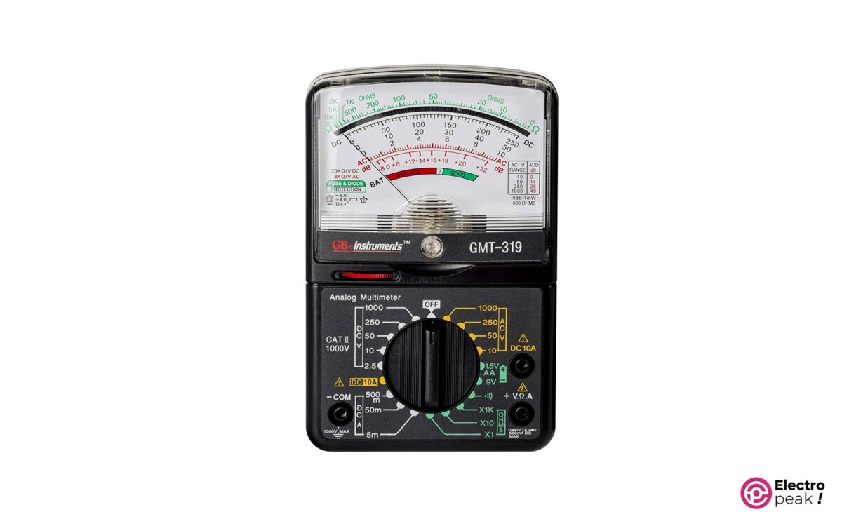
Dial Multimeter (analog)
Analog Multimeters display the measures using a graded scale and a moving pointer. The image below shows a model of an analog multimeter.
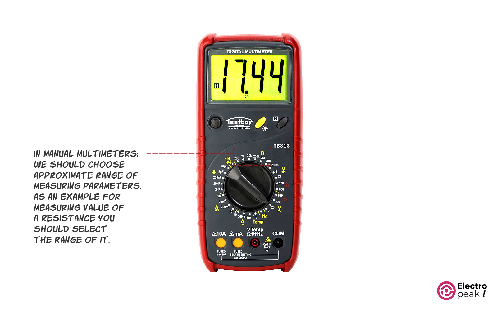
Digital Multimeter
Digital multimeters have an LCD screen that displays values as digital numbers, making them easier to work with. The image below shows a digital multimeter.

Multimeters fall into other categories based on their measurement range: (1) Auto-range, and (2) Manual.
Manual Multimeter
In these multimeters, you must first select the approximate range for the parameter you want to measure. For example, say you want to measure resistance. As you can see in the image below (blue box), several default ranges are on the multimeter. All you need to do is choose one of the ranges using the knob.
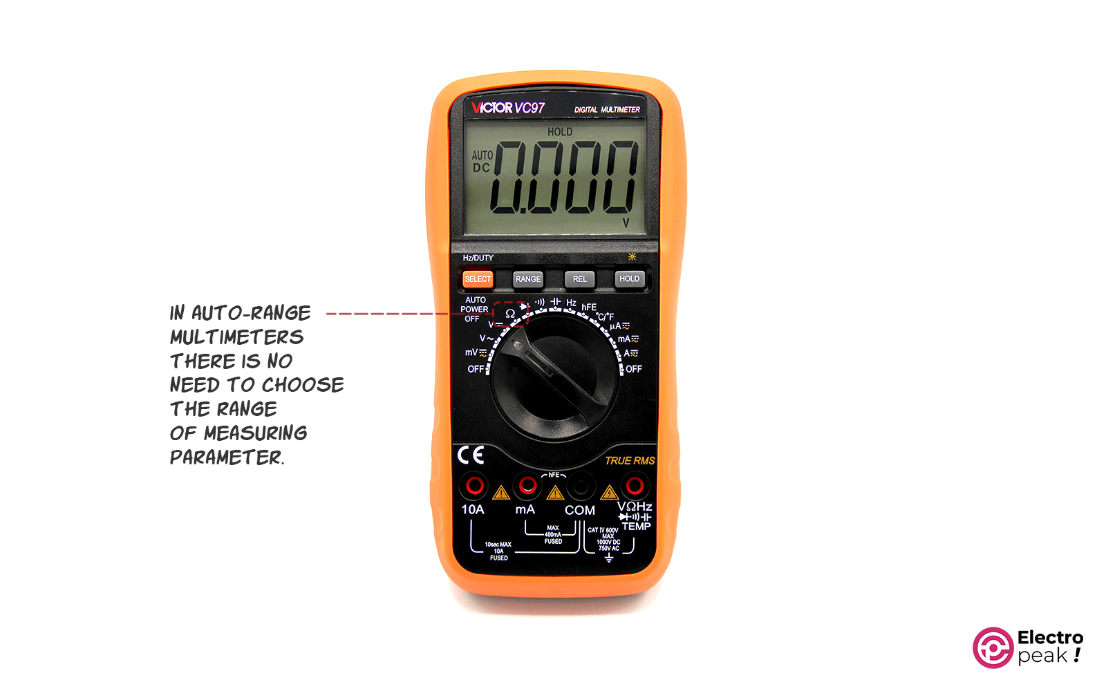
Auto-range Multimeter
Auto-range multimeters simplify the measurement process by automatically selecting the appropriate range, eliminating the need for manual selection.
For example, to measure resistance, set the selection knob to the “Ω” mode, and the multimeter will handle the range automatically (image below).
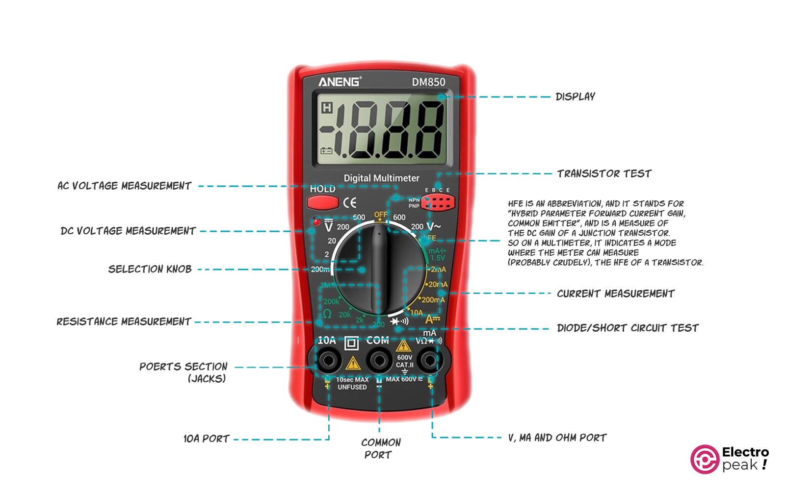
Different Parts of Multimeter
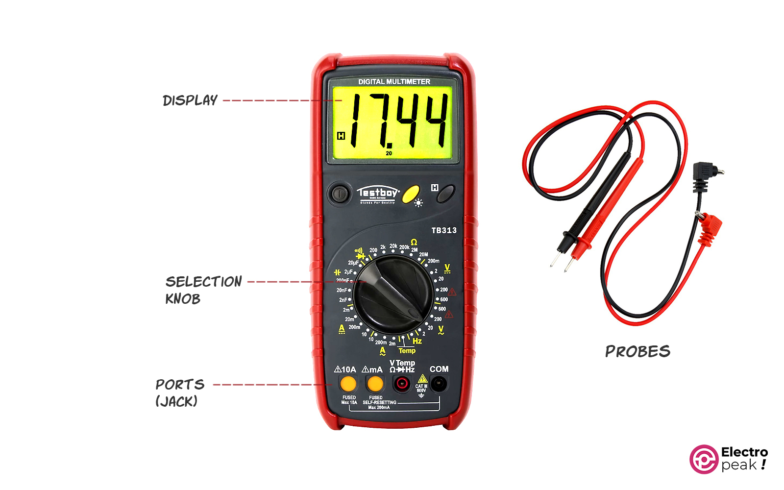
Display
A screen that shows the values.
Selection Knob
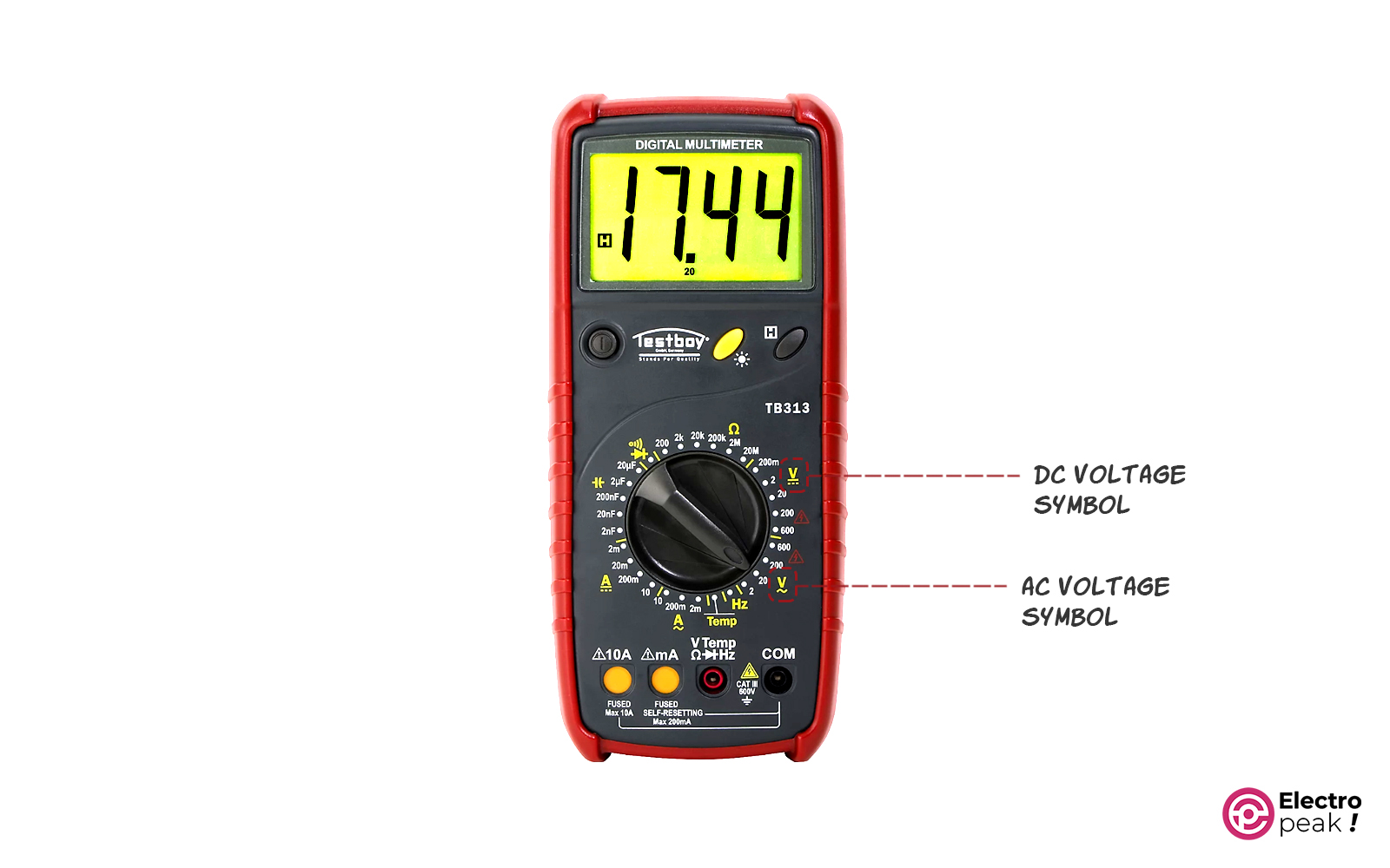
The “Selection Knob” allows you to specify what you want to measure. For example, to measure DC voltage, turn this knob to the “V” mode with straight lines.
Port
Ports are where we plug in the measurement probes.
Most multimeters have three ports:
- COM: the common port for the black probe.
- mAVΩ: the port for the red probe.
- 10A port: when we want to measure a current value higher than 200mA. In this case, we plug the red probe into this port and the black probe into the “COM” port.
When measuring high current values, it is often recommended to use a clamp meter.
In some multimeters, the “mAVΩ” port is divided into two separate ports: “VΩ” for voltage and resistance, and “µAmA” for current measurements in µA and mA. These multimeters usually offer higher resolutions for current values.
Measurement Probes
Red and black wires are used for the physical testing of electronic components. Each of these wires has a sharp tip on one end and a banana plug on the other. The tip should be connected to the component, while the banana plug is inserted into one of the ports on the multimeter.
Although there is no practical difference between the black and red probes, it is common practice to plug the black probe into the COM port and use it as Gnd when measuring voltage or current.
How to Use a Multimeter: Measuring Voltage
You can measure both AC and DC voltages using a multimeter.
On the other hand, the city power voltage is typically an AC voltage (Alternating Current).
- V with a straight line indicates DC voltage.
- V with a curved line indicates AC voltage.
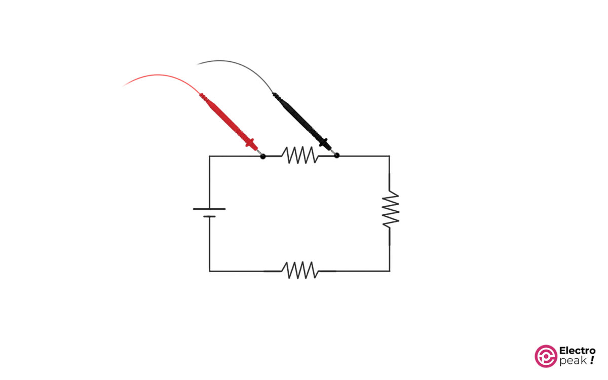
To measure the voltage drop across a component, connect the probes in parallel to the component terminals. For example, connect the probes to the resistor terminals as shown in the image below to measure the voltage drop.
To measure voltage, follow these steps:
- Step 1: Set the knob to voltage (V) mode (AC or DC). Specify the range if not using an auto-range multimeter.
- Step 2: Plug the black probe into the COM port and the red probe into the mAVΩ port.
- Step 3: Connect the red probe to the component’s positive terminal (where current enters) and the black probe to the negative terminal.
- Step 4:Read the value displayed on the screen.
This value is the voltage drop across the component. If the value is negative, it means that the red probe is connected to the negative terminal and the black probe to the positive terminal.
Please note that when measuring AC voltages, the values shown on the screen are in RMS (Root Mean Square), which is not covered in this article.
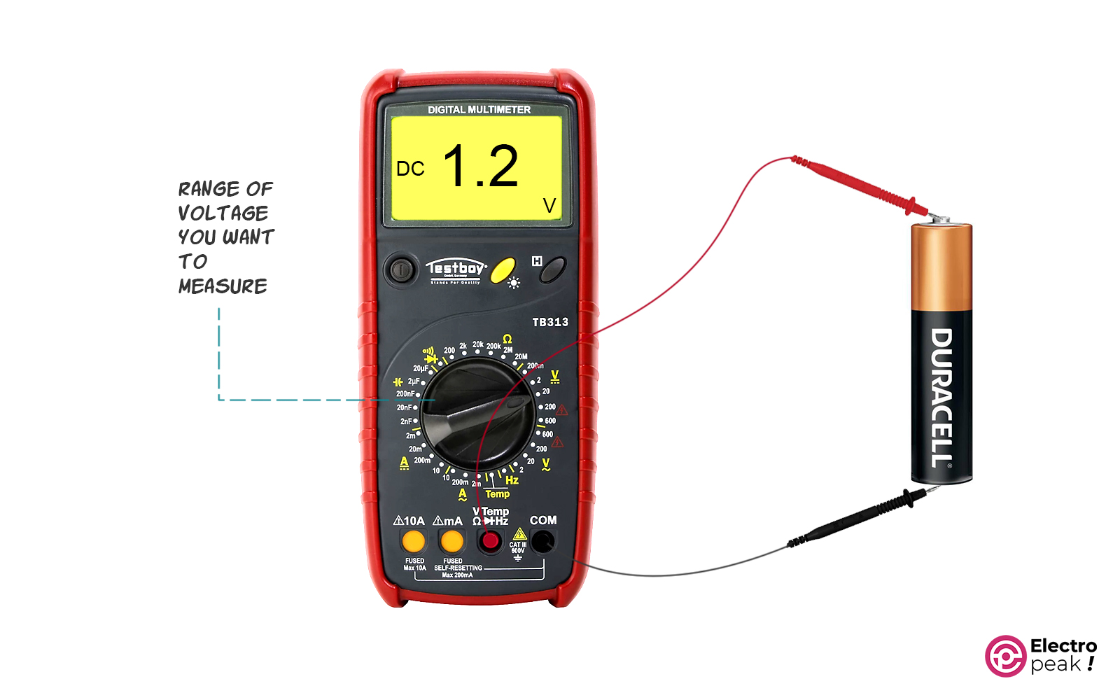
Battery Voltage Measurement
In this example, we will be measuring the voltage of a 1.5V battery. When selecting the range on the multimeter, it’s important to choose a setting that can accurately measure the 1.5V, such as the 2V range in this case. For those using an autorange multimeter, there is no need to manually select the range.
If the voltage value is unknown, it may be necessary to try several ranges when measuring the voltage of an unknown source. If the selected range is lower than the actual value, the display will show “1,” indicating that the voltage exceeds the selected range. Opting for a higher range will often allow the voltage value to be displayed, albeit with slightly less precision.
What happens if you switch the red and the black probe in Voltage measurement?
Nothing dangerous will happen. The multimeter displays a negative reading, which is not a cause for concern. When measuring voltage, the multimeter compares the voltage at the positive terminal to the common probe. For instance, the voltage at the positive terminal of the battery in relation to the common probe is 1.5V. If the probes are switched, defining the positive terminal as the common or zero point, the voltage at the negative terminal in relation to our new zero is -1.5V.
How to Use a Multimeter: Measuring Current
To measure current, connect the two tips in series with the open points, as shown in the image below
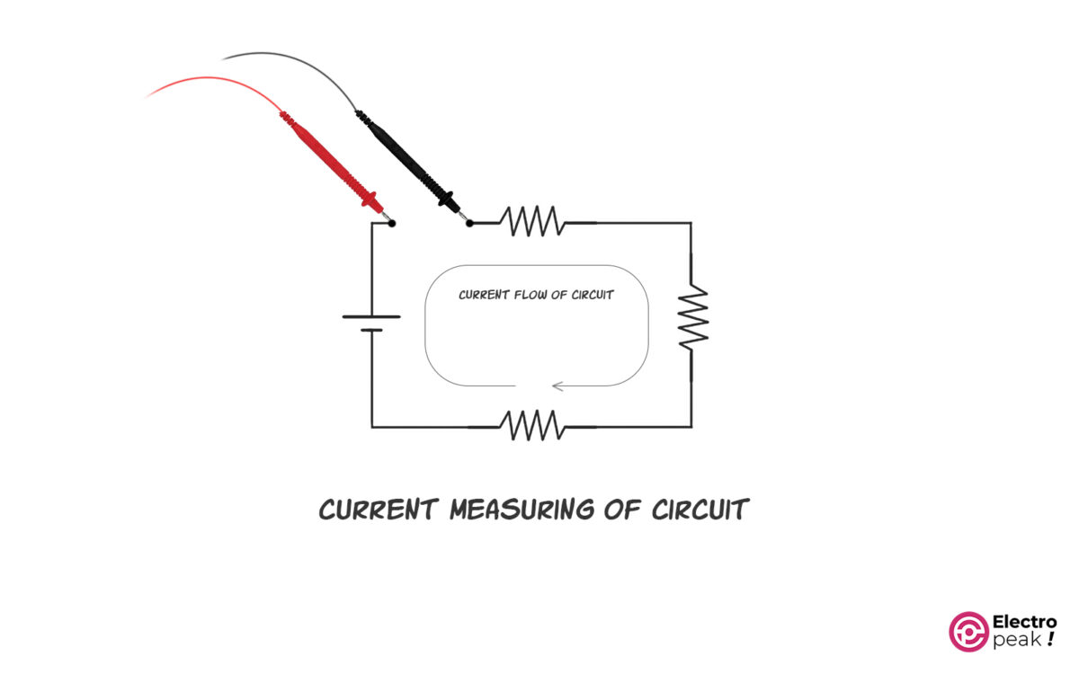
In the image above, the current passing through all the elements is the same. To help you understand, let’s use an example. Think of the current as water flowing through a pipe. The water flow will be the same everywhere unless a new inlet or outlet line is added to the main pipe.
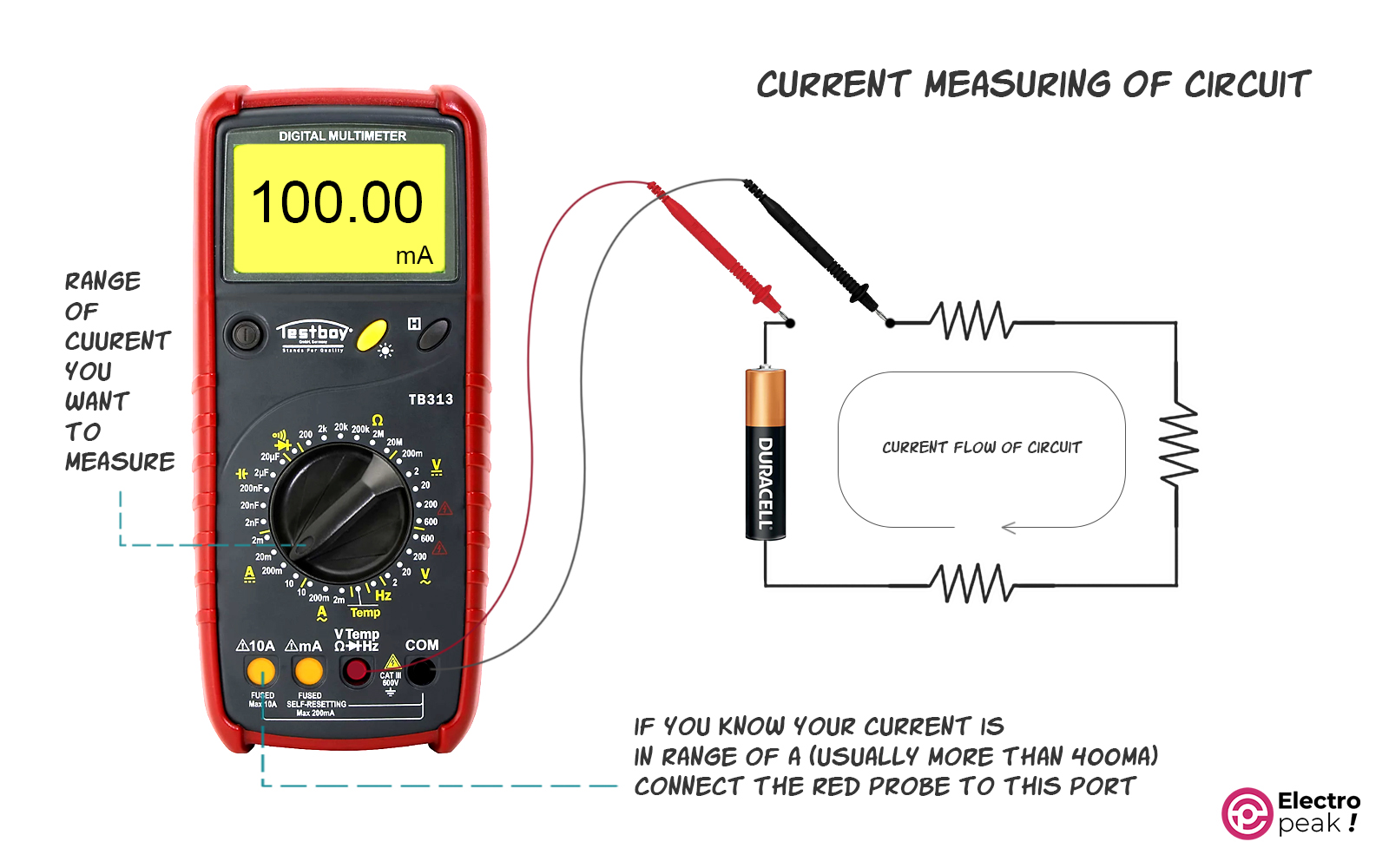
To measure the current using a multimeter, follow the steps below:
- Step 1: Set the knob to the current mode marked as “A.” Specify the range if not using an auto-range multimeter.
- Step 2: Plug the black probe into the COM port. Plug the red probe into the mAVΩ port if the current value is a few milliamps or less. However, if you are sure or even have doubts that the current is larger than 200-300 mA, plug the red probe into the “10A” port.
In addition, the multimeter can only handle an instant current of up to 10A. So, if a current of about 10A runs through it for more than a few seconds, the multimeter will be significantly damaged.
We use a clamp meter to measure large amounts of current such as household appliances or industrial power lines.
When measuring the current of a component—a resistor, for example—select one resistor terminal, break it, and then connect the two tips to the open points. In this scenario, the multimeter acts like a wire; when you disconnect it, the current value will be zero.
How to Use A Multimeter: Measuring Resistance
Understanding how to use a multimeter for measuring resistance is crucial for diagnosing electrical issues in various devices and circuits.
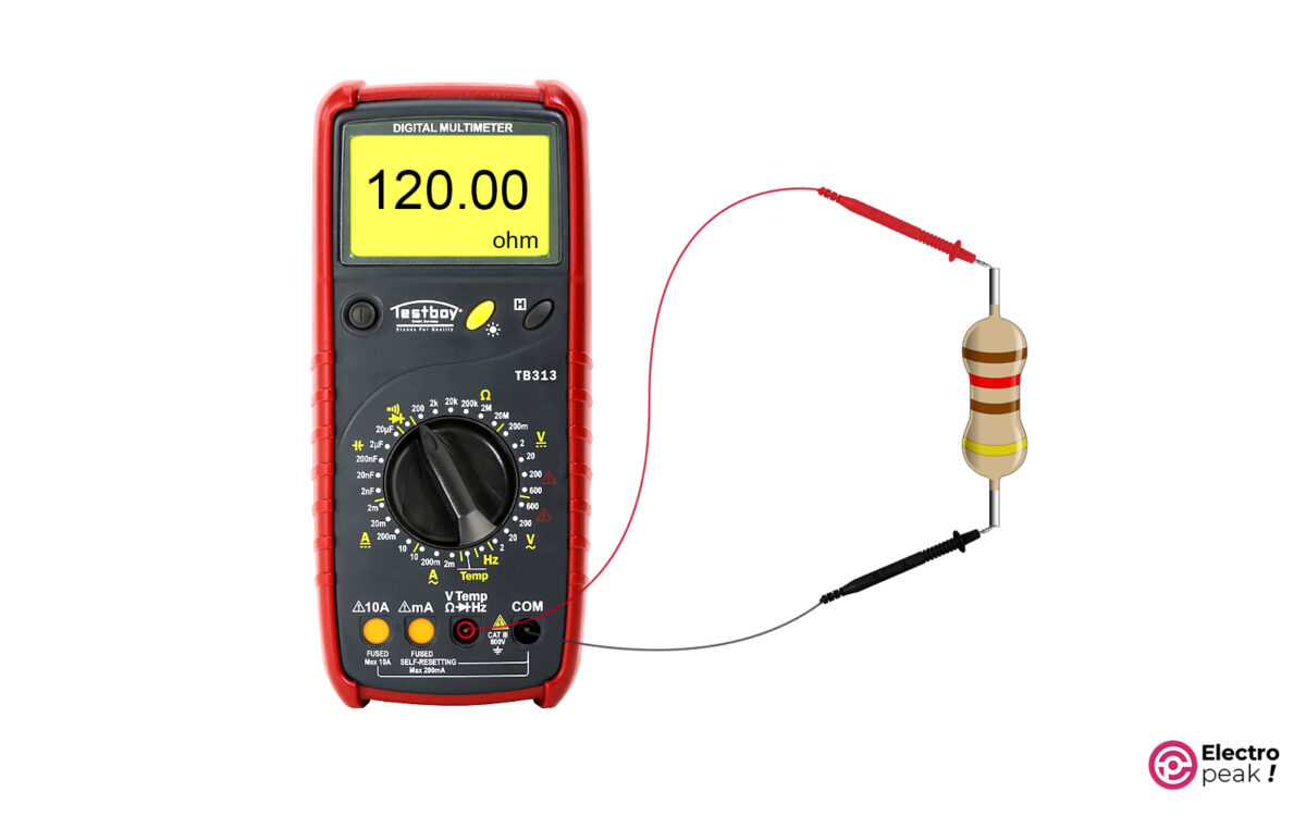
To measure resistance, follow these steps:
- Step 1: Set the knob to the resistance mode (“Ω” symbol). Specify the range if not using an auto-range multimeter.
- Step 2: As usual, plug the black probe into the COM port and the red probe into the mAVΩ port.
- Step 3: Connect the two probes in parallel with the two resistor terminals (image below). (Since resistors don’t have a positive or negative pin, it doesn’t matter which terminal you connect the probes to.)
How to Use A Multimeter: Continuity Test
The continuity test, a crucial technique in circuit repair and troubleshooting, is employed to ascertain the presence of a conductive path between two points. It is instrumental in identifying broken connections or unintended continuity within a circuit. To perform a continuity test, follow these steps on how to use a multimeter:
- Turn off the power supply or disconnect it from the circuit to ensure there is no voltage or current.
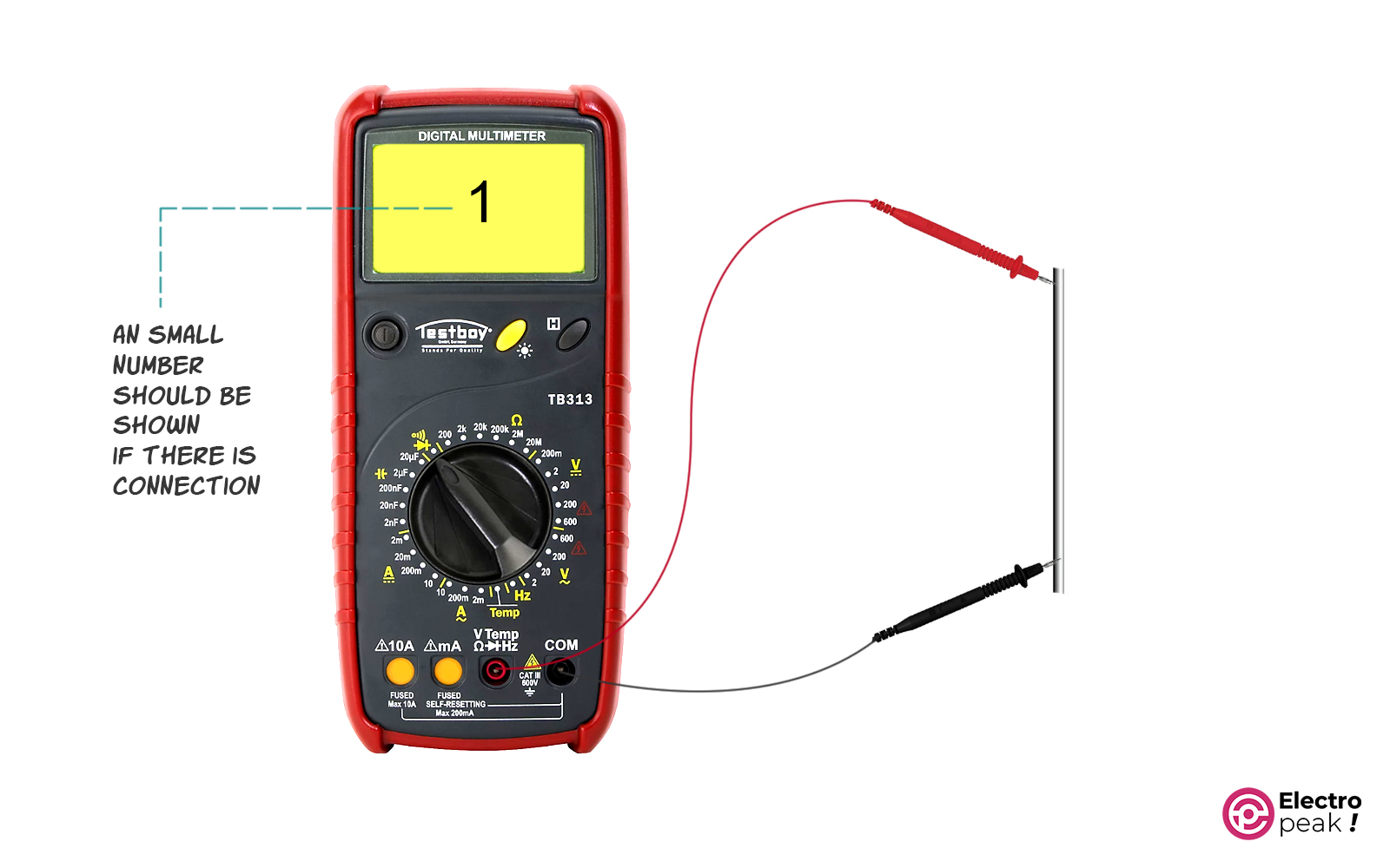
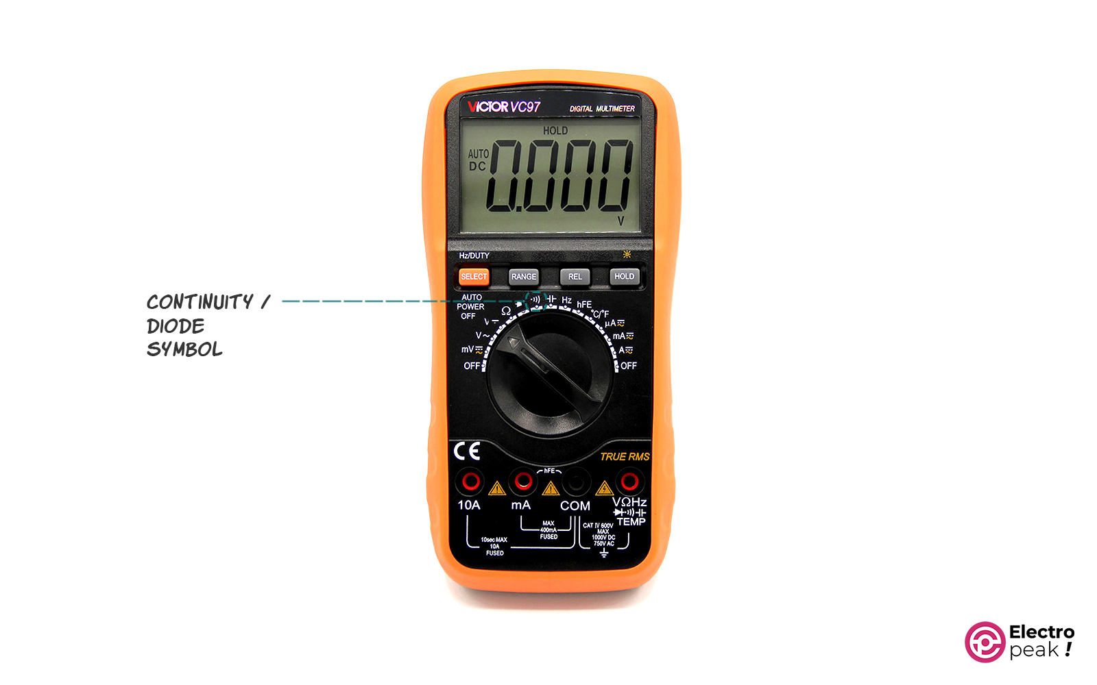
- Set the knob to the continuity test mode (a symbol like “♬” or similar to the image below.)

- As usual, plug the black probe into the COM port and the red probe into the mAVΩ port.
- To test the multimeter, press the tips against each other. You should hear a beep and see a small number (less than twenty or thirty) on the screen. This beep indicates continuity.
- Connect the tips to the points you want to test. If you hear a beep, it indicates continuity between the two points. And the number on the screen represents the resistance between them.
How to Use A Multimeter: Diode Test
Diode is one of the most popular components in electronic circuits. The diode test process is also quite simple.
First, set the knob to the diode test mode. (The diode test symbol looks the same as the diode electronic symbol shown in the image below. Also, the diode test and continuity test modes are often the same.
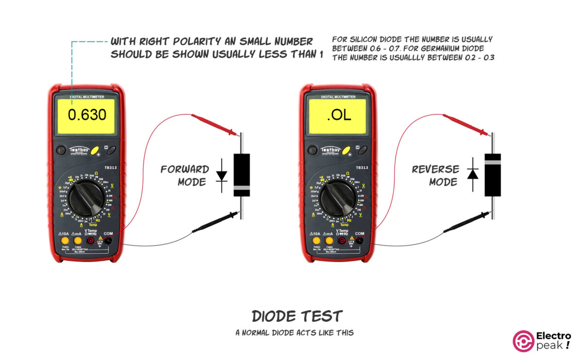
Press the red probe tip against the diode’s positive terminal and the black probe tip against the negative terminal. The display should show a number called the diode offset voltage, typically between 0.5 and 0.7 (refer to the diode’s datasheet for exact specifications if available).
Now, if the multimeter beeps or shows a very small value, it indicates that the diode is shorted and defective.
Switch the probes, connecting the positive terminal of the diode to the black probe and the negative terminal to the red probe. You should either see a very large number or the “OL” symbol on the screen. A beep also indicates that the diode is shorted and defective.
If you don’t know the polarity of the diode pins, the testing process remains the same: (1) connect the probes to the two diode pins and do the test, and (2) switch the pins and repeat the test. Respectively, a small number and a large number (or the “OL.” symbol) should be displayed on the screen.
In any case, the diode is broken if:
- you hear a beep.
- you see a large number or the “OL.” symbol on the screen.
- you see a small number on the screen.
When testing, f the diode is intact and you see a small number on the screen, the terminal connected to the red probe is the diode’s positive terminal.
How to Use A Multimeter: Diode-Bridge Test
What is a Diode Bridge?
A Diode bridge is a practical circuit commonly found in almost all power supplies and LED drivers. Its purpose is to rectify voltage.
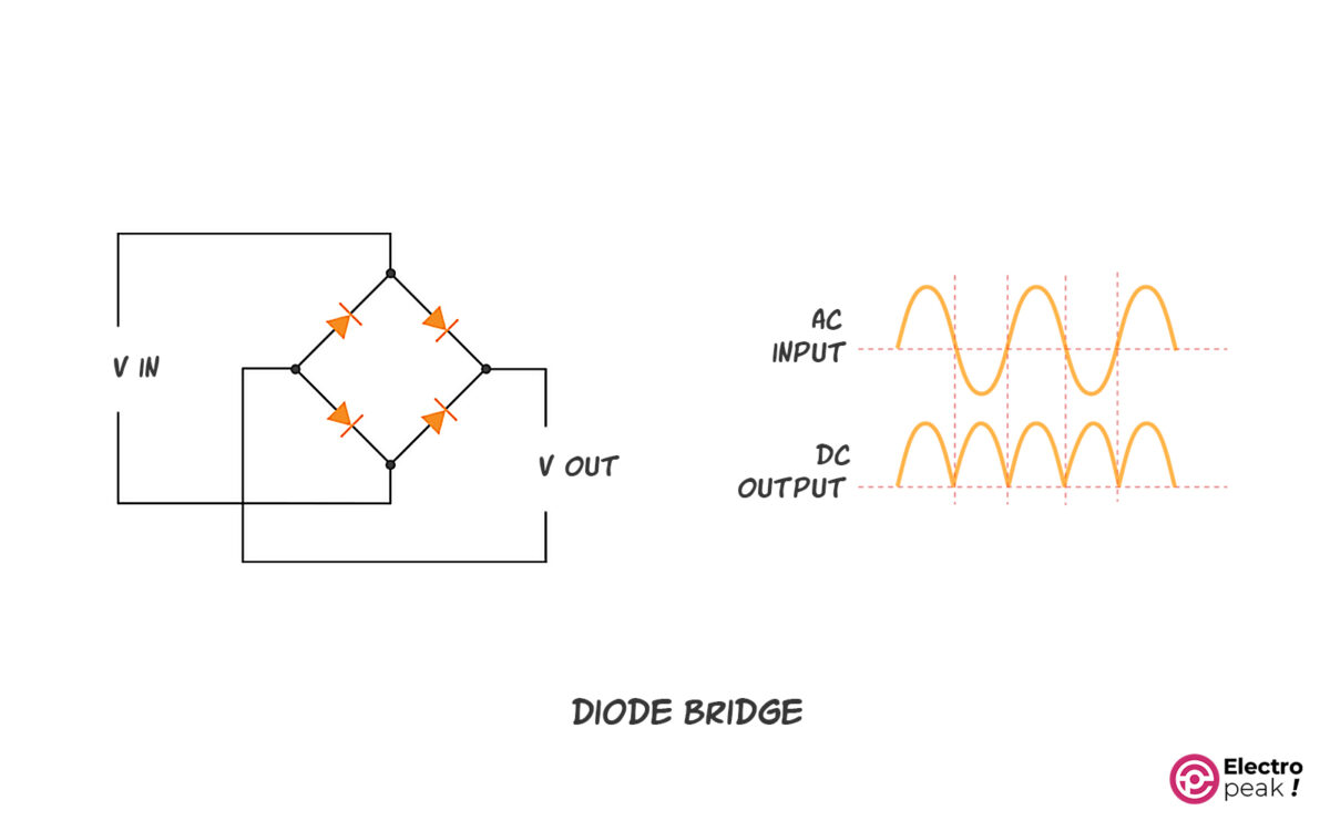
A diode bridge consists of four diodes: two input and two output pins. When a sinusoidal voltage is applied to the input pins, the output will show a completely positive voltage (the absolute value of the sinusoidal signal). In the image below, you can see the schematic of a diode bridge with its input and output pins (on the left).
The diode bridge is typically placed at the beginning of the circuit. If the diode bridge is installed on the board, it is easy to find the input and output pins.
In a diode bride, the current enters the circuit through the input pins, which have no polarity. The current then flows to the rest of the circuit through the output pins.
The diode bridge has positive and negative output pins. If you can’t differentiate the polarities or there is no mark on the board or diode bridge, follow these steps:
- Put the multimeter in diode test mode.
- Now you have to test four diodes.
- Connect the red probe to one of the input pins (image below). And then connect the black probe to one of the output pins. Next, connect the black probe to the other output pin. You should see the “OL.” symbol and a small number, respectively.
If you see a small number on the screen, the pin connected to the black probe is the positive pin of the diode bridge output.
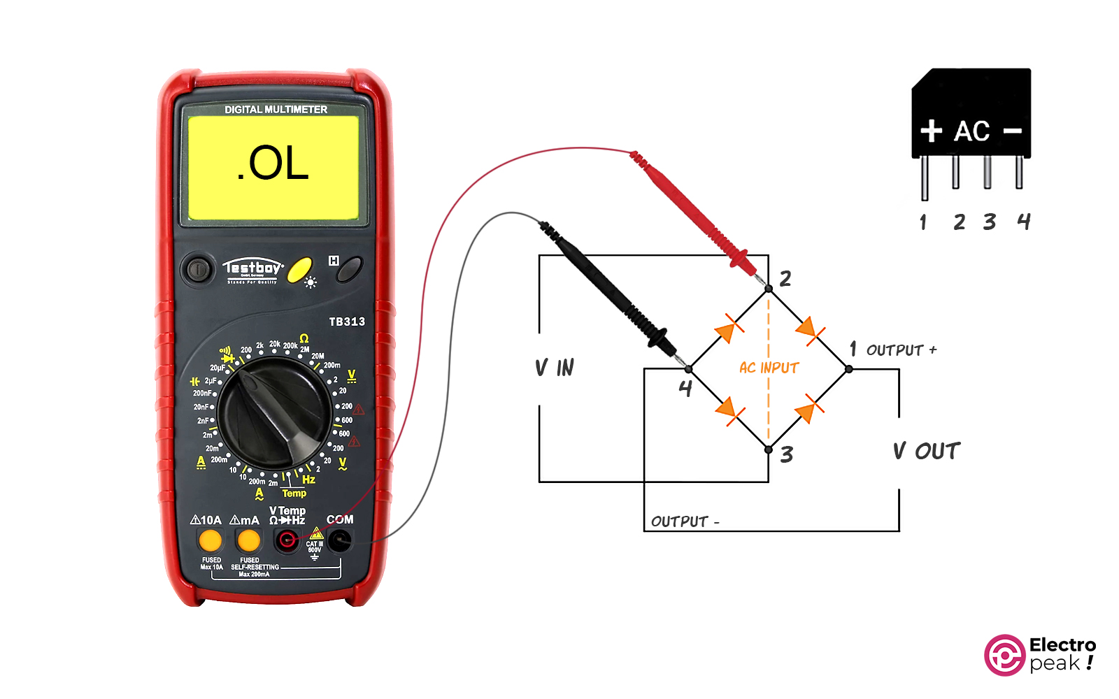
As mentioned, you need to test all four diodes to perform a complete test of the diode bridge. These tests are illustrated in the image below.
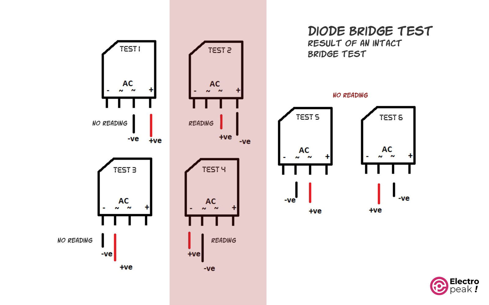
In the image above, the multimeter should display a small number for the yellow section and “OL.” for the rest.
Multimeter Symbols
So far, we have covered the main functions of a multimeter, yet they can do much more. Also, each of these functions has a symbol. For more details, you can see the image below.
Also, if you have any other questions related to electronics, you can share them with us in the ElectroPeak forum.
