
Product added to cart

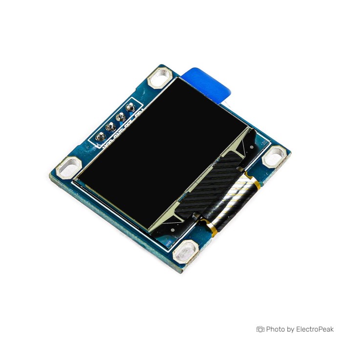
0.96inch 128x64 I2C OLED Display Module - Yellow and Blue
$2.5200
In stock
SKU
LCD-01-100
Volume discounts:
- +25 4 % $2.4200
- +100 6 % $2.3700
- +300 8 % $2.3200
- +500 10 % $2.2700
- +1000 12 % $2.2200
Ships in 2-3 business days, then:
Free delivery in 12-15 days by Tracked Economic Shipping on orders over $100.
Free delivery in 7-10 days by Express Shipping on orders over $300.
More shipping info

Shop with confidence Learn More
 0.66inch 64x48 I2C OLED Display Module - One Color Previous
0.96 Inch OLED Yellow Blue Display Review
This 0.96 inch yellow-and-blue 128×64 I2C OLED module provides a compact visual readout for microcontroller status screens, simple configuration menus, and live sensor monitors. Its self-emitting pixels deliver high contrast without a dedicated backlight, while the standard SSD1306 controller supports straightforward integration through established display libraries on several embedded platforms. With only two communication lines alongside power, it is a practical choice when microcontroller pins are limited.
This generic module is not intended for direct-sunlight visibility, full RGB graphics, or mission-critical commercial deployments that require strict batch-level traceability. For basic desktop readouts or prototype enclosures, it remains one of the simplest visual interfaces among small display modules to bring up.
Specifications of 0.96 Inch 128x64 I2C OLED Display Module - Yellow And Blue
- Display size: 0.96 inch
- Resolution: 64×128 pixels
- Resolution: 128x64
- Supply voltage: 3.3 volts
- Interface: I2C
- Driver chip: SSD1306
- PCB dimensions: 28.8x27 millimeters
- Display length: 26.6 millimeters
- Display width: 19.2 millimeters
- Color: Blue and Yellow
- Interface: IIC / I2C
- GND: Power Gound
- VCC: 2.2V-5.5V
- SCL: CLK clock (High level 2.2V-5.5V)
- SDA: MOSI data (High level 2.2V-5.5V)
- Power: 0.06W
- Wide power supply range: DC 3V-5V
- Temperature: -30 ° C to 70 ° C
- Dimension: 29.28 x 27.1 mm (LW)
- Compatible with 3.3V and 5V control chip I / O level
- OLED internal drive chip: SSD136
0.96 Inch OLED Specifications and Practical Limits
The 128×64 resolution provides enough pixel density for multiple rows of small monospace text, compact status icons, or simple line graphs. Because each OLED pixel emits its own light, dark areas draw virtually no power and black levels stay deep, avoiding the light bleed associated with standard edge-lit LCD screens. The published power figure is 0.06W, although actual draw varies with the number of illuminated pixels.
The yellow-and-blue output is divided into physical zones on the glass rather than provided by a full RGB matrix. The top band illuminates yellow, while the remaining lower area illuminates blue, with an unlit gap between them. This layout suits fixed title bars, system banners, or unit indicators above live sensor readouts, but it cannot display arbitrary colors across the screen. For the same 0.96 inch SSD1306 family in selectable single-color options, the MC096GW 0.96" I2C OLED Module is available in solid White, solid Blue, Yellow, or Blue and Yellow.
The published physical specifications include minor internal discrepancies worth noting before designing 3D-printed brackets or custom enclosures. PCB dimensions are listed as both 28.8×27 mm and 29.28×27.1 mm, while the visible display glass measures 26.6×19.2 mm. Operating voltage is likewise documented as 3.3 volts, 2.2V–5.5V, and DC 3V–5V. All original values remain in the specification block above. Verify your specific board before finalizing a rigid enclosure design.
0.96 Inch OLED I2C Wiring and Compatibility
This 0.96 inch OLED uses four connections: GND, VCC, SCL (clock), and SDA (data). The listing labels the SDA pin as "MOSI data," an internal SPI-oriented naming typo; in practice, it serves as the standard bidirectional I2C data line. Because the module is compatible with 3.3V and 5V control-chip I/O levels, it works cleanly with modern 3.3V boards and traditional 5V hardware.
At the controller level, the SSD1306 driver architecture is supported across Arduino, ESP32, ESP8266, Raspberry Pi, and STM32 platforms. Mainstream libraries including Adafruit SSD1306, paired with Adafruit GFX, and U8g2 provide mature rendering functions, custom fonts, and buffer handling. For step-by-step wiring instructions, see our Arduino SSD1306 OLED wiring guide. For interface comparisons, consult the SPI and I2C OLED interface guide.
The documentation does not specify a fixed I2C address for this board. Although 0x3C is standard for SSD1306 modules of this class, with 0x3D appearing on select hardware variants, an I2C scanner sketch during initial bench testing is the most dependable way to confirm the active address before configuring display firmware.
For a prototype connection to a host board, use four I2C jumper-wire connections with an I2C-capable Arduino test board. Building on a compact IoT footprint instead? The 0.66" I2C OLED Shield (WeMos D1 Mini) provides a direct-stacking form factor for ESP8266 boards and runs strictly at 3.3V with a 64×48 resolution.
0.96 Inch OLED Limitations and Setup Risks
This generic module is versatile for prototyping, but several practical constraints affect whether it suits your design. It is an unbranded component with no explicit revision tracking, CE/RoHS certification records, or published Mean Time Between Failures (MTBF) data. Community testing indicates occasional quality and component variation between production runs, including isolated reports of early module failure. The listing also does not state whether male pin headers are included or pre-soldered, so spare headers and basic soldering gear are wise to have ready.
A blank screen generally comes down to three factors:
- I2C address mismatches: Configuring software for 0x3D when the module is at 0x3C, or vice versa, halts initialization.
- Swapped signal lines: Reversing the SCL and SDA connections prevents the host from establishing bus communication.
- Incorrect library initialization: Using a 128×32 configuration instead of 128×64 distorts graphics or prevents correct output.
Two displays on one I2C bus must each respond to a distinct address. Because this module does not document an onboard address-selection solder jumper, multiple identical displays on the same bus lines are not assured out of the box. Outdoor use is also limited: OLED panels wash out in bright ambient sunlight, so they are better suited to indoor instruments or shaded housings.
Test the initial hookup on a breadboard test setup before permanent soldering to verify the address and avoid mistakes. For true RGB capability rather than fixed two-color bands, the 0.96" Full-Color TFT-IPS LCD (ST7735) uses an 80×160 backlit TFT panel with an 8-pin flat ribbon SPI interface.
0.96 Inch I2C OLED vs SPI OLED
The choice between I2C and SPI versions depends on available microcontroller pins and update-rate requirements. This I2C module needs four physical lines: ground, power, clock (SCL), and data (SDA). Its low pin count makes it easy to add to development boards already carrying multiple sensors, though shared I2C bus speed adds overhead when updating full-screen animations.
For rapid visual refreshes or responsive user interfaces, the 0.96" SPI OLED (Yellow & Blue) uses an SPI interface that transmits data at higher clock rates. It also needs additional dedicated controller pins, typically CS, DC, RESET, and SPI bus lines. If you do not need a 64-pixel vertical display height and want an ultra-narrow footprint for compact handhelds or wearable prototypes, the 0.91" 128x32 I2C OLED offers a 38×12 mm monochrome white alternative.
For wiring and timing considerations across both communication protocols, refer to the SPI and I2C OLED interface guide.
0.96 Inch OLED Accessories and First Power-On Check
Before mounting the display permanently in an enclosure, prepare the following hardware to verify operation:
Required
- Microcontroller: An I2C-capable Arduino test board, ESP32, or similar embedded controller.
- Wiring: Flexible four I2C jumper-wire connections for power and signal routing.
- Pin header: 0.1-inch header strip; soldering may be required if pins are not pre-installed.
Recommended
- Prototyping surface: A breadboard test setup to secure components during bench testing.
- Diagnostic sketch: A standard microcontroller I2C scanner routine to identify the hardware address.
- Multimeter: To verify voltage rail stability on custom power supplies.
Optional
- Enclosure or protective bezel: Sized for the display's 26.6×19.2 mm active area.
- Logic level shifter: For strict 3.3V-only controllers if input levels require hardware matching.
First Power-On Sequence
- If the board arrived unpopulated, solder a 4-pin male header to the GND, VCC, SCL, and SDA through-holes.
- Connect GND to the microcontroller ground rail, VCC to 3.3V or 5V, SCL to your board's I2C clock pin, and SDA to the I2C data pin.
- Install an SSD1306-compatible library, such as Adafruit SSD1306 through the Arduino Library Manager. The listing's "SSD136" entry is a typo for SSD1306.
- Open a default 128×64 I2C example sketch and verify the address in the sketch, defaulting to 0x3C.
- Compile and upload the code. The screen should illuminate with test graphics or text, showing yellow in the upper sector and blue across the rest.
- If the display remains completely dark, upload an I2C scanner sketch to confirm whether the device acknowledges communication on the bus.
For a fuller software walkthrough, see our Arduino SSD1306 OLED wiring guide.
0.96 Inch SSD1306 OLED FAQ
Is this a 128×64 OLED or a 128×32 OLED?
This module provides a 128×64 display format. The specification block includes a reversed "64×128 pixels" entry, and some external listings occasionally confuse this form factor with 128×32, but the physical panel uses a 128-column by 64-row layout.
What controller library does this 0.96 inch SSD1306 OLED use?
It uses standard SSD1306 display drivers. Common Arduino ecosystem choices include Adafruit SSD1306, used alongside Adafruit GFX, and the U8g2 library; both support full 128×64 I2C initialization.
What I2C address does this SSD1306 OLED use?
The factory address is not explicitly stated in the module documentation. SSD1306 I2C displays commonly use 0x3C, though 0x3D is possible on certain hardware variations; an I2C scanner sketch is the fastest way to confirm your unit's address.
Can this OLED connect to a 3.3V or 5V microcontroller?
Yes, the module is designed for broad compatibility, though the published power specifications simultaneously list 3.3 volts, 2.2V–5.5V, and DC 3V–5V. It operates with both 3.3V and 5V control logic levels.
Can I use two of these OLED displays on the same I2C bus?
Only if each display responds to a different address. Two identical devices with the same default address cannot share an I2C bus, and this module has no documented solder pads for address modification.
Why would an SSD1306 OLED screen stay blank?
A blank display is commonly caused by swapped SCL and SDA lines, an I2C address that does not match your sketch initialization, a loose connection on un-soldered header pins, or a 128×32 driver configuration selected instead of 128×64.
Is this a full-color display?
No. This is a fixed two-color yellow-and-blue display. The upper pixel rows illuminate yellow and the lower rows illuminate blue. If your build requires full RGB graphics, the 0.96" Full-Color TFT-IPS LCD (ST7735) provides an alternative 80×160 color panel using an SPI interface.
Should I choose this I2C OLED or the SPI version?
Choose this I2C display when you need a clean setup with minimal wiring, using only two signal lines. Select the 0.96" SPI OLED (Yellow & Blue) when your firmware runs rapid animations or frequent screen redraws that need the higher throughput of an SPI bus.
For segment units, character screens, and other panel types, browse our broader collection of other display formats.
Purchase Decision Summary
- Ideal for: Compact Arduino, ESP32, ESP8266, and Raspberry Pi builds that need a high-contrast 128×64 display for status messages, sensor readings, or configuration menus using minimal wiring.
- Maybe for: Small handheld or battery-powered enclosures where physical dimensions fit, provided you verify the board's supply requirements and I2C address during bench testing.
- Consider another option if: You require true RGB color, daylight-readable screens for direct sun, confirmed address modification for multi-display setups, or formal industrial certifications with traceable production batch controls.
Buying Checklist
- ✓ Confirm your user interface fits a 128×64 pixel area.
- ✓ Confirm a fixed yellow-top, blue-bottom color layout suits your screen design.
- ✓ Ensure your host board has two free I2C pins (SCL and SDA).
- ✓ Note the published voltage entries (3.3V, 2.2V–5.5V, DC 3V–5V) before connecting custom power rails.
- ✓ Verify that your development framework supports standard SSD1306 libraries.
- ✓ Have access to an I2C scanner sketch for initial address verification.
- ✓ Have spare male header pins and soldering equipment on hand in case headers are uninstalled.
- ✓ Use four I2C jumper-wire connections for direct breadboard hookups.
- ✓ Select the MC096GW 0.96" I2C OLED Module if you prefer selectable monochrome color options.
- ✓ Select the 0.66" I2C OLED Shield (WeMos D1 Mini) for dedicated ESP8266 shield mounting.
- ✓ Select the 0.96" SPI OLED (Yellow & Blue) if your firmware demands faster SPI data transfers.
| Display Size | 0.96 inch |
|---|---|
| Display Size Range | 0.99 inch and smaller |
| Display Resolution | 128x64 pixels |
| Display Driver | SSD1306 |
| Display Interface | I2C |
| Panle Type | PM OLED |
| Display Color Type | Yellow and Blue |
| Touchscreen Type | None |
| Backlight Type | None |
| Viewing Angle (°) | >160° |
| Operating Temp (°C) | -30 ° C to 70 ° C |
| Operating Voltage (V) | 3.3V - 5V |
| Pins | 4 |
| Operating Current (mA) | 0.06WnOverall Dimensions: 29.28 x 27.1 mm (LW) |
Write Your Own Review

Please complete your information below to login.
Sign In
Create New Account