Contents

Fingerprint Attendance System w/ Real-time Online Data Backup

Overview

Nowadays, learning about IoT devices operation and implementation is so essential due to the increasing use of IoT systems. In this tutorial, we are going to make a fingerprint attendance device with Arduino, which in addition to storing the logging information and working hours on the memory card, uploads this information on the Thingspeak platform as soon as it is connected to the Internet and You can download this information from the panel in various formats, such as CSV.

What You Will Learn

What is Thingspeak?

Iot (Internet of things) is a platform in which there are a number of things connected to the Internet, interacting with individuals and other devices, and usually, upload data on cloud computing for analysis.

Thingspeak is an IoT platform that lets you display and collect live data in cloud computing.

Interfacing with Thingspeak and Uploading Data

Follow the steps below to start the Thingspeak connection:

Step 1) Enter the Thingspeak.com website and create an account.

Step 2) Login after activating your account and click on New Channel in the My Channel section.

Step 3) In the new window opened for you, write a name for your panel and any description if it is necessary. Determine the number of fields that you need by assigning their names. The remaining parts are optional. Save the panel after completing the information.

Step 4) Now go to API Keys in your panel.
Step 5) You need the Channel ID and Write API Key to transmit data, so write them down.

Step 6) Download the Thingspeak library and add it to your Arduino IDE.

The Thingspeak library

Step 7) Go to the Arduino IDE. Open the WriteMultipleFiels from examples part and enter the SSID, Password, Channel ID, and Write API Key values.

secrets.h file

/*
  WriteMultipleFields
  
  Description: Writes values to fields 1,2,3,4 and status in a single Thingspeak update every 20 seconds.
  
  Hardware: ESP8266 based boards
  
  !!! IMPORTANT - Modify the secrets.h file for this project with your network connection and Thingspeak channel details. !!!
  
  Note:
  - Requires ESP8266WiFi library and ESP8622 board add-on. See https://github.com/esp8266/Arduino for details.
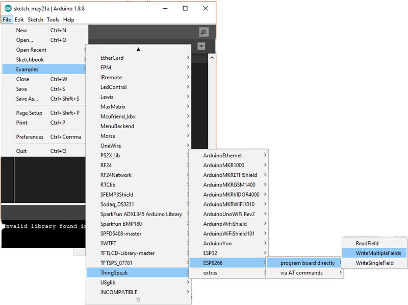
  - Select the target hardware from the Tools->Board menu
  - This example is written for a network using WPA encryption. For WEP or WPA, change the WiFi.begin() call accordingly.
  
  Thingspeak ( https://www.Thingspeak.com ) is an analytic IoT platform service that allows you to aggregate, visualize, and 
  analyze live data streams in the cloud. Visit https://www.Thingspeak.com to sign up for a free account and create a channel.  
  
  Documentation for the Thingspeak Communication Library for Arduino is in the README.md folder where the library was installed.
  See https://www.mathworks.com/help/Thingspeak/index.html for the full Thingspeak documentation.
  
  For licensing information, see the accompanying license file.
  
  Copyright 2018, The MathWorks, Inc.
*/

#include "ThingSpeak.h"
#include "secrets.h"
#include <ESP8266WiFi.h>

char ssid[] = SECRET_SSID;   // your network SSID (name) 
char pass[] = SECRET_PASS;   // your network password
int keyIndex = 0;            // your network key Index number (needed only for WEP)
WiFiClient  client;

unsigned long myChannelNumber = SECRET_CH_ID;
const char * myWriteAPIKey = SECRET_WRITE_APIKEY;

// Initialize our values
int number1 = 0;
int number2 = random(0,100);
int number3 = random(0,100);
int number4 = random(0,100);
String myStatus = "";

void setup() {
  Serial.begin(115200);  // Initialize serial

  WiFi.mode(WIFI_STA); 
  ThingSpeak.begin(client);  // Initialize Thingspeak
}

void loop() {

  // Connect or reconnect to WiFi
  if(WiFi.status() != WL_CONNECTED){
    Serial.print("Attempting to connect to SSID: ");
    Serial.println(SECRET_SSID);
    while(WiFi.status() != WL_CONNECTED){
      WiFi.begin(ssid, pass);  // Connect to WPA/WPA2 network. Change this line if using open or WEP network
      Serial.print(".");
      delay(5000);     
    } 
    Serial.println("\nConnected.");
  }

  // set the fields with the values
  ThingSpeak.setField(1, number1);
  ThingSpeak.setField(2, number2);
  ThingSpeak.setField(3, number3);
  ThingSpeak.setField(4, number4);

  // figure out the status message
  if(number1 > number2){
    myStatus = String("field1 is greater than field2"); 
  }
  else if(number1 < number2){
    myStatus = String("field1 is less than field2");
  }
  else{
    myStatus = String("field1 equals field2");
  }
  
  // set the status
  ThingSpeak.setStatus(myStatus);
  
  // write to the Thingspeak channel
  int x = ThingSpeak.writeFields(myChannelNumber, myWriteAPIKey);
  if(x == 200){
    Serial.println("Channel update successful.");
  }
  else{
    Serial.println("Problem updating channel. HTTP error code " + String(x));
  }
  
  // change the values
  number1++;
  if(number1 > 99){
    number1 = 0;
  }
  number2 = random(0,100);
  number3 = random(0,100);
  number4 = random(0,100);
  
  delay(20000); // Wait 20 seconds to update the channel again
}

After uploading the code, you will see some random numbers uploaded in fields 1 to 4 of your panel. The same structured code is used in the attendance system for uploading data.

Note
Wait at least 15 seconds between each time you upload the data on the Thingspeak panel.

Creating Attendance System Using the Fingerprint Sensor and Arduino

In this system, after registering the entry and exit of a person by his fingerprint, the information including date, name, time of arrival, time of departure and working hours for the employee are stored on the SD card. Then this information will be sent to Thingspeak at the time you have specified. In the absence of the Internet connection, unpublished data is stored and will be forwarded to Thingspeak as soon as it is connected to the Internet. Since the information is stored in the EEPROM of the microcontroller, they will not be lost in case of a power outage.

Required Materials

Hardware Components

Arduino Mega 2560 R3 × 1
R301T Fingerprint sensor × 1
Micro SD TF Card Adapter Module × 1
DS3231 I2C RTC Module × 1
3.5" TFT Color Display Screen Module × 1
NodeMCU ESP8266 ESP-12E Board × 1
5V Active Buzzer × 1
Male to Female Jumper Wire × 1

Software Apps

Arduino IDE

Circuit

After connecting all modules, put the LCD shield on the Arduino.
Tip
Since the LCD Shield covers some of the Arduino pins, you can border wire to a specific pin from the bottom of the board, if you need these pin.

Code

You need the following libraries for this code:

Adafruit-Fingerprint-Sensor-Library

Adafruit-GFX-Library

MCUFRIEND_kbv

RTClib

Now download the following code and upload it to your Arduino. This code is written for 11 people with default names, but you can change them and remove it from the default mode. To register a new name, simply connect the device to your computer and press the key to enter the register mode, then open the Serial Monitor and follow the registration process as is shown on the Serial Monitor.

Download the code from here:

You can learn more about using an SD card, the clock module, and the LCD in the following links:

SD Card Module w/ Arduino: How to Read/Write Data

How to Use DS1307 RTC Module with Arduino & Make a Reminder

Absolute Beginner’s Guide to TFT LCD Displays by Arduino.

Nodemcu executes the task of uploading the information in this system. It takes the uploading information from Arduino through the serial port and returns the status of uploading to Arduino. Upload the following code on your Nodemcu.

#include "ThingSpeak.h"
#include <ESP8266WiFi.h>


char ssid[] = "YOUR SSID";
char pass[] = "SSID PASSWORD";
WiFiClient  client;

unsigned long myChannelNumber = YOUR CHANNEL ID;
const char * myWriteAPIKey = "YOUR CHANNEL WRITE API KEY";

String Final = "";

String Date = "";
String Enter = "";
String Exit = "";
String Name = "";
String WT = "";

void String_Analyze(String input) {
  int index1, index2, index3, index4;
  index1 =  input.indexOf('*', 0);
  index2 =  input.indexOf('*', index1 + 1);
  index3 =  input.indexOf('*', index2 + 1);
  index4 =  input.lastIndexOf('*');

  Name = input;
  Date = input;
  Enter = input;
  Exit = input;
  WT = input;

  Name.remove(index1);

  Date.remove(index2);
  Date.remove(0, index1 + 1);

  Enter.remove(index3);
  Enter.remove(0, index2 + 1);

  Exit.remove(index4);
  Exit.remove(0, index3 + 1);

  WT.remove(0, index4 + 1);
}

void Get_String()
{
  while (Serial.available()) {

    Final = Serial.readString(); // read the incoming data as string
    //Serial.println(Final);
  }
}
void setup() {

  Serial.begin(9600);
  WiFi.mode(WIFI_STA);
  ThingSpeak.begin(client);
  pinMode(LED_BUILTIN, OUTPUT);
  digitalWrite(LED_BUILTIN, HIGH);
}


void loop() {

  if (WiFi.status() != WL_CONNECTED) {
    //Serial.print("Attempting to connect to SSID: ");
    // Serial.println(ssid);
    while (WiFi.status() != WL_CONNECTED) {
      WiFi.begin(ssid, pass);  // Connect to WPA/WPA2 network. Change this line if using open or WEP network
      Serial.print("0");
      delay(5000);
    }
  }
  digitalWrite(LED_BUILTIN, LOW);
  //Serial.println("\nConnected.");

  Get_String();
  String_Analyze(Final);
  if (!Final.equals(""))
  {
    ThingSpeak.setField(1, Date);
    ThingSpeak.setField(2, Name);
    ThingSpeak.setField(3, Enter);
    ThingSpeak.setField(4, Exit);
    ThingSpeak.setField(5, WT);

    int x = ThingSpeak.writeFields(myChannelNumber, myWriteAPIKey);
    if (x == 200) {
      delay(100);
      Serial.print("1");
    }
    else {
      delay(100);
      Serial.print("0");
    }

    delay(17000);
    Final = "";
  }
}
First, change the Channel ID and Write API Key according to your Thingspeak Panel. The String_Analuze (); function in this code divides the Nodemcu input strings into the date, name, arrival and departure time, and working hours, and sends this information to Thingspeak. Then if the uploading process is successful, it sends the character “1”, and otherwise it sends the character “0” to the Arduino.

Assembling the Attendance Device

You can use the following maps and Plexiglass with different colors or any other material to build the body of the attendance device.

Download the device body laser cut map from here:

After placing electronic components and assembling the entire body, install it in the desired location. Now, just plug a 12V adapter to the device and it starts working.

What’s Next?

  • Try to use more icons on the LCD.
  • Try to add an RFID option to the system.
  • Try to upload the data on the google spreadsheets instead of Thingspeak.
Liked What You See?​
Get Updates And Learn From The Best​

Comments (7)

  • asis Reply

    compilation terminated. it’s show no file icons.h please help.
    ———————————
    /tmp/171554489/scan_finger/scan_finger.ino:13:10: fatal error: icons.h: No such file or directory

    #include “icons.h”

    ^~~~~~~~~

    compilation terminated.

    exit status 1

    February 6, 2020 at 4:56 pm
    • Saeed Hosseini Reply

      Add your desired icon code to a text file and name this to icone.h and put this to your project directory.

      March 1, 2020 at 6:20 am
  • Salman Reply

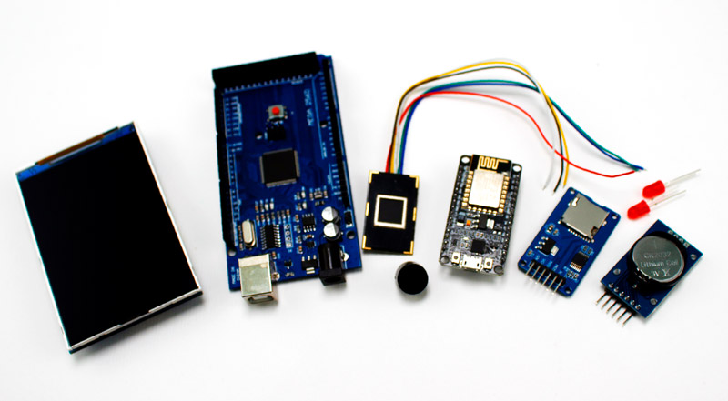
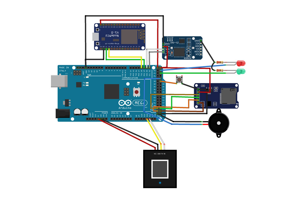
    Hi, i am Salman – I am going to try this attendance system. But, not understand the circuit, i don’t know what is that Right side to the NodeMCU, where is RT-Clock Module and u don’t give buzzer in component section. Please help me regarding circuit, Thank you

    May 24, 2021 at 8:05 am
    • Mehran Maleki Reply

      Hi. The module on the right side of the NodeMCU in the “Required Material” image is the MicroSD Card used to store data. And the module on the right side of the NodeMCU in the “Circuit” image is the RTC module. You can easily figure out which is which just by opening the purchase links of the modules and compare their real pictures with the circuit in this tutorial.
      The link to the buzzer is also added to the “Hardware Components” section.

      May 25, 2021 at 1:17 pm
  • Aqil Reply

    Hi, I would like to inquire regarding the circuit. I am very new to this. Is there a specific need for an Arduino board in this case? because I heard that NodeMCU ESP32 can function almost the same without an Arduino controller.

    September 30, 2021 at 4:19 am
    • Mehran Maleki Reply

      Hi,
      No, you don’t necessarily need to use an Arduino board. Actually, an ESP32 based development board can do the same or even offer more capabilities. So, you can replace the Arduino board in this circuit with an ESP32 board.

      October 2, 2021 at 8:52 am
  • Fluxx Reply

    void showmsgXY(int x, int y, int sz, const GFXfont *f, const char *msg)

    hello please i get an error message ” GFXfont dows not name a file:” please how can i fix this issue so as to move on with the compilation?

    May 23, 2022 at 1:53 am

Leave a Reply

Your email address will not be published. Required fields are marked *