
Product added to cart

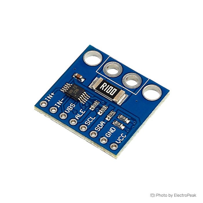
INA226 Voltage Current Power Monitoring Module
$1.2500
In stock
SKU
SEN-04-057
Volume discounts:
- +50 5 % $1.1900
- +100 7 % $1.1600
- +300 10 % $1.1300
- +500 11 % $1.1100
- +1000 14 % $1.0800
Ships in 2-3 business days, then:
Free delivery in 12-15 days by Tracked Economic Shipping on orders over $100.
Free delivery in 7-10 days by Express Shipping on orders over $300.
More shipping info

Shop with confidence Learn More
 ACS758LCB Current Sensor Module Previous
INA226 Voltage Current Power Monitoring Module Review
The INA226 Voltage Current Power Monitoring Module is a single-channel DC voltage, current, and power monitor that communicates over an I2C bus. Built around the INA226 monitor IC, it combines bus-voltage monitoring up to 36 V with bidirectional current sensing across an onboard shunt resistor. It suits developers monitoring a dedicated DC power rail who can inspect the physical board, configure shunt calibration in firmware, and verify measurements on the bench.
The fitted shunt resistance, continuous current rating, board pinout, and physical dimensions are not published for this specific board. It is not a plug-and-play meter for unknown loads. Developers who need guaranteed continuous-current ratings, galvanic isolation, AC current measurement, or turnkey factory-calibrated readouts should consider other approaches in our catalog of current and voltage monitoring modules.
Specifications of INA226 Voltage Current Power Monitoring Module
- Common Mode Voltage:36V (max)
- Input Offset:10uV (max)
- Input Offset Drift:0.02uV/C (typical)
- CMRR:126dB (min)
- Bandwidth:7KHz
- Supply Voltage:5.5V (max)
- Operating Temperature Range:-40~125 celsius
- Special Features:alert function; bi-directional;I 2C; low-side capable
- Bus Voltage Sensing Range:0 V to 36 V
- ADC Resolution:up to 16 bits
- Sensing Placement:High-Side or Low-Side Sensing
- Measurements Reported:Current, Voltage, and Power
- Gain Error:0.1% (max)
INA226 Voltage Current Power Monitoring Module Specifications and Calibration
The INA226 IC electrical ratings define its measurement capability, but applying them to a physical breakout board requires care. The 0 V to 36 V range refers to the common-mode bus voltage that the sense pins can tolerate relative to ground. It is separate from the logic supply input (VCC), which has a maximum rating of 5.5 V. Applying high bus voltages to the logic supply pins will damage the controller.
The INA226 measures the small voltage drop across an inline shunt resistor connected between its input pins, IN+ and IN−. Internally, the IC uses an analog-to-digital converter with up to 16 bits of resolution and a full-scale shunt measurement range of ±81.92 mV. An internal multiplier calculates power from the bus-voltage and shunt-current readings. The IC specifies an input offset of 10 µV maximum, a common-mode rejection ratio (CMRR) of 126 dB minimum, and a maximum gain error of 0.1%. These are IC-level silicon figures, not total system measurement accuracy.
| Specification | Published Value | Why It Matters in Practice |
|---|---|---|
| Bus Voltage Range | 0 V to 36 V | Defines the DC voltage that can be monitored. Suitable for 5 V, 12 V, and 24 V rails, but must not be connected to AC mains or higher-voltage DC supplies. |
| ADC Resolution | Up to 16 bits | Provides fine measurement granularity for small voltage and current changes, though overall reading accuracy remains limited by shunt tolerance and thermal drift. |
| Gain Error | 0.1% (max) | Reflects internal amplifier gain accuracy on the chip. Assembled system accuracy depends on the tolerance and temperature coefficient of the installed shunt. |
| Bandwidth | 7 kHz | Represents the internal analog bandwidth of the input stage. Practical sampling rates are determined by software-configured conversion times and averaging selections. |
| Supply Voltage | 5.5 V (max) | The logic supply limit of the chip (operating range 2.7 V to 5.5 V). The breakout board must be powered from a regulated logic rail, never from the monitored 12 V, 24 V, or 36 V bus. |
| Operating Temperature | -40 to 125 °C | Specifies the silicon temperature tolerance. Connectors, solder joints, and PCB traces on an assembled board are not rated for extreme industrial environments. |
Current and power cannot be read accurately out of the box until the firmware calibration registers are configured. The IC measures voltage across the shunt rather than current directly, so the host microcontroller must be given the exact shunt resistance value and a chosen current least-significant-bit (LSB) scaling factor. For example, if an INA226 module carries a 0.1 Ω shunt, the ±81.92 mV input limit gives a measurement ceiling of approximately ±0.819 A (0.08192 V / 0.1 Ω). With a 0.01 Ω shunt, the IC saturation limit becomes approximately ±8.19 A. These figures show the relationship between shunt resistance and measurement headroom; they do not state the thermal or continuous current limit of this specific board.
For custom bench setups that need a known high-power current path, developers sometimes use an external 10A current shunt resistor. This requires isolating the onboard shunt pads and routing external sense wires to the module inputs.
INA226 Voltage Current Power Monitoring Module I2C Wiring and Compatibility
The host controller communicates through a standard two-wire I2C interface using serial data (SDA) and serial clock (SCL) lines. This module operates strictly as an I2C slave peripheral, so no USB driver installation is required. Host platforms communicate through hardware I2C peripherals or software bit-banging routines.
The INA226 architecture is supported across major embedded ecosystems. Mature libraries and driver implementations are available for Arduino, ESP-IDF on the ESP32 platform, ESPHome for Home Assistant integrations, and the native ina2xx hardware monitoring driver in the Linux kernel for single-board computers such as the Raspberry Pi.
| System Area | Compatibility Level | Implementation Detail |
|---|---|---|
| Host Microcontrollers | Arduino, ESP32, Raspberry Pi, Linux | Requires standard I2C lines (SDA, SCL) and common ground reference. |
| Logic Levels | Board-specific (inspect before use) | The IC operates between 2.7 V and 5.5 V. Onboard pull-up resistor voltage and level-shifting provisions are not documented. |
| Sense Topologies | High-side or low-side sensing | The IC supports both placements. High-side sensing monitors current without disturbing the ground return of the load circuit. |
| I2C Bus Addressing | 0x40 to 0x4F (IC capability) | The IC supports 16 hardware addresses. The default address and available solder jumpers on this board must be confirmed by scanning. |
| ALERT Output | IC feature (board routing unverified) | The IC provides a programmable threshold alert output, but physical routing to an exterior pin header is not verified on this board. |
| AC / Mains Measurement | Incompatible | Lacks galvanic isolation, high-voltage clearance, and safety certifications. Strictly for DC low-voltage monitoring. |
Verify the silkscreen markings on the delivered PCB before wiring. The sense terminals, commonly designated IN+ and IN−, must be installed strictly in series with the load. In a high-side arrangement, IN+ connects to the DC power source and IN− connects to the positive supply side of the load. If the board has a separate VBUS terminal, connect it to the positive rail for bus-voltage measurement relative to circuit ground.
For bench prototyping, a breadboard jumper wire kit provides a straightforward way to establish logic lines between the breakout and host development board. To monitor telemetry across multiple independent power rails, use the INA3221 Triple Channel Sensor Module, which provides three separate DC monitoring channels on one board through a single I2C interface.
INA226 Voltage Current Power Monitoring Module Limitations
The main purchase limitation is the lack of published board-level specifications for the fitted shunt resistor, terminal blocks, and continuous current capability. The INA226 IC itself is fully documented by its manufacturer. The safe current-carrying capacity of an assembled module, however, depends on copper trace width, PCB thickness, connector ratings, and thermal dissipation from the surface-mount shunt resistor.
Several operational limitations require attention during system design:
- Unspecified shunt resistance: The resistance value, power rating, and tolerance of the onboard shunt are not published. A generic board carrying a 0.1 Ω resistor will clip readings above approximately 0.819 A and generate significant heat at 1 A or higher.
- Potential calibration mismatch: If firmware defaults to a 0.1 Ω shunt while the board carries a 0.01 Ω or 0.02 Ω resistor, voltage readings can appear plausible while current and power values are inaccurate by a factor of 5 to 10.
- Voltage limits vs. transient surges: The 36 V common-mode rating is an absolute limit for the IC sense pins. It provides no headroom for inductive voltage spikes, inductive kickback, or unregulated vehicle electrical systems that exceed 36 V.
- Lack of electrical isolation: The sense inputs share a ground reference through the board or host circuit. This module is unsafe for AC mains, grid-tied solar arrays, or circuits where the measured ground differs from the microcontroller ground.
- Unconfirmed board features: Solder bridge address options, ALERT pin routing, and logic pull-up voltages vary across board revisions and cannot be assumed before physical inspection.
Use a different sensor architecture when the application requires isolated current sensing or higher current ranges:
- Low-current AC or DC measurement with galvanic isolation calls for the ACS712 Current Sensor (±5A), which provides 2.1 kV RMS isolation through Hall-effect sensing.
- For heavy DC loads, the ACS758LCB Current Sensor (50A) has an integrated conductor capable of measuring up to 50 A with minimal insertion resistance.
- High-voltage industrial setups can use the WCS Series Hall Current Sensor, which provides 4000 V RMS isolation and adjustable overcurrent detection.
- Commercial or industrial DC monitoring may require the SUI-201 DC Energy Metering Module, a fully isolated platform with Modbus-RTU communications.
INA226 Current Sensor Module Alternatives for Single-Rail and Multi-Rail Monitoring
Choose a power monitor based on the DC bus operating voltage, total load current, number of rails to monitor, and whether isolation is required. Embedded developers have several options for different project requirements.
For single-rail DC systems below 26 V, the INA219 I2C Current Sensor Module is a standard alternative. The INA219 family provides 12-bit ADC conversion up to 26 V, making it suited to basic 5 V and 12 V hobby projects that do not need the higher resolution or 36 V input range of the INA226.
Monitoring several power supplies, or both battery input and output at once, can consume board space and bus addresses when using individual modules. The INA3221 Triple Channel Sensor Module places three independent shunt-sensing channels on one PCB and measures bus voltages from 0 V to 26 V per channel over one I2C interface.
Loads above 10 A or applications involving line voltages call for Hall-effect or isolated sensing modules rather than direct resistive shunts. The ACS712 Current Sensor (±5A), ACS758LCB Current Sensor (50A), and WCS Series Hall Current Sensor electrically isolate the high-current conductor from low-voltage microcontroller logic. This helps prevent ground loops and protects control hardware from voltage spikes.
For standalone testing of USB power supplies, cables, and battery banks without writing firmware, an embedded sensor is unnecessary. The FNIRSI-FNB38 USB Tester includes a color display, protocol triggering, and direct inline USB connectors. In commercial equipment racks, the SUI-201 DC Energy Metering Module provides complete electrical isolation and Modbus communication for industrial DC energy logging.
Compare physical dimensions, interface protocols, and current ranges across our broader collection of current and voltage monitoring modules.
INA226 Voltage Current Power Monitoring Module Quick Start
Before installing the module in a permanent circuit, use this test-bench verification sequence to confirm communication and calibrate the readings.
- Inspect the board: Examine the surface-mount shunt resistor, typically labeled R100 for 0.1 Ω or R010 for 0.01 Ω. Note whether screw terminals or header pins are supplied for load connections, and check the silkscreen labels for IN+, IN−, VBUS, VCC, and GND.
- Connect logic power: Wire GND to your microcontroller ground and connect VCC to a regulated 3.3 V or 5 V supply. Do not connect the monitored load voltage to VCC.
- Wire the I2C bus: Connect SDA and SCL to the matching hardware I2C pins on your microcontroller.
- Scan the I2C address: Run an I2C address scanner sketch on your host controller. The device should acknowledge at an address between 0x40 and 0x4F.
- Wire the test load in series: Connect a benchtop DC power supply, set below 36 V, to the positive rail. Route positive current through the IN+ terminal, out of the IN− terminal, through a known resistive load, and back to the power supply negative terminal. Connect circuit ground to the module ground.
- Configure firmware registers: In your software environment—Arduino library, ESPHome component, or Linux
ina2xxconfiguration—set the detected I2C address and enter the measured or marked shunt resistance value. - Verify measurement data: Compare the reported bus voltage with a trusted digital multimeter. Measure load current with the multimeter in series, then confirm that reported current and power agree with the physical meter readings.
For general I2C shunt-wiring principles, register configuration, and microcontroller communication, see our related guide on interfacing INA219 current sensor module with Arduino.
Common initial setup errors include:
- Connecting the high-voltage monitored bus directly to the VCC logic supply pin.
- Assuming an I2C address of 0x40 without performing a bus scan.
- Wiring the sense terminals in parallel across the power supply rather than in series with the load, creating a dead short.
- Leaving default 0.1 Ω library calibration in place when the board is fitted with a different shunt resistor.
- Using thin breadboard jumper wires to carry high load currents, causing false voltage drops and overheating.
INA226 Voltage Current Power Monitoring Module Accessories
Operating the INA226 module requires supporting components and test accessories based on your deployment stage.
Required Accessories
- I2C Host Microcontroller: An Arduino, ESP32, Raspberry Pi, or compatible development board with an I2C master peripheral and common ground.
- Regulated Logic Power Supply: A clean 2.7 V to 5.5 V DC source to power the internal logic and analog circuitry of the INA226 IC.
- Appropriate Load Wiring: Wire gauge and terminal connections matched to the continuous current of your measured DC load.
- Firmware Configuration: Drivers or library software configured with the correct shunt resistance value and current-LSB calibration parameters.
Recommended Accessories
- Breadboard Prototyping Platform: An 830 points breadboard provides a stable surface for bench testing logic connections and low-current circuits.
- Logic Wiring: A breadboard jumper wire kit connects I2C communication and logic power lines.
- Reference Multimeter and Known Load: A verified digital multimeter and power resistor validate voltage, current polarity, and calibration accuracy.
- Circuit Protection: An inline fuse and transient voltage suppressor on the measured DC bus protect against short circuits and overvoltage transients.
Optional Accessories
- External Shunt: A high-power 10A current shunt resistor for developers engineering a separate sensing path that bypasses onboard PCB thermal limits.
- ALERT Interrupt Line: A pull-up resistor and dedicated GPIO line to use the hardware alert interrupt if the ALERT pin is exposed on the board.
- Visual Display: An external I2C LCD or OLED display for local readout without an attached computer.
INA226 Voltage Current Power Monitoring Module FAQ
Can I power the INA226 Voltage Current Power Monitoring Module from 12 V, 24 V, or 36 V?
No. The board's logic power supply, VCC, must not be connected to 12 V, 24 V, or 36 V. The INA226 IC has a maximum operating supply rating of 5.5 V and is designed to run from a regulated 3.3 V or 5 V logic rail. The 0 V to 36 V rating applies only to the common-mode bus voltage monitored at the sense terminals, not to the logic supply.
How many amps can the INA226 current sensor module measure?
The maximum measurable current depends entirely on the installed shunt resistor value and the board's thermal limits. The INA226 IC has an internal full-scale shunt measurement limit of ±81.92 mV. With a 0.1 Ω shunt, the IC clips at approximately ±0.819 A. With a 0.01 Ω shunt, it reaches ±8.19 A before saturation. The specific shunt value on this board is not published and must be inspected on arrival.
Does the INA226 module work with Arduino, ESP32, Raspberry Pi, and ESPHome?
Yes. The INA226 is broadly supported across Arduino, ESP32 through Arduino or ESP-IDF, ESPHome, and Linux systems using the native ina2xx kernel driver. Because communication uses standard I2C, any host with an I2C master port can collect measurements after the correct address and shunt calibration values are defined in software.
Why does INA226 voltage look correct but current or power look wrong?
Current and power readings are incorrect when the firmware calibration register does not match the physical resistance of the onboard shunt. The IC measures bus voltage directly, while it calculates current mathematically from the shunt voltage drop. If firmware assumes a 0.1 Ω resistor but a 0.01 Ω resistor is fitted, reported current will be off by a factor of ten. Check the shunt marking, verify current direction, and calibrate with a known load.
What is the default INA226 I2C address?
The default address for this specific breakout is not published. The INA226 IC supports 16 hardware addresses between 0x40 and 0x4F. Run an I2C scanner routine on your host microcontroller to determine the physical address before deploying code.
Can I connect several INA226 modules to one I2C bus?
Yes, multiple modules can share the same I2C clock and data lines when each unit has a unique address. The INA226 IC supports up to 16 distinct addresses through pin strapping, though the number of accessible address options on this board depends on which solder pads are exposed. For multi-channel monitoring on one board, consider the INA3221 Triple Channel Sensor Module.
Is the ALERT pin available on this board?
Routing of the ALERT pin to an exterior header or solder pad is unverified on this breakout. The INA226 silicon includes over-voltage, under-voltage, and power-limit threshold notification features, but physical access to this pin must be verified on the delivered PCB.
Is INA226 better than INA219?
The INA226 provides higher ADC resolution, up to 16 bits versus 12 bits, and a higher bus-voltage rating, 36 V versus 26 V, than the INA219 family. The INA219 I2C Current Sensor Module remains widely used for basic DC circuits under 26 V where standard resolution is sufficient.
Can this module measure AC current or mains power?
No. This module cannot measure AC current or mains power and is designed solely for low-voltage DC power monitoring. It does not provide the galvanic isolation, creepage distance, or high-voltage safety ratings required for mains electrical circuits.
INA226 Voltage Current Power Monitoring Module Purchase Decision Summary
Ideal for:
- Developers monitoring a single DC power rail operating between 0 V and 36 V with an I2C microcontroller.
- Projects that require bidirectional current measurement and automated onboard power calculation.
- Bench environments where developers can inspect the installed shunt, calibrate firmware, and verify readings against a reference meter.
Maybe for:
- Battery charge and discharge logging on 12 V or 24 V systems where load currents remain well within the thermal capacity of small surface-mount shunts.
- ESPHome or Raspberry Pi telemetry setups where custom shunt values can be declared easily in software.
Consider another option if:
- You require factory-calibrated, plug-and-play current readings without manual verification.
- Your circuit involves AC mains, high voltages, or needs galvanic isolation between the measured rail and logic controller.
- You need multi-rail monitoring on a single compact board or documented continuous current ratings above several amperes.
INA226 Voltage Current Power Monitoring Module Buying Checklist
- Confirm your monitored DC bus voltage remains at or below 36 V under all conditions.
- Verify that you have a separate, regulated 2.7 V to 5.5 V power source for the logic supply (VCC).
- Plan to inspect the physical board markings upon arrival to determine the installed shunt resistance value.
- Ensure your load current will not exceed the physical dissipation and trace limits of the board.
- Confirm your microcontroller provides standard I2C communication (SDA, SCL) and shared ground.
- Have a digital multimeter and known test load available to perform initial calibration.
- Select an isolated Hall-effect sensor if your project involves AC power, mains voltages, or potential ground loops.
| Interface Type | I2C |
|---|---|
| Operating Voltage (V) | 2.7V to 5.5V |
| Operating Current (mA) | 0.33mA (Typical) |
| Operating Temp (°C) | -40 to 125 celsius |
| Output Type | I2C |
| Accuracy | 0.1% Gain Error (max) |
| Resolution | 16 bits |
| Bandwidth | 7KHz |
| Voltage Range (V) | 0 to 36V |
| Material | PCB |
| Model | INA226 |
| Channels | 1-channel |
| Display Type | None |
| Parameters | Current, Voltage, Power |
| Protocols | I2C |
Write Your Own Review

Please complete your information below to login.
Sign In
Create New Account