Contents

Interfacing INA219 Current Sensor Module with Arduino

If you’re looking to interface the INA219 current sensor module with an Arduino, you’ve come to the right place. In this guide, we’ll walk you through the necessary steps to get your setup up and running smoothly.

INA219 Current Sensor Module Features

The INA219 module is used to measure both current and voltage at the same time. This module uses I2C communication to transfer the voltage and current data.

Other features:

  • Measurement accuracy: 1%
  • Maximum measured voltage: 26V
  • Maximum measured current: 3.2A.
Note

Pay attention to inductive loads switching. Its instantaneous voltages may damage the circuit.

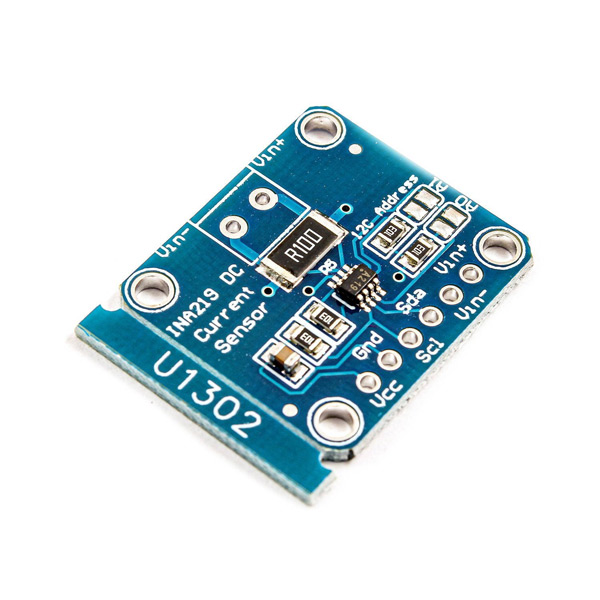
Download the Datasheet of this sensor here.

INA219 Current Sensor Module Pinout

This Module has 6 pins:

  • VCC: Module power supply
  • GND: Ground
  • SDA: I2C Data
  • SCL: I2C Clock
  • Vin-: Load terminal pin
  • Vin+: Source terminal pin

You can see the pinout of this module in the image below.

Required Material

Hardware component

Arduino UNO R3 × 1
INA219 DC CURRENT SENSOR × 1
Male to Male jumper wire × 1
SYB-170 Mini Small Bread Board × 1

Software Apps

Arduino IDE
Note

Apart from the components above, you also need an LED and a 220ohm resistor for this tutorial.

Step-by-Step Guide to Interfacing INA219 Current Sensor Module with Arduino

Step 1: Circuit

The following circuit shows how you should connect Arduino to INA219 sensor. Connect wires accordingly.

Note

The orange wire (3.3 volts) is called the Bus voltage and the blue wire is called the Load voltage.

Shunt voltage is the potential difference between the Load voltage and the Bus voltage.

Step 2: Library

Go to Library manager, search for INA219 and install the Adafruit INA219 library.

Note

If you need more help with installing a library on Arduino, read this tutorial: How to Install an Arduino Library

Step 3: Code

Upload the following code to Arduino.

 /*
  DC-Current-Voltage-Sensor-Module
  made on 06 Feb 2021
  
Home
based on Adafruit Example */ #include <Wire.h> #include <Adafruit_INA219.h> Adafruit_INA219 ina219; void setup(void) { Serial.begin(115200); while (!Serial) { // will pause Zero, Leonardo, etc until serial console opens delay(1); } uint32_t currentFrequency; Serial.println("Hello!"); if (! ina219.begin()) { Serial.println("Failed to find INA219 chip"); while (1) { delay(10); } } Serial.println("Measuring voltage and current with INA219 ..."); } void loop(void) { float shuntvoltage = 0; float busvoltage = 0; float current_mA = 0; float loadvoltage = 0; float power_mW = 0; shuntvoltage = ina219.getShuntVoltage_mV(); busvoltage = ina219.getBusVoltage_V(); current_mA = ina219.getCurrent_mA(); power_mW = ina219.getPower_mW(); loadvoltage = busvoltage + (shuntvoltage / 1000); Serial.print("Bus Voltage: "); Serial.print(busvoltage); Serial.println(" V"); Serial.print("Shunt Voltage: "); Serial.print(shuntvoltage); Serial.println(" mV"); Serial.print("Load Voltage: "); Serial.print(loadvoltage); Serial.println(" V"); Serial.print("Current: "); Serial.print(current_mA); Serial.println(" mA"); Serial.print("Power: "); Serial.print(power_mW); Serial.println(" mW"); Serial.println(""); delay(2000); }

This code is for measuring both voltage and current. We want to find the source voltage and the voltage and current of the load. The source voltage is 3.3V and the load voltage is actually the LED voltage. The current passing through LED is also calculated using the shunt voltage. The shunt resistance creates a very small potential difference called the shunt voltage.

These parameters will be displayed on the Serial Monitor: Bus, Shunt and Load voltage, current and power:

By following these simple steps, you’ll successfully interface the INA219 current sensor module with your Arduino board. Enjoy the accuracy and versatility that the INA219 module brings to your projects!

Remember, if you encounter any issues or require additional support, feel free to reach out. Happy tinkering with the INA219!

Liked What You See?​
Get Updates And Learn From The Best​

Comments (14)

  • Rob Davidowitz Reply

    I have followed your instruction to the letter and get the following error message
    Failed to find INA219 chip”

    June 20, 2022 at 2:49 pm
    • Mehran Maleki Reply

      Hi.
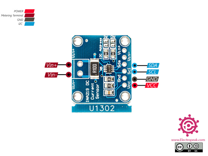
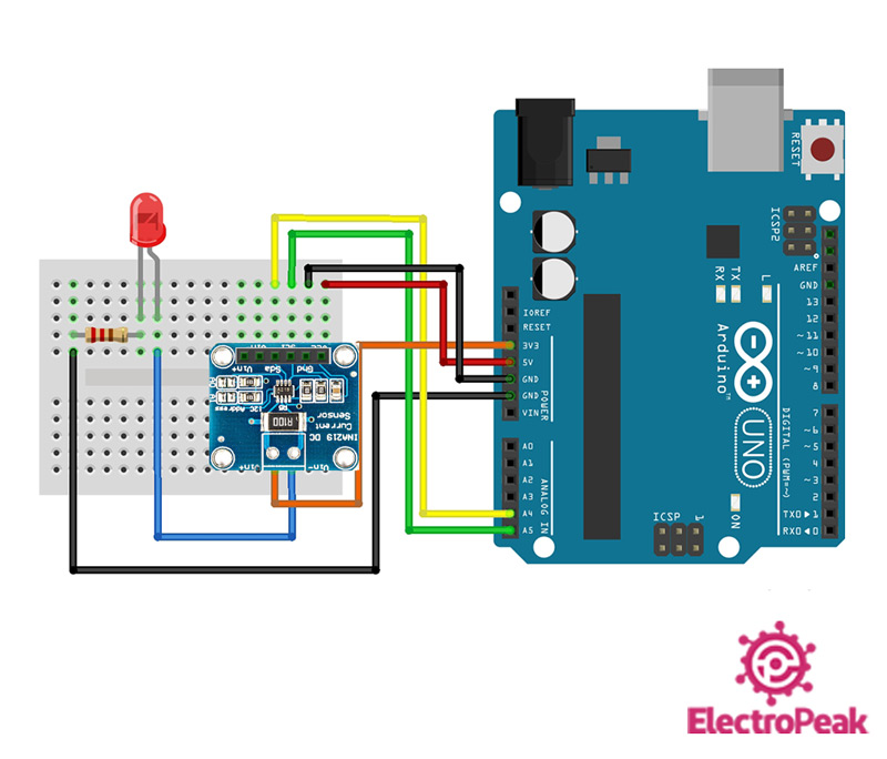
      First check the wiring to make sure all pins are correctly connected to each other. Especially SDA and SCL which must be connected to pins A4 and A5 respectively. If those 2 pins are not properly connected you might get an error like the one you’ve got now. Also, you can use the i2c_scanner in Arduino IDE File -> Examples -> Wire -> i2c_scanner to see if any I2C devices are found. If you still get no I2C scanner, there might be something wrong with the INA219 module itself.

      July 10, 2022 at 11:27 am
  • Nasrul Reply

    Shouldn’t it be “loadvoltage = busvoltage – (shuntvoltage / 1000)” instead of “loadvoltage = busvoltage + (shuntvoltage / 1000)”?

    December 19, 2022 at 7:35 am
  • Kevin Reply

    Dear Sir,
    I have followed your step and the voltage can not be shown on serial port monitor.
    only current is shown on moinitor.

    January 5, 2023 at 7:39 am
    • Ali Abdolmaleki Reply

      Hi sir,good day
      What exactly is your problem?
      you mean dont recevie any measurment or the range is wrong?

      March 1, 2023 at 6:58 am
  • Cary Vallance Reply

    Hi,

    I am wondering if it is possible to enable a digital output (high) on the Arduino when a specific threshold is reached? this could be used to drive an output and/or act as an alarm.

    Do you have any code for this type of function?
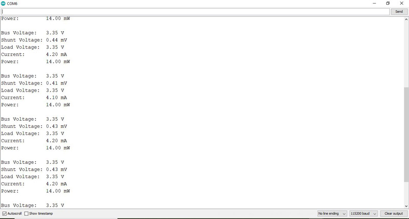
    January 6, 2023 at 5:16 pm
  • Abdelbari Benchine Reply

    Hello sir,
    Is it normal that after i followed your steps I got the lines above instead of values ? :

    �k������,��^���݊�����xV=���<��d�����i��6|d`<��.��^����,��^���h�Z
    h�X��.|�������,#��d�����ݲ�� �Y�i��2|� <�ݪ|��8���a�,+�xT����,��.��^���xT��_�,"��ѡ�,+��t�� �`��*|����� �$+��,��^���ݪ|��8��,��^����.|���xT����,���A�,#�Yt�[���.��^���Yt�[�,"���!�,+�i���|a`��.��^���i��2|� <�x�ZJ(�X �xT� ��,�i��2|`
    �h�04����.��^�����`�,+B�h��4<����.|��0���!�,+���!�$+�i��2<�@�x�Z��<��.��^����.��^���i��2|�`
    �ݪ|��8�xT����,�Yt�[�,"𝲌� ���i��2|d ��ݺ�� �����!aU�B�xT����,�xV=���<��.|��0�Xt�[�,"��t�� ���x����<��.��^������,#��t�� ����.��^���i��2|�`
    ��,��^����d�����Xt�[�,"�i���|a`�ݺ�� �Y�xT� ��,�i��2|�`<�h�$
    (�X�xT� ��,��xT����,�xT��_�,"�Yt��[��i��6|�
    �i��2<�@�ݪ�����i��2|“
    �h�$
    h�X���a�,+�i��2|d ��xt�[�,"�ݲ�� �Y��.|��A��xt� �<"X �i��2|` <��.��^���xT� ��,���`�,+�h�0<��`��.��^����� �,+�Yt�[��i��2|�
    ���� ���h��2<�@��.|����.��^���ݪ�����x�$J(X �ݢ|��8�xV= ��<��,��^����ѡ�,+�h�44��`�i��2|` <�ݪ|��8�h�Z
    (�X�xV�Z��<�i��6|d`��xT� ��,��ѡaU�B�Yt�[���d�����x���t 6�xV�Z��<�h�Z
    h�X󝲌� �Y�i��6|d`<�h�04��`�x�$H(X ���!�,+B����,#�h�0<�`�ݒ�8�xV=���<���!�,+�xV�Z��<�h�Z

    May 9, 2023 at 12:32 pm
    • Hadi Norouzi Reply

      Hi sir.
      You have got the wrong baud rate. You should adjust it at 115200

      May 13, 2023 at 10:43 am
  • Andhy Reply

    Hi Amir

    Very appreciate your posting here. I Have a question regarding the serial baudrate. Can we user lower baudrate ie: 9600 ? as im trying to connect the Arduino board to not only INA219 but other board also.

    Thanks in advance.

    Regards

    June 28, 2023 at 3:16 pm
    • Mohammad Damirchi Reply

      Hi
      To change the baud rate, simply write your desired speed in the line below.
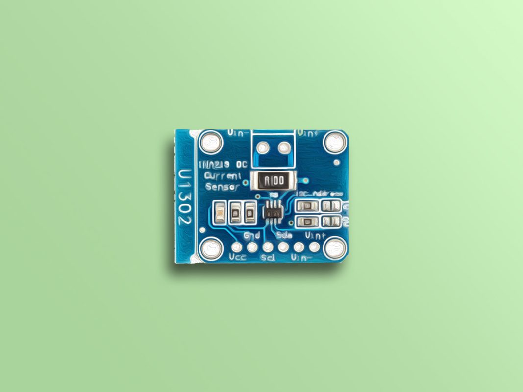
      Serial.begin(115200);

      July 1, 2023 at 6:04 am
  • Teena Reply

    Which software did you use to draw the circuit diagram in “Step 1: Circuit”? Did the software has INA219 listed in the component list?

    August 22, 2023 at 2:02 pm
    • Mohammad Damirchi Reply

      Hi Teena
      we used the Fritzing software to show the wiring. In addition, INA219 is not in the component list.
      If you want to design the PCB, you should use Proteus or Altium.

      August 23, 2023 at 4:38 am
  • Ryan99Alero Reply

    Hate to say I love it when someone try’s to correct someone and they end up being wrong… Thanks for example super simple logic. Was going to just use a Shunt resistor but with this I can do a little more. Plus get an idea of how fast I can move windows before considering it either shut or obstructed. Wanting to build a Smart module for my car windows for auto up and down but also want to throw on a canbus hat as well so I can control the windows on a touch display / automatically. Along with more easily control other locks and windows with minimal wiring over the canbus.

    August 26, 2023 at 1:58 am

Leave a Reply

Your email address will not be published. Required fields are marked *