
Product added to cart

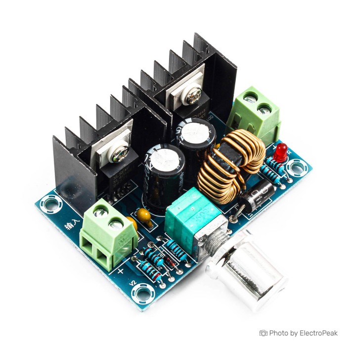
XL4016E1 DC/DC Step-Down Regulator Module
$1.7500
In stock
SKU
BAT-02-074
Volume discounts:
- +50 5 % $1.6600
- +100 7 % $1.6200
- +300 10 % $1.5700
- +500 13 % $1.5300
- +1000 15 % $1.4800
Ships in 2-3 business days, then:
Free delivery in 12-15 days by Tracked Economic Shipping on orders over $100.
Free delivery in 7-10 days by Express Shipping on orders over $300.
More shipping info

Shop with confidence Learn More
 DC-DC Step-Down Buck Power Module - 8-28V to 3.3V, 3A Previous
XL4016E1 8A Buck Module Review
The XL4016E1 DC/DC Step-Down Regulator Module is an adjustable PWM buck converter for reducing DC voltage in electronics and prototype power systems. With a DC 4–40V input range, it provides an adjustable DC 1.25–36V output with up to 8A maximum current and 200W maximum power. It suits makers stepping down 12V or 24V rails for DC motors, lighting arrays, or general bench supply tasks and comparing DC-DC regulator modules.
The board offers high current capacity in a compact footprint, but it needs deliberate thermal planning in real installations. Its 8A rating is an upper design ceiling, not a continuous fanless rating. Sustained high-current use requires active airflow and careful voltage adjustment before connecting a load.
Specifications of XL4016E1 DC/DC Step-Down Regulator Module
- Module type: DC voltage regulator
- Input voltage: DC 4-40V
- Output voltage range: DC 1.25-36V
- Maximum current: 8A
- Maximum power: 200W
- Efficiency: 94%
- Switching frequency: 180kHz
- Dimensions: 61 × 41 × 27 mm
XL4016E1 Specifications and Limits
This module works strictly as a step-down regulator. Its output voltage cannot exceed or match the incoming supply, so reliable regulation requires an input voltage higher than the selected output. Although the board accepts DC 4–40V input, the underlying XL4016E1 IC datasheet recommends an 8–40V operating window for rated electrical performance. Input below 8V can limit load capability and regulation stability under heavier current demands.
| Specification | Stated Value | Real-World Design Consideration |
|---|---|---|
| Input Voltage | DC 4–40V | Allows integration with standard 12V and 24V rails. Plan for 8–40V when designing for rated output performance. |
| Output Voltage Range | DC 1.25–36V | Adjustable via onboard potentiometer. Must be adjusted and verified with a meter before connecting any load. |
| Maximum Current | 8A | Ceiling rating. Sustained 5–8A operation generates substantial heat and requires active forced-air cooling. |
| Maximum Power | 200W | Product of output voltage and load current. Both the 8A and 200W ceilings must be respected simultaneously. |
| Efficiency | 94% | Peak best-case figure. Typical efficiency sits near 93% at 24V-to-12V at 6A, dropping toward 87% at 12V-to-5V at 6A. |
| Switching Frequency | 180kHz | Standard fixed frequency. Generates switching ripple (typically 50–100mV on common revisions) requiring extra filtering for analog rails. |
| Dimensions | 61 × 41 × 27 mm | Physical clearance profile needed for standoffs, enclosure depth, and unobstructed heatsink airflow. |
Thermal dissipation sets the real operating limits of this high-current buck converter. Under natural convection without forced air, thermal saturation limits safe continuous operation to roughly 5A. From 5A to the 8A maximum, onboard components heat rapidly. Use direct fan airflow or additional heatsinking across thermal pathways to prevent thermal stress.
Generic multi-OEM production also brings several hardware limitations. Output ripple in the 50–100mV range makes this module unsuitable for precision analog, audio, or sensitive RF circuitry without a secondary LC filter or low-noise linear post-regulator. On many revisions, the onboard trimmer is sensitive across a single turn, so millimeter adjustments can produce noticeable voltage steps. Reverse-polarity protection is not universally implemented across board revisions, while overcurrent or thermal shutdown behavior stems from the IC architecture rather than an individually certified system-level assembly. For DC inputs higher than 40V, consider a high-voltage 53V buck converter instead.
XL4016E1 Accessories and Power Requirements
This module needs external hardware for input power, interconnections, thermal management, and circuit verification. As a bare-board module, it requires connection leads and operating hardware matched to your target current draw.
Required Accessories
- DC Input Source: Use a clean DC power source within the DC 4–40V range (8–40V recommended for rated loads). For basic bench testing and loads up to 2A, a 12V 2A DC input supply is a stable starting point, though it cannot drive the module to its higher current capabilities.
- High-Current Wiring and Connectors: Use solder leads or screw-terminal wires sized to carry up to 8A safely, without excessive resistive voltage drops or insulation heating.
- Multimeter: A digital multimeter is needed to measure terminal output voltage before connecting sensitive electronics.
Recommended Accessories
- Active Airflow or Cooling Hardware: Use a DC cooling fan or an aluminum heatsink to improve heat transfer during sustained currents between 5A and 8A.
- Prototyping Interconnects: A prototype jumper wiring kit works for control signals and low-current breadboard testing under 1A. These thin wires must never carry high-current loads.
- Output Filter: Add an external LC low-pass filter or low-ESR bulk capacitors to smooth switching ripple when supplying microcontrollers or sensor nodes.
Optional Additions
- External Multi-Turn Potentiometer: This replaces a sensitive single-turn onboard trimpot for fine millivolt-level output tuning.
- Series Polarity Protection Diode or MOSFET: Place this at the DC input to prevent board destruction if the wiring is reversed.
- Ventilated Enclosure: Use a dedicated housing with inlet and exhaust vents to support steady convective or forced airflow during continuous adjustable DC power conversion.
XL4016E1 Setup, Wiring, and Output Adjustment
The XL4016E1 is a purely analog DC regulator module, so it needs no software, firmware, or device drivers. Correct operation depends entirely on proper wiring polarity, accurate initial calibration, and respecting physical limits.
- Check Input Polarity: Verify the positive and negative leads of your DC power supply with a multimeter. Reverse-polarity protection is not confirmed for this module revision, and reversing the input leads can destroy the regulator.
- Connect the DC Supply: Connect the positive lead to IN+ and the ground lead to IN− using appropriately gauged wire. Ensure the supply voltage is between DC 4V and 40V.
- Probe the Output: Place multimeter test leads across OUT+ and OUT− with the meter set to DC voltage. Do not connect the intended load yet.
- Set Output Voltage: Power on the input supply. Turn the adjustment potentiometer while watching the meter until the output reaches your target level between DC 1.25V and 36V. Module revisions with single-turn trimpots are sensitive, so adjust slowly and monitor continuously. If fine tuning is your main design priority, a 25-turn adjustable buck converter provides finer adjustment granularity.
- Connect the Load: Power off the input supply, connect the load to OUT+ and OUT−, then power the system back on. Confirm that total load current remains under 8A and power remains below 200W.
- Monitor Thermal Rise: Check the operating temperature during the first 15 minutes of operation. Provide active fan cooling if the load continuously draws 5A or more. Use prototype jumper wiring only for lightweight logic bench tests, switching to heavy copper wire for real loads.
If the output fails to regulate, check these common first-time setup errors: input voltage below the required dropout margin relative to the output, reversed input polarity, or excessive load current triggering thermal protection shutdown.
XL4016E1 vs XL4015 and LM2596 Buck Converters
Your input voltage ceiling, load current, and adjustment requirements determine the right step-down module. The table compares the XL4016E1 with common alternative DC-DC step-down and step-up modules using only their verified specifications.
| Module | Input Voltage | Output Voltage | Max Current | Max Power | Switching Frequency |
|---|---|---|---|---|---|
| XL4016E1 | DC 4–40V | DC 1.25–36V | 8A | 200W | 180kHz |
| XL4015 Step-Down Regulator Module | 8–36V (38V max) | 1.25–32V | 5A | 75W | 180kHz |
| XL4005 Buck Converter | 5–32V | 0.8–30V | 5A | Not stated | 300kHz |
| LM2596 3A Buck Converter | 4.5–40V | 1.5–35V | 3A | 15W | 150kHz |
| LM2596HVS High-Voltage 3A Buck Converter | 4.5–53V | 3–40V | 3A (2A typical) | 15W | 150kHz |
| XL6009 Step-Up Boost Module | 4–32V | 5–35V | 4A | Not stated | 400kHz |
For mid-power designs needing up to 5A, the XL4015 5A step-down module has a smaller board footprint and is capped at 75W. Need low-voltage regulation down to 0.8V or precision multi-turn trimmer control? The XL4005 is a viable alternative. For low-current microcontrollers and logic rails under 3A and 15W, the LM2596 3A buck converter is a compact, low-cost option. Where DC input exceeds 40V, such as on 48V battery systems, the LM2596HVS accepts inputs up to 53V. If the system needs to step voltage up rather than down, the XL6009 boost converter uses an entirely different topology to increase voltage.
XL4016E1 8A Buck Module FAQ
Can the XL4016E1 8A buck module run 8A continuously without a fan?
No. Running 8A continuously without active forced-air cooling causes severe thermal buildup. The 8A rating is an absolute maximum; in still air, continuous operation should be limited to approximately 5A. For continuous currents between 5A and 8A, provide dedicated fan airflow across the module's heatsinks.
What input voltage can the XL4016E1 DC/DC Step-Down Regulator Module accept?
The module accepts DC 4–40V input. For rated high-current performance, the XL4016E1 IC datasheet recommends maintaining an input between 8V and 40V. The input must always be higher than the target output voltage.
Can this XL4016E1 module increase voltage?
No. The XL4016E1 is strictly a step-down buck converter that lowers voltage. For raising a lower DC supply to a higher level, use a step-up boost converter such as the XL6009.
Why is the XL4016E1 output voltage hard to set precisely?
Common module builds use a single-turn potentiometer, where a small mechanical rotation covers a large voltage swing. Measure across the output terminals with a multimeter while making tiny, deliberate adjustments. For permanent setups requiring exact target voltages, replacing the trimmer with a multi-turn potentiometer resolves this sensitivity.
Does this XL4016E1 module include reverse-polarity protection?
Reverse-polarity protection is not specified for this listing and varies across OEM board versions. Confirm input lead polarity with a meter before powering the module, or wire an external reverse-polarity diode in series with the input line.
Is XL4016E1 the same as XL4015?
No. They use different regulator ICs with distinct ratings. The XL4016E1 is rated for up to 8A and 200W, while the XL4015 is rated for a maximum of 5A and 75W with a slightly narrower voltage envelope.
Is this XL4016E1 module suitable for battery charging or constant-current LEDs?
No. This listing specifies a constant-voltage adjustable step-down regulator without constant-current (CC) control circuitry. Specialized CC/CV variants of the XL4016E1 family exist, but this module regulates voltage only and should not be used as a standalone lithium battery charger or direct LED current limiter. For other specialized power conversion tasks, browse other DC-DC converter options.
Purchase Decision Summary
- Ideal for: Stepping down DC 12V or 24V power sources to lower voltages between 1.25V and 36V for motors, actuators, relays, and general DC electronics where up to 8A is needed and airflow can be provided.
- Maybe for: Adjustable DIY bench power supply projects, provided you measure output before connecting loads and can tolerate 50–100mV switching ripple.
- Consider another option if: Your application needs voltage boost conversion, fanless continuous 8A current in a sealed box, constant-current battery charging, ultra-low-noise analog supply rails, or verified reverse-polarity protection.
Buying Checklist
- Verify that your input power source is DC and remains within the DC 4–40V range (8–40V preferred for heavy loads).
- Confirm that your required output voltage is lower than the input supply and falls between DC 1.25V and 36V.
- Ensure your total continuous load does not exceed 8A or 200W.
- Plan for active cooling (a DC fan) if your continuous load exceeds 5A.
- Confirm you have a multimeter available to tune the output trimmer before connecting sensitive circuits.
- Source appropriately rated copper wire for high-current input and output connections.
- Check that your project enclosure can accommodate the module's 61 × 41 × 27 mm footprint with adequate ventilation.
Write Your Own Review

Please complete your information below to login.
Sign In
Create New Account