
Product added to cart

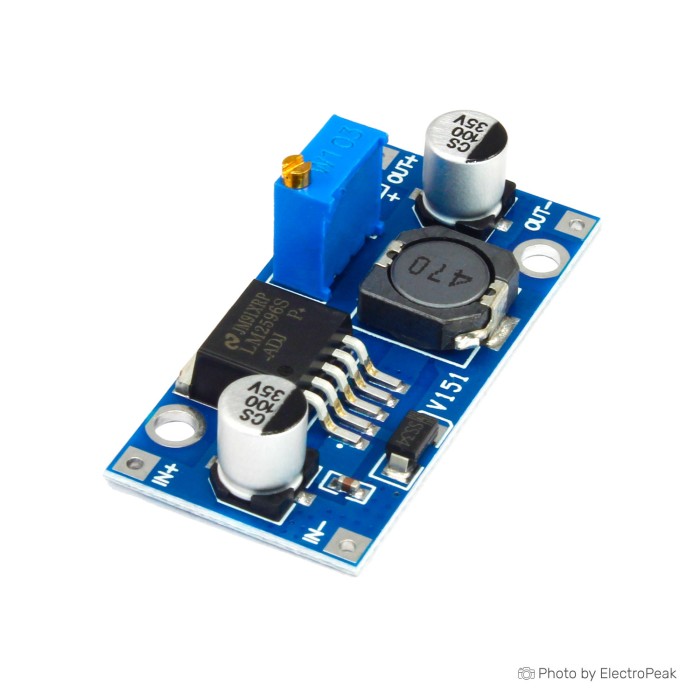
LM2596 DC-DC Step Down Power Supply Module -Buck Converter
$0.5900
In stock
SKU
BAT-02-031
Volume discounts:
- +50 3 % $0.5700
- +100 5 % $0.5600
- +300 7 % $0.5500
- +500 8 % $0.5400
- +1000 10 % $0.5300
Ships in 2-3 business days, then:
Free delivery in 12-15 days by Tracked Economic Shipping on orders over $100.
Free delivery in 7-10 days by Express Shipping on orders over $300.
More shipping info

Shop with confidence Learn More
 10A 600W DC-DC Adjustable Boost Converter Step Up Voltage Regulator Module Previous
LM2596 Buck Module Review
The LM2596 DC-DC Step Down Power Supply Module is an adjustable switching regulator that converts a higher DC input voltage into a stable, lower DC output. Built around step-down (buck) topology, it suits hobby, educational, prototyping, and low-power microcontroller supply tasks. Heat is the main operating constraint: as the gap between input and output voltage widens or load current rises, heat generation increases and limits sustained throughput.
Comparable generic-market modules sell between $0.60 and $3.50 each, depending on source and quantity. That makes this board an accessible option among DC-DC regulator modules for bench experiments and simple embedded power rails.
Specifications of LM2596 DC-DC Step Down Power Supply Module
- Type: Step-Down Voltage Regulator Module
- Model: LM2596
- Maximum Output Current: 3A
- Input Voltage Range: 4.5V to 40V DC
- Output Voltage Range: 1.5V to 35V DC (Adjustable)
- Output Power: 15W maximum
- Adjustable Output: Yes
- Efficiency: Typically 92% (depends on input/output voltage difference and load)
- Switching Frequency: Typically 150 kHz
- Size: 43mm x 21mm x 14mm L x W x H
- Protection Features: Over-temperature, Over-current, Short Circuit Protection (Some models may have these features)
- Output Ripple: Typically 30mV (varies by model)
- Operating Temperature Range: -40°C to +85°C (varies by model)
- Connection: Pads for Input and Output
- Cooling Method: Natural convection (no built-in fan)
- Mounting: Screw holes for secure attachment
- Conversion Type: Step-Down (Buck)
LM2596 Buck Module Specifications Explained
These ratings determine how the module fits into a circuit and whether it can operate reliably within the required tolerances.
| Specification | Listed Value | Why It Matters in Practice |
|---|---|---|
| Conversion Type | Step-Down (Buck) | The board can only reduce voltage. The input voltage must always remain higher than the target output voltage by roughly 1.5V to account for dropout voltage. |
| Input Voltage Range | 4.5V to 40V DC | Accommodates common DC rails such as 9V, 12V, 24V, or 36V. For DC sources that exceed 40V, the high-voltage LM2596 step-down module accepts up to 53V DC. |
| Output Voltage Range | 1.5V to 35V DC (Adjustable) | Lets you set standard logic voltages such as 3.3V, 5V, or 12V with the onboard multi-turn trimmer before powering the downstream circuit. |
| Connection Method | Pads for Input and Output | Requires direct wire soldering or soldered header pins. Flexible jumper wires for module connections work well for bench testing, but permanent installations require direct solder joints. |
| Form Factor & Mounting | 43mm x 21mm x 14mm with screw holes | The compact footprint fits small project enclosures, while the pre-drilled corner holes support mechanical standoff mounting to isolate solder joints from conductive surfaces. |
| Cooling Method | Natural convection (no built-in fan) | Heat transfers directly from the IC tab into the board copper and surrounding air. Without forced air, sustained high current leads to rapid heat accumulation. |
| Protection Features | Some models may have over-temperature, over-current, short circuit protection | Protection circuitry varies by manufacturing batch and is not universally guaranteed. External fusing and verified wiring polarity remain essential in any design. |
Across the broader range of DC-DC regulator modules, verify that the source voltage leaves enough operating headroom above the target output under lowest-battery or loaded-supply conditions.
LM2596 3A Buck Converter Limits and Heat
The module has a 3A maximum output current rating and a 15W maximum output power rating. These figures are peak operating limits, not blanket continuous-load specifications. Generic unheatsinked boards under natural convection handle continuous loads around 1.5A to 2A safely. Sustained current above that range makes the regulator IC and surrounding components run hot, eventually causing thermal throttling or output-voltage instability.
Thermal dissipation depends directly on the difference between input and output voltage. Stepping 12V down to 5V at 1.5A produces modest warmth. Stepping 36V down to 5V at the same 1.5A forces the switching elements and freewheeling diode to manage substantially higher losses, raising temperatures rapidly. While efficiency is listed at typically 92%, that figure reflects favorable input-to-output ratios; efficiency drops under wide voltage deltas and near maximum load limits.
Output ripple is listed at typically 30mV, though it varies across board revisions and load profiles. It is clean enough for digital microcontrollers, logic gates, and relay coils, but this ripple level may introduce noise into sensitive analog sensors, operational amplifiers, or RF communication stages unless secondary LC filtering is added.
Do not make these three assumptions about this board:
- Do not assume continuous 3A delivery without active cooling or heatsinking.
- Do not assume a flat 92% efficiency across all conversion ratios.
- Do not assume short-circuit or reverse-polarity protection will prevent damage during wiring errors.
Unbranded modules can also show internal component variance between production runs. Some batches may substitute alternative inductor cores or switching ICs that cycle near 50 kHz rather than the standard 150 kHz LM2596 frequency, leading to higher output ripple. For applications requiring sustained 3A to 5A output, the XL4015 5A step-down module is a heavier-duty alternative rated up to 75W. Near the upper thermal boundaries of the LM2596, adding a small aluminum heatsink directly to the IC package helps dissipate excess heat.
LM2596 Buck Module Uses and Compatibility
The LM2596 module fits hobbyist setups, embedded prototypes, and distributed low-voltage systems where an existing DC bus needs local step-down regulation. Common uses include stepping 12V down to 5V for dev boards, running 3.3V logic from an 11.1V lithium-polymer battery, or powering 12V LED strips from a 24V industrial rail.
The table below summarizes compatibility across common design environments:
| System Element | Compatibility Status | Integration Rules |
|---|---|---|
| Input Source | Compatible (DC only) | Requires clean 4.5V to 40V DC. A standard 12V 2A DC power supply provides an ideal input source for 5V microcontroller builds. Direct AC mains or raw transformer secondaries must not be connected. |
| Logic & Microcontrollers | Compatible | Powers boards such as Arduino, ESP32, or sensor networks once the output is preset to 3.3V or 5.0V before connection. |
| Variable Input Supplies | Conditional | If the input source drops below the target output, such as a discharging battery pack, output regulation fails. Systems with fluctuating supplies require an automatic buck-boost module instead. |
| Multiple Output Rails | Single rail only | This module supplies only one regulated voltage. Projects requiring distinct simultaneous rails (e.g., 3.3V, 5V, and 12V) need multiple boards or a multi-output supply. |
| High-Power Motors & CC Loads | Not recommended | Lacks constant-current control; unsuitable for direct high-power bare LED driving or heavy inductive motor stall currents. |
For other conversion topologies or multi-rail power trees, see the available DC-DC regulator modules.
LM2596 Buck Converter Alternatives
Where system requirements exceed single-channel step-down limits, these pin- and function-specific alternatives address different needs:
| Module | Conversion Type | Input Range | Output Range | Max Current / Power | Key Distinguishing Trait |
|---|---|---|---|---|---|
| LM2596 (Standard) | Step-Down (Buck) | 4.5V–40V DC | 1.5V–35V DC | 3A / 15W max | Compact, single-channel bare board with solder pads. |
| LM2596 module with onboard voltage display | Step-Down (Buck) | 4.5V–40V DC | 1.5V–35V DC | 3A / 15W max | Integrated 3-digit LED display for real-time voltage monitoring. |
| high-voltage LM2596 step-down module | Step-Down (Buck) | 4.5V–53V DC | 3V–40V DC | 3A / 15W max | Extended input tolerance for up to 48V nominal systems. |
| LM2596HV AC/DC and DC/DC step-down option | Step-Down (Buck) | 5V–30V AC / 5V–50V DC | 3.3V–33V DC | 2.2A continuous (3A peak) | Includes rectifier bridge and mounted heatsink for AC or DC input. |
| XL4015 5A step-down module | Step-Down (Buck) | 8V–36V DC | 1.25V–32V DC | 5A / 75W max | Substantially higher current capability and higher switching frequency. |
| LM317 linear regulator module | Linear Step-Down | 4.2V–40V DC | 1.2V–37V DC | 1.5A max | Linear conversion provides low electrical noise at the cost of heat efficiency. |
| dual-channel LM2596 step-down module | Dual Step-Down | 5V–40V DC | 1.25V–35V DC (x2) | 2.5A cont. / 20W per channel | Two independently adjustable outputs with a shared input bus. |
| four-channel LM2596 step-down module | Quad Step-Down | 5V–35V DC | 4 independent outputs | 5A total output | Provides four distinct output rails on a single 115x65mm PCB. |
| XL6009 step-up boost module | Step-Up (Boost) | 4V–32V DC | 5V–35V DC | 4A max | Increases lower input voltages to higher output levels. |
| automatic buck-boost module | Buck-Boost | 5V–32V DC | 1V–30V DC | 10A / 80W cont. | Maintains regulated output whether input rises above or falls below target. |
LM2596 Buck Module Setup and Accessories
Set the output voltage before connecting sensitive electronics. The onboard potentiometer is a multi-turn trimmer, so it may need ten or more counter-clockwise rotations before the output voltage begins to drop below the input level.
- Confirm that the input voltage source falls within 4.5V to 40V DC.
- Connect the positive and negative leads of the power source to IN+ and IN- pads. Verify polarity carefully; reverse polarity protection is not specified and incorrect connections can destroy the board.
- Power on the input source with no load connected to OUT+ and OUT-.
- Place multimeter probes across OUT+ and OUT- set to DC voltage measurement.
- Turn the brass trimmer screw on the potentiometer until the multimeter displays your desired output voltage.
- Disconnect input power, solder your load wiring to the OUT+ and OUT- pads, then reapply power.
- Verify that the output voltage remains stable under load, and check board temperature after several minutes of run time.
Required Accessories
- DC Power Source: Must supply 4.5V to 40V DC at adequate amperage. A 12V 2A DC power supply suits bench testing and low-power 5V regulation.
- Connection Wiring: Solid copper hookup wire or a jumper wire kit for module connections to carry power between the source, module pads, and prototype load.
- Digital Multimeter: Required to measure and calibrate the output voltage before connecting downstream devices.
Recommended Accessories
- Heatsink: An adhesive-backed small aluminum heatsink mounted to the switching IC provides thermal margin when current exceeds 1.5A or when managing large voltage differentials.
- Inline Fuse or Protection Diode: Place it in series with the IN+ terminal to safeguard against overcurrent and accidental reverse-polarity events.
- Enclosure & Standoffs: Use non-conductive mounting hardware to secure the board through its screw holes and maintain airflow.
Optional Additions
- Output Filter: An external low-ESR capacitor or LC filter stage can reduce switching ripple for noise-sensitive analog circuitry.
- Integrated Display Board: For builds that require frequent adjustment without attaching a meter, the LM2596 module with onboard voltage display provides real-time readouts on the board.
LM2596 Buck Module FAQ and Buying Checklist
What is the LM2596 buck module used for?
The LM2596 buck module steps a higher DC voltage down to a lower, stable DC voltage. It functions only as a buck converter, so it can lower voltage but not raise it.
Can this LM2596 module convert 12V to 5V?
Yes. Converting 12V DC down to 5V DC is one of the most common applications for this board. A 12V source sits comfortably within the 4.5V–40V input range, and 5V falls within the 1.5V–35V adjustable output limits.
What is the real continuous current limit of this 3A buck converter?
In standard natural-convection environments without a heatsink, the practical continuous limit is roughly 1.5A to 2A. Although the IC is rated for 3A peak maximum, continuous operation near 3A causes thermal saturation unless active airflow or external heatsinking is applied.
Why does an LM2596 buck module get hot when stepping 24V or 36V down to 5V?
Wide input-to-output differentials increase switching and conduction losses across the regulator and diode. Even at modest current draws, wide voltage drops generate substantial heat that natural convection alone struggles to shed.
How do I adjust the LM2596 output voltage?
Turn the small brass screw on top of the blue potentiometer while measuring the output pads with a digital multimeter. The potentiometer uses a multi-turn mechanism, so it may take 10 to 15 full counter-clockwise rotations before the voltage begins dropping.
Does this LM2596 buck converter have short-circuit or reverse-polarity protection?
Protection features vary by manufacturing batch and are not guaranteed across all generic units. Reverse-polarity protection is not included, and short-circuit protection should not be relied on to save the board from hard faults.
Do I need a heatsink for this LM2596 module?
A heatsink is strongly recommended when your continuous load exceeds 1.5A or your input voltage is significantly higher than your output voltage. Under light loads below 1A with modest voltage drops, natural convection cooling is sufficient.
When should I choose the XL4015 5A Step-Down Module instead?
Choose the XL4015 5A step-down module when continuous current demands exceed 2A or total output power exceeds 15W. Its 5A / 75W rating provides greater headroom for heavier loads.
Purchase Decision Summary
- Ideal for: Stepping down 9V, 12V, or 24V rails to 3.3V or 5V for microcontrollers; prototype bench setups; low-power logic projects drawing under 1.5A.
- Maybe for: Loads drawing between 1.5A and 2.5A if an auxiliary heatsink and good enclosure ventilation are provided.
- Avoid if: Your input voltage can fall below your desired output; you require continuous 3A+ throughput; your project requires guaranteed low ripple for precision audio/RF; or you need documented component traceability.
Buying Checklist
- The power source is DC (not AC) and provides between 4.5V and 40V.
- The target output voltage is lower than the input source by at least 1.5V.
- The continuous load current is below 2A, or supplemental cooling is planned.
- A digital multimeter is available to adjust the output voltage before connecting the load.
- Soldering equipment and hookup wires, such as jumper wires for module connections, are on hand for the pad terminals.
- A single output rail meets system requirements, or you have reviewed alternative multi-rail DC-DC regulator modules.
Write Your Own Review

Please complete your information below to login.
Sign In
Create New Account