
Product added to cart

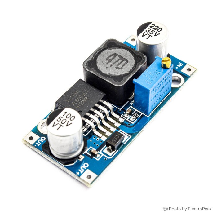
XL6009 DC/DC Step-up Boost Power Supply Module
$0.6100
In stock
SKU
BAT-02-047
Volume discounts:
- +50 5 % $0.5800
- +100 7 % $0.5700
- +300 8 % $0.5600
- +500 11 % $0.5400
- +1000 13 % $0.5300
Ships in 2-3 business days, then:
Free delivery in 12-15 days by Tracked Economic Shipping on orders over $100.
Free delivery in 7-10 days by Express Shipping on orders over $300.
More shipping info

Shop with confidence Learn More
 ATX PSU Power Supply Module - 160W, 12V Previous
XL6009 Boost Module Review and Specifications
The XL6009 DC/DC Step-Up Boost Power Supply Module is an adjustable switching regulator that raises a lower direct-current input voltage to a higher direct-current output voltage. It suits low-to-moderate-power prototype rails, bench experiments, and custom electronics where the output voltage remains strictly above the input level. Projects requiring guaranteed 4A continuous output current, built-in lithium battery charging management, galvanic isolation, or automatic step-down behavior need a different power topology or a larger converter from our DC-DC regulator modules catalog.
Specifications of XL6009 DC/DC Step-up Boost Power Supply Module
- Model: XL6009
- Load regulation: ±0.5%
- Voltage regulation: ±0.5%
- Input voltage: 4 - 32 volts
- Maximum input current: 4A
- Output voltage: 5 to 35 volts
- Maximum output current: 4A
- No-load current at 5V input and 8V output: 18 mA
- Switching frequency for XL6009: 400KHz
- Switching frequency for LM2577: 150kHz
- Operating temperature: 40- to 85+ degrees Celsius
- Dimensions: 43mm * 21mm * 12mm
- Conversion efficiency: 92% (Max.)
XL6009 Boost Module Specifications Explained
A step-up switching converter stores energy in an inductor, then releases it into an output capacitor at a higher voltage. Knowing how the published ratings translate to bench performance helps prevent wiring mistakes and component damage.
| Specification | Listed Value | Why It Matters in Practice |
|---|---|---|
| Input Voltage Range | 4 - 32 volts | The source must maintain at least 4V under full operating load. Because this is a boost-only topology, the input must remain lower than the intended output at all times. |
| Output Voltage Range | 5 to 35 volts | The multiturn potentiometer sets any continuous target rail in this span. Adjust and confirm the set voltage with a multimeter before attaching sensitive electronics. |
| Maximum Efficiency | 92% (Max.) | Peak efficiency occurs only under optimal input-to-output voltage ratios at moderate currents. As the boost ratio widens, switching and conduction losses increase and generate onboard heat. |
| No-Load Current | 18 mA (at 5V in, 8V out) | The internal control circuitry consumes standby power even with no load attached. In sleep-mode or continuously battery-operated devices, this idle consumption drains cells over time. |
| Switching Frequency | 400KHz | A 400kHz switching rate allows the board to use a compact inductor while maintaining ±0.5% voltage regulation on resistive loads. |
| Board Dimensions | 43mm * 21mm * 12mm | The compact footprint fits standard project boxes and breadboard arrangements, but mechanical clearance is still needed for wire termination and screwdriver access to the adjustment screw. |
When enclosure space is the overriding constraint in a small, lower-power build, the MT3608 2A Boost Module offers a smaller 14 × 17 × 36 mm footprint and an input range starting at 2V. For XL6009 bench prototypes, standard prototype wiring can be soldered directly to the corner through-hole pads.
XL6009 Boost Module Limitations and 4A Output Reality
The specifications list a maximum input current of 4A and a maximum output current of 4A. In any boost converter, however, output current is physically constrained by energy conservation and conversion losses:
Input Power = (Output Power / Efficiency)
Since the input voltage is lower than the output voltage, input current is always higher than load current. A circuit stepping up 5V to 24V for a 1A load (24W) draws over 5.6A from the 5V source at 85% efficiency. That exceeds the 4A input limit of the switch before the load approaches 4A.
No continuous output-power curve, thermal derating data, or validated continuous high-current test conditions are established for this board. High sustained current causes rapid thermal buildup in the switching IC, inductor, and catch diode. An optional heatsink after thermal validation can conduct heat away from the primary IC package, but it will not overcome the inductor's magnetic saturation limits or the board's input current threshold.
The controller provides switch-level current-limiting support, protecting the internal transistor against momentary peak saturation. It is not an adjustable constant-current driver or a battery charge-termination circuit. It cannot regulate current for high-power LED arrays or safely charge lithium cells. Inductive loads such as DC motors, solenoids, or large uncharged capacitor banks produce massive startup surges that can trip current limits or unexpectedly drop the output voltage.
For continuous delivery above 15W to 20W, the higher-power boost module with onboard voltage display carries a documented 75W to 128W rating. Where true current regulation is required, the constant-current high-power boost module provides independent voltage and current adjustment potentiometers up to 8A.
XL6009 Boost Module Compatibility and Wiring Requirements
The XL6009 is a non-isolated DC-to-DC converter. The negative input terminal (IN−) and negative output terminal (OUT−) share a common electrical path across the PCB plane. Do not use this module where ground loops must be avoided or where input-to-output galvanic isolation is legally or functionally required.
| System Element | Module Requirement | Integration Consideration |
|---|---|---|
| DC Input Source | 4V to 32V DC stable supply | Must supply the full calculated input current plus startup transient margins without dropping below 4V. |
| Output Rail | 5V to 35V DC adjustable | Boost target must always be configured higher than the highest expected input voltage. |
| Load Compatibility | Resistive or low-inrush electronics | Loads with high inrush (motors, relays, high capacitance) need soft-start or external margin testing. |
| Control Interface | Analog trimmer only | No microcontroller drivers, software libraries, firmware, or digital communication buses are involved. |
| Safety Protections | External fusing required | No input reverse-polarity diode is present. Reverse input polarity destroys the switching controller instantly. |
For a validated battery input source, calculate whether the cell discharge voltage will fall below 4V. Single 3.7V nominal lithium-ion cells operate between 3.0V and 4.2V, so their lower voltage boundary falls below this board's reliable minimum input threshold.
To reduce a higher voltage source to a standard level, use a dedicated buck converter for stepping voltage down. For automotive rails or discharging multi-cell batteries where the source voltage can rise above and fall below the target output, use automatic buck-boost regulation for fluctuating input voltage instead of a boost-only board.
XL6009 Boost Module Setup and Voltage Adjustment
The output voltage is set manually with a multiturn trimmer, so improper setup can apply excessive voltage to connected electronics. Follow this bench validation sequence before wiring any permanent circuit.
- Visual Inspection: Inspect the solder joints and confirm terminal polarity markings on the board. Confirm that no solder bridges exist between IN+, IN−, OUT+, and OUT−.
- Source Connection: Connect a benchtop DC power supply set between 4V and 32V to IN+ and IN−. Use current limiting on your bench supply during initial power-up if available. Double-check wire polarity.
- Initial Metering: Leave the load completely disconnected. Set a multimeter to DC voltage mode and place its probes across the OUT+ and OUT− terminals.
- Potentiometer Adjustment: The trimmer is a multiturn screw. Counterclockwise potentiometer rotation increases output voltage, while clockwise rotation decreases output voltage. Because trimmer orientation can vary across production runs, watch the multimeter display rather than relying strictly on turn counts.
- Resolve Matching Voltage: If the measured output exactly equals your input voltage, the trimmer wiper is dialed below the input threshold. Turn the screw counterclockwise for 10 to 20 full revolutions until the voltage begins climbing above the input.
- Load Validation: Once the desired output voltage is established, power down the input supply. Connect your load, power the system back on, and observe the output voltage under load to confirm that the rail remains stable and the module stays within acceptable operating temperatures.
For compact 5V setups that use standard cable connections rather than raw wire leads, a Micro USB-powered boost module removes the need for manual input wiring in small desktop projects.
XL6009 Boost Module Alternatives for High Power, USB, and Variable Input
Regulator topology depends directly on your source voltage range, maximum current demand, and mechanical layout constraints. Use the comparison below to identify the appropriate unit for your circuit requirements.
| Model | Topology | Input Voltage | Output Voltage | Key Differentiator |
|---|---|---|---|---|
| XL6009 Boost Module | Step-up (Boost) | 4V – 32V | 5V – 35V | Compact 43 × 21 mm manual trimmer board for basic step-up rails. |
| MT3608 2A Boost Module | Step-up (Boost) | 2V – 24V | Up to 28V | Ultra-compact form factor for low-power, space-restricted enclosures. |
| MT3608 with Micro USB | Step-up (Boost) | 2V – 24V (or USB) | Up to 28V | Convenient 5V Micro USB socket input for quick prototyping. |
| LTC1871 100W Boost Module | Step-up (Boost) | 3V – 35V | 4V – 40V | Published 75W–128W rating with an integrated red digital voltmeter. |
| 250W Step-Up Module | Step-up (Boost) | 8.5V – 48V | 10V – 50V | High-power design with dedicated 0.2A–8A constant-current control. |
| LM2596 Buck Converter | Step-down (Buck) | 4.5V – 40V | 1.5V – 35V | Dedicated step-down conversion when input voltage is higher than output. |
| LTC3780 Stabilizer | Buck-Boost | 4V – 32V | 0.8V – 28V | Maintains steady output regardless of whether input is higher or lower. |
XL6009 Boost Module FAQ and Buying Checklist
Frequently Asked Questions
Is this really a 4A output XL6009 boost converter?
The board lists a 4A maximum output current, but continuous output capacity depends entirely on input voltage, output voltage, and operating heat. Boost circuits draw more current at the input than they deliver at the output, so wide step-up ratios reduce continuous safe current to substantially lower values.
Can this XL6009 step-up converter make 5V from a 12V battery?
No. A boost converter only increases voltage. When the input voltage exceeds the desired setpoint, current flows through the internal diode directly to the output without regulation. Use a step-down buck module for 12V to 5V conversions.
Can I use the XL6009 boost module with one 3.7V Li-ion cell?
Reliable operation is not guaranteed with a single 3.7V lithium cell. The published input range begins at 4V, above the 3.0V to 3.7V discharge range of lithium cells under load. Use a boost converter specified down to 2V or 3V for single-cell projects.
Does current limiting support mean it can charge lithium batteries?
No. The module provides internal switch-level protection to avoid component destruction, not an adjustable constant-current charge controller. Charging lithium chemistries without proper constant-current/constant-voltage curves and automatic termination creates an extreme safety hazard.
Why is my XL6009 output the same as the input voltage?
This happens when the multiturn trimmer wiper is set below your source voltage. Because boost converters pass DC through their inductor and diode, the meter reads the source voltage minus a diode drop until you turn the potentiometer counterclockwise enough to raise the setpoint.
Which way do I turn the XL6009 potentiometer to increase voltage?
Rotating counterclockwise increases the output voltage, while clockwise decreases it. Because potentiometer orientations can vary, always measure across OUT+ and OUT− with a multimeter while turning the adjustment screw.
Is the XL6009 boost module isolated?
No. This board shares a common ground between input and output and does not provide galvanic isolation. Do not use it in floating or isolated power architectures.
Do I need software or a driver for this boost converter?
No. The XL6009 is an entirely hardware-based analog switching power supply. It requires no drivers, software, firmware, or digital configuration.
What should I choose if my input voltage can be above and below my required output?
Use an automatic buck-boost regulator rather than a boost converter. A buck-boost converter steps voltage up or down dynamically as input supply rails fluctuate.
Purchase Decision Summary
- Suitable for: Compact prototype boards and hobby circuits requiring an adjustable DC rail between 5V and 35V, powered by a stable 4V to 32V source that remains strictly lower than the output, where the builder verifies voltage with a multimeter.
- Maybe for: Low-power battery-operated or solar-assist setups where total power dissipation remains modest, input current calculations leave generous margin, and thermal rise is measured on the bench.
- Avoid if: You require a guaranteed 4A continuous output current, adjustable constant-current regulation, step-down voltage conversion, single-cell 3.7V lithium operation under load, galvanic isolation, or safety-critical equipment power.
Buying Checklist
- ✓ My DC source voltage remains between 4V and 32V under load.
- ✓ My target output voltage is between 5V and 35V, and stays strictly higher than my source voltage.
- ✓ I have calculated input current
(Vout × Iout) / (Vin × Efficiency)to confirm my power source can handle the load. - ✓ My circuit does not require constant-current control or lithium battery charging.
- ✓ I have a multimeter ready to measure and set the output voltage before connecting sensitive components.
- ✓ I have external circuit protection planned, such as an inline fuse and reverse-polarity protection.
Write Your Own Review

Please complete your information below to login.
Sign In
Create New Account