
Product added to cart

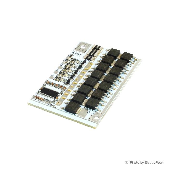
3S/4S/5S 12V 100A BMS 18650 Lithium Battery Protection Board
$2.5000
In stock
SKU
BAT-03-071
Volume discounts:
- +50 4 % $2.4100
- +100 6 % $2.3600
- +300 8 % $2.3100
- +500 10 % $2.2600
- +1000 11 % $2.2200
Ships in 2-3 business days, then:
Free delivery in 12-15 days by Tracked Economic Shipping on orders over $100.
Free delivery in 7-10 days by Express Shipping on orders over $300.
More shipping info

Shop with confidence Learn More
 3S 11.1V 20A BMS 18650 Lithium Battery Protection Board Previous
3S/4S/5S 100A BMS Board Review
The 3S/4S/5S 12V 100A BMS protection board is a multi-cell management module for 3-series, 4-series, or 5-series battery packs using 3.7V nominal lithium-ion cells. At $2.50, it provides core cell-level safety functions: overcharge cutoff, over-discharge cutoff, short-circuit protection, and a 50MA balance circuit. Although designated as a 100A board, its electrical specifications list 60A discharge in same-port mode and 80A discharge in different-port mode alongside the 100A protection limits. Treat the 100A figure as a peak protection threshold, not an unconditional continuous working rating. Builders comparing pack formats can browse battery management system modules to match the board to their pack layout.
Specifications of 3S/4S/5S 12V 100A BMS 18650 Lithium Battery Protection Board
- Single-cell battery overload protect voltage: 3.61-3.69V
- Single-cell battery overload protects voltage recovery: 3.5-3.6V
- Overload protection delay: 1.5-2.5s
- Single-cell battery over-discharge protect voltage: 2.27-2.43V
- Single-cell battery over-discharge protect voltage recover: 2.45-2.65V
- Overload protect Current: 100A
- Over-discharge protection Current: 100A
- Over-discharge protect delay: 0.5-1.5s
- Temperature protection: Yes, it has a Temperature control interface.
- Power off protect: Yes
- Scarcity protection: Yes
- Delay shortage: 100-600 us
- Shortage protects recover mode: Off-load release.
- Current discharge contact: 80A
- Synopline discharge current: 60A
- Charging current: 60A
- Function balance: yes
- Balance Ampere (Current): 50MA
3S/4S/5S BMS Board Compatibility and Wiring
This protection board is intended for 3.7V-class lithium chemistries: lithium manganese oxide (LMO), ternary lithium, and lithium cobalt oxide (LCO). It is not specified for lithium iron phosphate (LiFePO4) cells, which use lower nominal and charge-termination voltages. Connecting LiFePO4 cells risks severe overcharging because the onboard cutoff thresholds are tuned for standard lithium-ion profiles.
Terminal voltage depends on the series count selected during pack assembly. A 3S configuration reaches 12.6V fully charged, a 4S pack reaches 16.8V, and a 5S pack tops out at 21.0V. Configure the board for the intended series count before connecting cells. Verify the exact solder-pad or jumper arrangement against the markings on the physical board before assembly.
Wire balance leads in strict sequence, starting at pack negative (B−), continuing through each intermediate series junction (B1, B2, B3, B4 depending on pack size), and ending at total pack positive (B+). Out-of-order connections can damage the balance circuitry. Pack interconnects also need solid conductor materials, such as battery-pack nickel strip interconnects, to avoid resistive voltage drops between series groups.
The module supports two wiring configurations. In same-port (common-port) mode, charging and discharging share the negative terminal (C−), with support for up to 60A charge and 60A discharge. In different-port (separate-port) mode, charge negative connects to C− and load negative connects to P−, raising the listed discharge figure to 80A while retaining a 60A charge limit. Follow the silk-screened labels on the received PCB to confirm terminal assignments. The board also has a temperature control interface, though a 10 kΩ NTC thermistor is not listed as included and must be sourced separately if thermal protection is required.
| Parameter | Specification / Requirement |
|---|---|
| Supported Chemistries | LMO, ternary lithium, LCO (3.7V nominal); LiFePO4 not supported |
| Series Configurations | 3S, 4S, or 5S (hardware configuration required) |
| Maximum Charge Voltage | 3S: 12.6V | 4S: 16.8V | 5S: 21.0V |
| Charger Type | Dedicated CC/CV lithium-ion charger matching pack voltage |
| Common-Port Current | 60A discharge, 60A charge |
| Separate-Port Current | 80A discharge (P−), 60A charge (C−) |
| Temperature Interface | Present on PCB; external NTC sensor requirement depends on revision |
| Data Interfaces | None (no Bluetooth, UART, CAN, or display outputs) |
Where a configurable series count is unnecessary, a dedicated board removes the configuration step. For three-cell setups, a fixed 3S 20A Li-ion pack protection board offers a simpler wiring path. Four-cell builds can use a fixed 4S 16.8V BMS. Five-cell power-tool assemblies may suit a dedicated 5S drill-tool BMS with built-in thermal cutoff.
3S/4S/5S 100A BMS Current Limits and Safety Notes
Assess the manufacturer’s current figures carefully before using this board in a build. It incorporates 15 high-power MOSFETs, with 8 dedicated to discharge and 7 to charge, but current handling changes significantly with the load wiring. The protection circuitry triggers at 100A for over-discharge and overload conditions. Continuous operation depends on wiring mode: 60A in same-port mode and 80A in different-port mode.
Continuous high-current operation produces substantial heat across the switching FETs and current-sensing shunts. Exact continuous thermal dissipation and derating curves are not supplied. Operating near the upper current limits therefore requires active cooling or supplementary heatsinking. High-amperage connections should use an appropriate terminal, such as a high-current detachable battery connector, so the physical interface does not introduce localized resistance.
The integrated balancing function operates at 50MA using passive bleed balancing. It gently bleeds charge through onboard resistors when individual cells exceed the balancing voltage threshold. A 50mA bleed current is intended to maintain balance across well-matched cells during normal float charging; it cannot compensate for heavily degraded, mismatched, or reclaimed cells with disparate capacities. For faster equalization across multi-cell packs, additional 3S–8S battery balancing hardware can supplement the onboard passive circuit. An external balancer does not replace BMS cutoff protection.
For higher cell counts or factory-integrated thermal management, consider a 6S BMS with integrated cooling heatsink rather than adapting a 5S board to an undersized layout.
Operational Limitations
- Current Ratings: 100A is an overcurrent protection trigger, not an uncooled continuous load rating. Sustained output is limited to 60A or 80A, depending on port selection.
- Thermal Management: Validate board temperature under load. High-current enclosures require adequate airflow or physical heat spreaders.
- Passive Balancing Only: The 50mA bleed current cannot restore severely drifted or degraded cell groups.
- No System Telemetry: No digital bus, configuration software, or state-of-charge output is available.
- Traceability and Certification: The board lacks formal industrial compliance documentation, making it suitable for prototypes and DIY builds rather than certified commercial assemblies.
3S/4S/5S 100A BMS Setup Check
Commission a pack methodically before connecting high-capacity lithium cells to the board. The module operates autonomously, with no firmware setup, drivers, or software configuration required.
- Verify Cell Chemistry: Confirm that all cells are 3.7V nominal lithium-ion types (LMO, LCO, or ternary). Do not use LiFePO4 cells.
- Configure Series Count: Inspect the physical PCB and complete any required solder bridges or jumper links to select 3S, 4S, or 5S operation before wiring the cells.
- Check Group Voltages: Use a digital multimeter to measure every series group individually. Confirm that all parallel groups are balanced within 0.05V of each other before attaching the BMS.
- Connect Balance Leads in Sequence: Solder or plug the negative-most battery terminal to B−. Attach each intermediate balance tap in ascending order (B1, B2, B3, B4), finishing at the positive-most terminal (B+).
- Wire Load and Charge Paths: For common-port setups, connect charger and load negative to C−. For separate-port setups, attach charger negative to C− and load negative to P−. Battery positive connects directly to load and charger positive leads through an external fuse.
- Check Temperature Interface: If thermal cutoff is required, verify whether your board revision requires soldering an external 10 kΩ NTC thermistor across the designated sensor pads.
- Perform Low-Current Validation: Connect an appropriate CC/CV charger (12.6V for 3S, 16.8V for 4S, 21.0V for 5S) at a conservative charge rate. Confirm that the pack accepts current, then test with a mild load while monitoring board and wiring temperatures.
If the board shuts down after an overcurrent or short-circuit event, remove the load entirely. Its protection circuitry uses off-load release recovery, meaning output restores once the fault is cleared and the load circuit is broken.
3S/4S/5S 100A BMS vs Fixed-Count BMS Boards
The choice between a configurable 3S/4S/5S board and a fixed-count protection module depends on pack voltage, continuous current requirements, and the need for dedicated cooling. Configurable boards cover multiple projects. Fixed boards provide simpler PCB layouts and clearly defined ratings.
| Model | Series Count | Operating Current | Protection / Peak Current | Key Features |
|---|---|---|---|---|
| 3S/4S/5S 100A BMS | 3S, 4S, 5S | 60A (same port) / 80A (different port) | 100A | Configurable cell count, dual-port options, 50mA balance |
| 3S 11.1V 20A BMS | 3S | 20A continuous | Not specified | Fixed 3S configuration, balanced charging, compact profile |
| 4S 16.8V 40A BMS | 4S | 40A continuous | 80A overcurrent | Fixed 4S configuration, 60mA balance, self-recovery |
| 5S 18.5V 20A BMS | 5S | 8–20A operating | 30A overcurrent | Fixed 5S configuration, integrated 70°C thermal protection |
| 6S 22.2V 40A BMS | 6S | 40A continuous | 70A peak | Fixed 6S configuration, factory-fitted cooling heatsink |
| 7S 29.4V 15A BMS | 7S | 15A operating | 20A transient | Fixed 7S configuration, low quiescent current (<30µA) |
Modular options are available for larger systems outside the 3S–5S range. Packs requiring higher potential can use a dedicated 7S 29.4V Li-ion pack protection board. For higher series counts with heavy sustained loads, a board with an integrated heatsink offers more heat management than a bare PCB.
3S/4S/5S 100A BMS Accessories and Pack Requirements
A bare BMS board is only one part of a safe battery system. It does not regulate charging voltage, convert output levels, or prevent short circuits caused by physical cell movement. Source the required complementary hardware before assembling a pack.
Required Components
- Matched Lithium-Ion Cells: Cells must have identical capacity and internal resistance, such as vetted 18650 cells for a matched battery pack. Never mix old and new cells or combine different capacities.
- Interconnect Strips: Use low-resistance conductors, such as battery-pack nickel strip interconnects, welded securely across cell terminals.
- CC/CV Charger: Use a dedicated lithium-ion charger calibrated to the exact pack voltage (12.6V for 3S, 16.8V for 4S, or 21.0V for 5S). The BMS is not a charger.
- Series Overcurrent Fuse: Place a fast-acting DC fuse directly at the main positive terminal, sized to protect wiring and cells during an external fault.
- Insulated Heavy-Gauge Lead Wire: Use high-strand silicone wire rated for your target discharge current.
- Digital Multimeter: Essential for verifying cell group voltages and balance lead polarity before soldering.
Recommended Components
- High-Current Plugs: Use polarized connectors, such as a high-current detachable battery connector, to avoid accidental polarity reversals during connection.
- Insulation Materials: Barley paper (fish paper), Kapton tape, and high-diameter PVC heat-shrink tubing protect cells and terminals from abrasion and short circuits.
- Thermal Monitoring Tools: Use an infrared thermometer or contact thermocouple to monitor switching FET temperatures during high-drain test cycles.
Optional Additions
- Auxiliary Balancing Hardware: An external balancer such as the additional 3S–8S battery balancing module can assist when conditioning larger parallel cell assemblies.
- Panel Voltmeter or Shunt Monitor: An external display module can monitor pack voltage and draw in real time, compensating for the board's lack of telemetry.
3S/4S/5S 100A BMS FAQ
Is this really a 12V BMS?
Yes, but only in a 3S configuration. In a 3S setup, standard lithium-ion cells operate around 11.1V nominal and charge to 12.6V, matching 12V-class applications. In 4S mode, the full-charge voltage is 16.8V; in 5S mode, it reaches 21.0V.
Can I use this BMS with LiFePO4 cells?
No. This board is calibrated for 3.7V nominal chemistries (LMO, LCO, and ternary lithium). LiFePO4 cells have lower maximum charge (3.65V) and nominal (3.2V) ratings, so using this board with LiFePO4 chemistry will result in dangerous cell overcharging before the BMS cutoff triggers.
Does this board automatically detect 3S, 4S, or 5S?
No, it does not auto-detect series count. Manually configure the PCB for 3S, 4S, or 5S through the designated solder pads or jumper points before connecting the battery pack.
Does 100A mean 100A continuous discharge?
No. The 100A rating refers to overload and short-circuit protection cutoff thresholds. Functional continuous discharge is rated at 60A in same-port mode and 80A in different-port mode, and both operating points require adequate cooling.
Is the balancing function active balancing?
No, this module uses passive bleed balancing at 50MA. It dissipates excess voltage as heat through small onboard shunt resistors when cells approach full charge rather than actively transferring energy between cells.
Is the temperature sensor included?
No, a thermistor is not stated as included in the package. The board has a temperature control interface, but builders who need thermal protection must provide and solder the appropriate NTC thermistor, typically 10 kΩ, to the interface pads.
Does this include a charger, USB output, or battery monitor?
No. This is strictly a protection and balance PCB. It does not regulate input voltage, provide USB power delivery, or report voltage metrics over Bluetooth, UART, or a display.
What charger voltage do I need for a 4S Li-ion pack?
A 4S pack requires a dedicated lithium-ion CC/CV charger with a 16.8V output (4.2V per cell). By comparison, a 3S pack requires 12.6V, and a 5S pack requires 21.0V.
What happens after a short-circuit or overcurrent shutdown?
The board uses off-load release recovery. After a short-circuit or excessive-current load shuts down the MOSFETs, completely disconnect the load to allow the protection logic to reset.
Can I use this for an e-bike, inverter, or power-tool pack?
It can be used in these builds if peak inrush current and sustained draw remain within the board's operational limits (60A/80A). High-drain inductive loads such as motors must be tested carefully to confirm that start-up surges do not trigger nuisance shutdowns or overheat the board.
What if I need a 6S or 7S Li-ion pack?
This module cannot be expanded beyond 5S. For higher-voltage configurations, choose a dedicated higher-series module such as a 6S BMS with integrated cooling heatsink or a 7S 29.4V Li-ion pack protection board.
Purchase Decision Summary
| Recommendation | Target Profile |
|---|---|
| Ideal for | Experienced builders assembling custom 3S, 4S, or 5S packs using matched 3.7V lithium-ion cells who need low-cost protection and understand physical wiring and thermal management. |
| Maybe for | Moderate-draw robotics, DIY power-tool battery rebuilds, and portable DC power supplies operating well within the 60A/80A sustained limits with external fusing. |
| Avoid if | Building LiFePO4 packs, requiring verified uncooled 100A continuous output, needing software telemetry/Bluetooth, or building certified consumer products. |
Buying Checklist
- Confirm your cells are 3.7V nominal Li-ion (LMO, ternary, LCO), not LiFePO4.
- Determine your series count (3S = 11.1V nom / 12.6V max; 4S = 14.8V nom / 16.8V max; 5S = 18.5V nom / 21.0V max).
- Select an external CC/CV charger matched precisely to your pack's fully charged voltage.
- Plan your wiring mode: same-port (60A discharge / 60A charge) or separate-port (80A discharge / 60A charge).
- Ensure you have a DC fuse and suitable wire gauge rated for your operational current.
- Verify that your cells are closely matched in capacity and health; the 50mA balance circuit cannot fix severely imbalanced cells.
- Source a 10 kΩ NTC sensor if your build requires active thermal cutoff.
- Measure physical clearances in your pack enclosure once the board arrives, as exact PCB dimensions can vary slightly between production batches.
| Cell Count | 3S, 4S, 5S |
|---|---|
| Nominal Voltage (V) | 12V |
| Max Current (A) | 100A |
| Cell Balancing | Balanced charging |
| Protection | overcharging,over-discharging,short circuits,overcurrent,disconnection protection,overcharge protection,with balance |
| Application | power bank,electric vehicle battery system,solar power storage unit |
Write Your Own Review

Please complete your information below to login.
Sign In
Create New Account