
Product added to cart

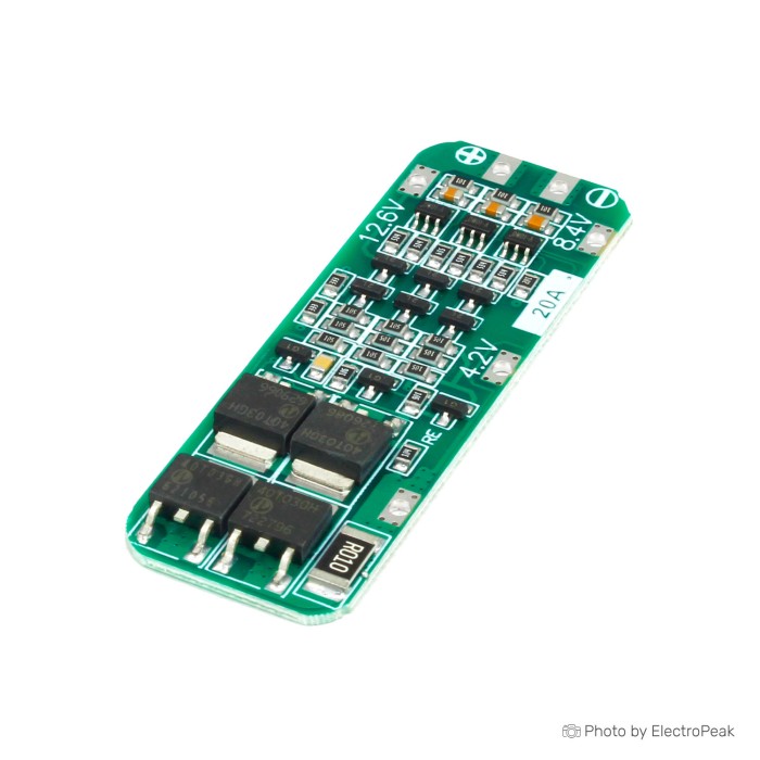
3S 11.1V 20A BMS 18650 Lithium Battery Protection Board
$0.3900
In stock
SKU
BAT-03-067
Volume discounts:
- +100 3 % $0.3800
- +500 5 % $0.3700
- +1000 8 % $0.3600
- +10000 10 % $0.3500
Ships in 2-3 business days, then:
Free delivery in 12-15 days by Tracked Economic Shipping on orders over $100.
Free delivery in 7-10 days by Express Shipping on orders over $300.
More shipping info

Shop with confidence Learn More
 Lithium Polymer Battery Balancer Module Previous
3S 11.1V 20A BMS Review: Is It Right for Your 3S Battery Pack?
This 3S 11.1V 20A BMS is a lithium-ion 18650 battery protection board for 3-series DIY battery packs. It combines overcharge, over-discharge, overcurrent, and short-circuit protection with balanced charging support and low standby current, and lists a maximum continuous discharge current of 20A. It suits intermediate builders who can verify pack configuration, provide an external charger, confirm wiring order, and assess real load currents against thermal constraints.
For safety-critical, commercial, or sustained high-current applications requiring certified thermal test curves, traceable revisions, and fully documented balance currents, use a documented platform from standard battery management system modules.
Specifications of 3S 11.1V 20A BMS 18650 Lithium Battery Protection Board
- Model Name/Number: Li-ion 18650 Lithium Battery Protection Board 3S Battery Management System
- Usage/Application: Battery management & protection
- Size: rectangle
- Weight: 100g
- Battery Type: Lithium-Ion
- Max Continuous Discharge Current: 20A
- Input Voltage: 11.1V
- Battery Configuration: 3 series
- Protection: Short circuit protection
- Protection: Overcharge protection
- Protection: Over-discharge protection
- Protection: Overcurrent protection
- Material: silicone
3S 20A Protection Board Specifications Explained
These raw specifications translate into practical electrical and physical constraints. Check that this 3S 20A protection board fits both before building your pack.
| Specification | Listed Value | Why It Matters |
|---|---|---|
| Battery Configuration | 3 series | Designed specifically for three lithium-ion cells wired in series. It cannot be used for 1S, 2S, or 4S builds, as the onboard sense circuitry depends on three individual cell taps to monitor voltages correctly. |
| Input Voltage | 11.1V | Represents the nominal operating voltage of three series-connected 3.7V lithium-ion cells (3 × 3.7V = 11.1V). It indicates pack voltage rather than charger voltage. |
| Max Continuous Discharge Current | 20A | Sets the upper boundary for continuous current delivery through the onboard switching MOSFETs under favorable thermal conditions. |
| Protection Functions | Overcharge, over-discharge, overcurrent, short circuit | Provides essential autonomous cutoff protection against cell damage, thermal runaway, and pack degradation during operating faults. |
| Cell Balancing | Balanced charging function included | Bleeds current from higher-voltage cells during charging to help maintain cell voltage symmetry across the pack over repeated charge cycles. No specific balance current value is listed. |
| Standby Power | Low standby current | Draws minimal current while idle to reduce the risk of deeply draining an unused pack over extended storage periods. No numerical idle microamp rating is provided. |
| Physical Envelope | Size: rectangle; Weight: 100g; Material: silicone | Indicates general form factor and packaged shipping mass. Detailed millimetre dimensions and exact bare-board materials are not specified, requiring pre-installation fit checks. |
Choose battery management system modules by weighing these electrical thresholds against your expected continuous operating loads.
3S 20A Protection Board Limits and Safety Considerations
The listed 20A maximum continuous discharge rating is an upper ceiling, not a guaranteed continuous load capacity under every mounting condition. Component variance exists across generic board revisions, and continuous operation near 20A can generate substantial heat in the switching MOSFETs. For sustained loads above 10A to 15A, adequate airflow, external heat sinking, or thermal validation is strongly recommended.
This module lacks exact-SKU thermal curves, confirmed overcharge/over-discharge trip voltage thresholds, specific continuous charge-current ratings, and manufacturer revision tracking. Balanced charging support is included, but the precise balance circuit type and balancing current are not documented. Severely mismatched cells will not be rapidly equalized during a single charge cycle.
The 100g weight likely reflects packaged shipping weight rather than bare PCB mass, and the listed "silicone" material specification should not be read as conformal silicone potting or a flexible substrate. For sustained high-current packs, the 3S/4S/5S 12V 100A High-Current BMS lists a 60A–80A continuous discharge rating and includes a dedicated temperature-control interface.
3S 11.1V 20A BMS Compatibility and Wiring
This 11.1V battery protection board works exclusively with 3-series standard lithium-ion chemistries, rated at a nominal 3.6V–3.7V per cell. It is not compatible with LiFePO4 cells, which use lower nominal (3.2V) and charge cut-off (3.65V) voltages. For a two-cell pack, use a dedicated 2S battery-pack protection board. Four-cell systems need a 4S lithium battery protection board instead.
| Parameter | Compatibility Status | Technical Details |
|---|---|---|
| Battery Chemistry | Standard Lithium-Ion only | Intended for 3.6V/3.7V nominal cells. Incompatible with LiFePO4 due to mismatched protection trip points. |
| Pack Configuration | 3S (3 series cells) | Requires connection to four cell taps (0V, 3.7V, 7.4V, 11.1V nominal). |
| External Charger | 12.6V CC/CV Li-ion charger | Pack full-charge voltage is 12.6V (3 × 4.2V). The board does not regulate voltage down from generic DC power supplies. |
| Software / Drivers | None required | Purely hardware-based protection circuit; no microcontroller, firmware, or libraries required. |
Durable interconnections between cell terminals are critical when assembling a pack. Dedicated battery-pack interconnection strip helps maintain low resistance across the series junctions.
Inspect the board's silkscreen markings before soldering. Standard 3S wiring convention calls for connecting the battery balance leads in this strict sequence:
- Connect B− to the negative terminal of the first cell (0V pack reference).
- Connect B1 to the junction between cell 1 positive and cell 2 negative (3.7V nominal).
- Connect B2 to the junction between cell 2 positive and cell 3 negative (7.4V nominal).
- Connect B+ to the positive terminal of the third cell (11.1V nominal / 12.6V fully charged).
- Attach charge and load wiring to P+ and P− (or shared B+/P− terminals, as indicated by the board's silkscreen).
Generic 3S protection boards can show a zero-volt reading across P+ and P− immediately after wiring. In most cases, the protection IC remains locked until a 12.6V CC/CV charger is momentarily connected to the output pads.
3S 11.1V 20A BMS Accessories for a Complete Battery Pack
A bare protection board cannot function on its own. A functional, secure 3S battery pack also needs complementary components.
Required Components
- Matched Lithium-Ion Cells: Use three cells matched in internal resistance, state of charge, and capacity. Suitable options include 18650 cells for a 3S pack.
- External 12.6V CC/CV Charger: Required to charge the pack safely and activate the BMS output on first connection (charger not supplied).
- Interconnection Hardware: Use low-resistance pure nickel or nickel-plated steel, such as battery-pack interconnection strip, spot-welded across cell terminals.
- Power & Sense Wiring: Use copper wire rated for your target continuous current load (wiring not supplied).
Recommended Accessories
- Cell Spacers: Rigid mounting frames such as a three-cell 18650 holder bracket prevent cell rubbing and short circuits under vibration.
- Output Connector: Use a keyed, high-current connection such as a battery-pack output connector for reliable pack disconnects.
- Multimeter: Required to verify individual cell voltages and sequence steps before attaching the board (multimeter not supplied).
- Insulation Materials: Use barley paper and Kapton tape to isolate the board from cell casings (insulation not supplied).
Optional Additions
- Dedicated In-Line Fuse: Provides secondary protection on the primary discharge lead for redundant short-circuit security (fuse not supplied).
- Spot Welder: A battery-tab welder supports secure pack assembly without exposing cell caps to excessive iron heat (welder not supplied).
3S 11.1V 20A BMS Alternatives for Different Pack Voltage and Current
Use different protection hardware when your pack voltage requirements or expected discharge currents fall outside this 3S 20A board's limits. Cell count and current requirements both matter.
| Model | Configuration | Continuous Current | Primary Use Case |
|---|---|---|---|
| 3S 11.1V 20A BMS (This Board) | 3S (11.1V nominal) | 20A listed max | Low-to-moderate-current 3S Li-ion packs, DIY projects, portable devices. |
| 2S 7.4V 5A BMS (HX-2S-02) | 2S (7.4V nominal) | 3A working / 5A peak | Ultra-compact two-cell battery packs with low current draw. |
| 4S 14.8V 12A BMS (HX-4S-A01) | 4S (14.8V nominal) | 6–8A working / 12A peak | Four-cell battery configurations requiring 14.8V nominal output. |
| 3S/4S/5S 12V 100A High-Current BMS | 3S, 4S, or 5S configurable | 60A–80A continuous | High-current motor drives, inverters, and high-load power packs. |
Where dedicated cell equalization is needed alongside a primary protection board, a standalone battery balancer can provide 100mA balancing current across 3S–8S packs. Standalone balancers do not provide overcharge, over-discharge, or short-circuit cutoff and cannot replace a BMS.
3S 11.1V 20A BMS FAQ and Buying Checklist
Is this a 12V BMS or an 11.1V BMS?
This board is for an 11.1V nominal pack made from three series-connected 3.7V lithium-ion cells. It is often referred to colloquially in 12V-class projects, but a fully charged three-cell pack reaches 12.6V and requires a dedicated 12.6V CC/CV charger rather than a fixed 12V power supply.
Does this board charge 18650 cells by itself?
No. This board is a protective management supervisor; it does not regulate charging current or step up voltages. Connect an external 12.6V CC/CV lithium-ion charger to the charge input terminals.
Is 20A safe as a continuous load?
The board lists a 20A maximum continuous discharge current, but continuous operation at that threshold without active cooling or airflow can cause significant MOSFET heating. Conservative enclosed-pack designs de-rate continuous draw or use a higher-current battery management board.
Does this 3S 20A protection board balance the cells?
Yes, the board includes balanced charging functionality. The specific balancing current and threshold window are not published, so pre-balance and match cells before pack assembly.
Why is there no output from my 3S BMS after wiring it?
Generic 3S protection boards frequently enter a protective sleep mode after initial wiring. Momentarily connecting a 12.6V CC/CV charger across the P+ and P− terminals typically resets the protection circuit and restores normal terminal voltage.
Can this board be used with LiFePO4 cells?
No. This board is designed strictly for 3.6V/3.7V nominal lithium-ion chemistries. LiFePO4 cells operate at lower voltage thresholds (3.2V nominal, 3.65V peak) and will be overcharged if connected to standard lithium-ion management boards.
What order should the 3S BMS cell connections use?
Connect ground first: start with B−, then connect B1, B2, and B+ in sequence. Confirm pad designations on the PCB silkscreen before soldering to avoid damaging the sense circuitry.
Are the dimensions suitable for my battery enclosure?
The board is listed with a rectangular footprint and a 100g weight, but exact millimetre dimensions are not provided. Verify clearances inside your custom enclosure before completing permanent mounting.
Purchase Decision Summary
- Ideal for: Intermediate hobbyists and makers assembling or repairing 11.1V nominal 3S 18650 packs with low-to-moderate continuous current demands below 15A.
- Maybe for: Replacement use in existing low-current consumer packs where the physical footprint can be verified manually before installation.
- Avoid if: Building packs for sustained high-current power tools, LiFePO4 battery banks, or commercial products requiring traceable components and certified thermal documentation.
Buying Checklist
- [ ] Pack uses three series-connected lithium-ion cells (not LiFePO4, 2S, or 4S).
- [ ] A dedicated 12.6V CC/CV lithium-ion charger is available.
- [ ] Continuous current draw remains comfortably within thermal margins below 20A.
- [ ] All three cells are pre-tested and closely matched in voltage and capacity.
- [ ] Tools and equipment are ready to follow the B−, B1, B2, B+ sequential wiring order.
- [ ] Enclosure allows adequate physical clearance and heat dissipation around the PCB.
| Cell Count | 3S |
|---|---|
| Nominal Voltage (V) | 11.1V |
| Max Current (A) | 20A |
| Cell Balancing | Balanced charging |
| Protection | Overcharge protection,Over-discharge protection,Overcurrent protection,Short circuit protection |
| Board Dimensions (mm) | rectangle |
| Application | Battery management & protection |
Write Your Own Review

Please complete your information below to login.
Sign In
Create New Account