
Product added to cart

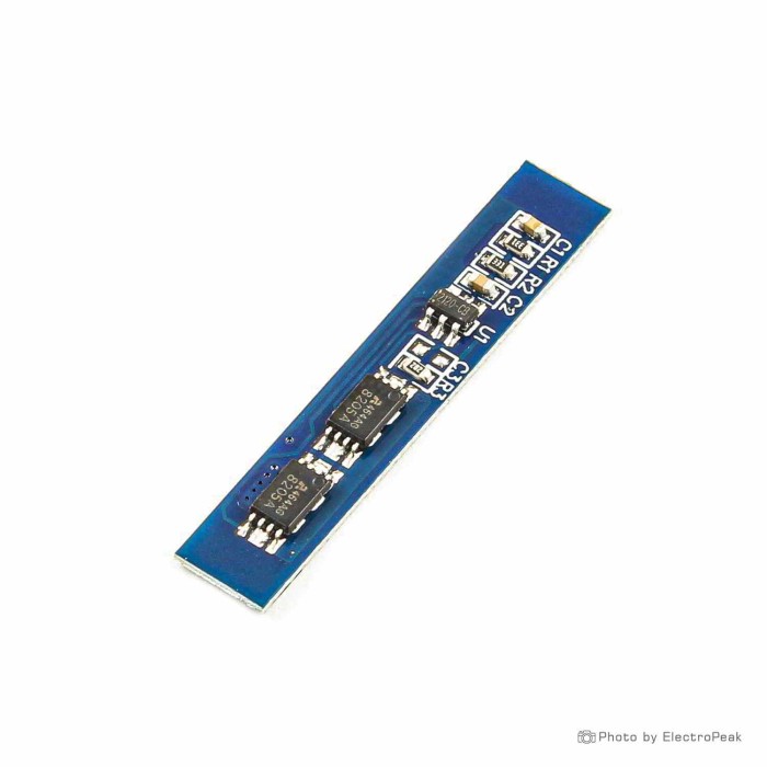
2S Lithium Battery Charging Protection Board - 7.4V, 5A
SAVE $0.0500
$0.2400 $0.2900
In stock
SKU
BAT-03-040
Ships in 2-3 business days, then:
Free delivery in 12-15 days by Tracked Economic Shipping on orders over $100.
Free delivery in 7-10 days by Express Shipping on orders over $300.
More shipping info

Shop with confidence Learn More
 3S Lithium Battery Charging Protection Board - 11.1V, 10A Previous
HX-2S-02 2S Lithium Battery Protection Board Review
The HX-2S-02 is a compact 2S lithium-ion battery protection board for two-cell battery assemblies with a 7.4V nominal voltage. It monitors connected cells and provides overcharge, over-discharge, overcurrent, and short-circuit cutoff. Its slim profile suits space-constrained DIY pack builds, but this board is intended for low-current applications; projects requiring integrated battery charging, verified 5A continuous discharge, documented cell balancing, or formal compliance certifications need a broader battery management solution from our battery management system modules selection.
Specifications of 2S Lithium Battery Charging Protection Board - 7.4V, 5A
- Model: HX-2S-02
- Overcharge protection voltage: 4.25-4.35V±0.05V
- Over-discharge protection voltage: 2.3-3.0V±0.05V
- Maximum operating current: 3A
- Operating temperature: -40°C to 50°C
- Maximum instantaneous current: 5A
- Storage temperature: -40°C to 80°C
- Quiescent current: Less than 3uA
- Effective life: More than 50000 hours
- Resistance: Less than 45mΩ
- Short-circuit protection: Can protect, recovery requires charging
- Dimensions: 38x8x2.5 mm
HX-2S-02 Specifications Explained: Current, Voltage, and Size
A reliable battery pack starts with matching the protection board to its electrical and physical constraints. In battery terminology, 2S means two lithium-based cells wired in series, producing a 7.4V nominal pack voltage. A conventional 2S lithium-ion or lithium-polymer assembly reaches 8.4V when fully charged, or 4.2V per cell, which is distinct from its nominal rating.
| Specification | Listed Value | Why It Matters for Your Build |
|---|---|---|
| Overcharge Protection Voltage | 4.25-4.35V±0.05V | Cuts charging current if either individual cell exceeds this window, preventing cell swelling and thermal stress. |
| Over-discharge Protection Voltage | 2.3-3.0V±0.05V | Disconnects the load when cell potential drops into this cutoff threshold, preventing permanent capacity loss. |
| Maximum Operating Current | 3A | The primary engineering figure for sustained discharge. Continuous circuit loads should remain within 3A. |
| Maximum Instantaneous Current | 5A | Handles transient startup spikes. Permissible duration and duty cycles are not specified, so do not design for sustained 5A draw. |
| Board Dimensions | 38x8x2.5 mm | The slim footprint fits along the side of dual cylindrical cells or small flat packs where PCB space is limited. |
| Quiescent Current | Less than 3uA | Parasitic drain on idle cells is minimal, reducing self-discharge rates during long periods of storage. |
| Internal Resistance | Less than 45mΩ | Minimizes voltage drop across the protection switching elements under operational loads. |
| Operating Temperature | -40°C to 50°C | The rated ambient window for board operation; lithium cell chemistry will dictate narrower practical pack limits. |
| Effective Life | More than 50000 hours | Expected component operational life under listed conditions, though real-world pack life depends on cell cycling and thermal care. |
The 38x8x2.5 mm form factor makes integration easier inside compact handheld housings. That small circuit board also has limited copper mass for heat dissipation. For projects drawing sustained currents beyond 3A, our 2S board for higher continuous current lists a 10A continuous discharge working current and a 20A instantaneous limit.
HX-2S-02 2S BMS Wiring, Compatibility, and First Test
This module is strictly compatible with two-cell lithium-ion or lithium-polymer packs. It cannot be used with single-cell systems, three-cell packs, or lithium iron phosphate (LiFePO₄) chemistry because their voltage detection bands do not match. Use a dedicated single-cell lithium protection board for single-cell designs. Three-cell builds require an appropriate 3S 11.1V battery protection board.
Five solder-pad connections are required on the PCB:
- B−: Connects to the overall pack negative terminal, the negative pole of Cell 1.
- BM / MB: Connects to the midpoint node between Cell 1 and Cell 2, at the junction of Cell 1 positive and Cell 2 negative.
- B+: Connects to the overall pack positive terminal, the positive pole of Cell 2.
- P+ / P−: Shared terminals for both the discharge output to your load and the charging input from an external power source.
Follow this safe bench assembly sequence:
- Inspect two healthy, matched cells and use a digital multimeter to verify that their resting voltages are within 0.05V of each other.
- Confirm the physical silkscreen labeling on your board, since terminal positions can vary across production revisions.
- Wire the battery cells in series order, starting from B−, then BM, then B+.
- When using an enclosure such as a two-cell 18650 battery holder, make sure its internal contacts support tapping the required midpoint wire.
- Verify overall pack voltage across B+ and B− before attaching anything to P+ and P−.
- If no voltage appears on first assembly, apply an external 8.4V regulated power source across P+ and P− to initialize the switching logic.
- Keep initial bench load testing within the 3A maximum operating current while monitoring board temperature.
HX-2S-02 Limitations: Charging, Balancing, and Protection Reset
A protection board is not a battery charger. The HX-2S-02 monitors cell voltage and disconnects the circuit during abnormal faults, but it contains no buck-boost conversion or constant-current/constant-voltage (CC/CV) control circuitry. Supplying unmanaged DC power directly to P+ and P− can damage your cells. Charging requires a dedicated 8.4V CC/CV lithium charger.
Cell balancing is not confirmed for this board model. If the two cells drift in capacity or state of charge over time, the board will trip when whichever individual cell crosses a fault limit first. If your design requires cell equalization, consider an alternative format such as the round 2S board with listed balanced charging. External balancers such as a standalone multi-cell battery balancer support packs starting at 3S, so 2S balancing must be handled by an onboard circuit or dedicated bench equipment.
Short-circuit recovery is listed as requiring an external charge voltage. After an output short or severe over-discharge event, the internal MOSFET switches turn off. Removing the fault alone may not restore voltage across P+ and P−; connecting a proper 8.4V charger is typically required to clear the fault latch. The board also lacks integrated temperature sensors, state-of-charge fuel gauging, data communication buses, and formal certification records. It is not suitable for high-drain motors, power tools, electric mobility, or unattended life-critical systems.
2S 18650 Protection Board Accessories and Pack-Build Requirements
A reliable battery pack requires appropriate interconnects, hardware, and safety components alongside the protection PCB.
Required Hardware
- Matched Lithium Cells: Two series-connected 18650 or lithium-polymer cells with identical capacity, age, and internal resistance.
- External 8.4V CC/CV Charger: A regulated charging source that provides appropriate constant-current and constant-voltage stages.
- Interconnect Material: Low-resistance conductors, such as a battery interconnect strip, to join cell terminals to board pads.
- Digital Multimeter: An essential test instrument for verifying individual cell voltages and polarity before soldering.
Recommended Hardware
- Cell Holder: A two-cell 18650 battery holder simplifies physical pack mounting, provided midpoint access is wired.
- Replacement Cells: Fresh 18650 cells, such as 18650 cells for a 2S pack, for basic prototyping assemblies.
- Inline DC Fuse: Install on the main output lead as secondary overcurrent protection.
- Thermal Probe / Infrared Thermometer: Useful for checking component temperatures during peak-load testing.
- Insulation Materials: Kapton tape and heat shrink tubing prevent accidental contact across exposed nickel and PCB traces.
Optional Additions
- Main Connector: A keyed, polar connector such as a detachable battery-pack connector helps prevent accidental reverse polarity when connecting loads.
- DC-DC Step-Down Regulator: Regulates the 6.0V–8.4V pack output down to a stable 5V or 3.3V rail for microcontrollers and sensors.
- External Battery Fuel Gauge: Provides a visual state-of-charge indicator because this module lacks telemetry outputs.
2S 7.4V Protection Board Alternatives: 1S, 3S, and Higher-Current Options
Different pack configurations and current profiles require different board selections. Match the options below to your pack architecture and load parameters.
| Module | Cell Count | Operating / Continuous Current | Instantaneous Limit | Dimensions | Notable Attributes |
|---|---|---|---|---|---|
| HX-2S-02 (This Board) | 2S (7.4V) | 3A | 5A | 38x8x2.5 mm | Ultra-narrow profile for compact low-power builds. |
| 1S 3.7V 2A Protection Board | 1S (3.7V) | 2A | 2.5A | 30x3.7x2.2 mm | Micro-footprint single-cell protection for wearables and small modules. |
| slim 2S 18650 BMS with listed 0–5A working current | 2S (7.4V) | 0–5A | 6–7A | 38x8x2.6 mm | Slim form factor with a listed 50W dissipation rating. |
| 2S 7.4V 10A Protection Board | 2S (7.4V) | 10A | 20A | 46.7x23.3x3.15 mm | Higher current handling for medium-drain portable equipment. |
| high-current 2S balanced BMS | 2S (7.4V) | 20A | Not specified | Rectangular PCB | Handles loads up to 168W; includes listed balancing (cooling derating required). |
| 2S Round 7.4V 5A Protection Board | 2S (7.4V) | 5A | Not specified | Circular PCB | Circular profile for cylindrical battery housings; lists 60mA balance current. |
| 3S 11.1V 10A Protection Board | 3S (11.1V) | 10A | Not specified | Rectangular PCB | Three-cell series protection with 60mA balanced charging support. |
HX-2S-02 2S BMS FAQ and Buying Checklist
Frequently Asked Questions
Is the HX-2S-02 a charger or a protection board?
It is strictly a protection board. It protects cells from over-voltage, under-voltage, overcurrent, and short circuits, but a separate regulated 8.4V CC/CV power source is required to manage battery charging.
Can I use this 2S BMS with one 18650 cell?
No. The circuit expects two series cells and requires the midpoint BM connection to operate. Single-cell builds require a dedicated 1S protection board.
Can I use the HX-2S-02 with three cells in series?
No. Three series cells produce an 11.1V nominal pack, which exceeds this board's voltage limits. A three-cell pack requires a dedicated 3S protection board, or a 4S battery-pack protection board when stepping up to a four-cell 14.8V system.
Can I use this board with LiFePO₄ cells?
No. LiFePO₄ chemistry operates at 3.2V nominal and reaches full charge around 3.65V. This module's overcharge detection range of 4.25–4.35V will dangerously overcharge LiFePO₄ cells.
Is the maximum current 3A or 5A?
The maximum continuous operating current is 3A. The 5A figure is an instantaneous limit for brief spikes; do not design continuous loads around the 5A rating.
Does the HX-2S-02 balance the two cells?
Cell balancing is not confirmed for this board model. Pre-match your cells before pack assembly and check cell voltages manually at intervals.
Why is there no output at P+ and P− after I wire the pack?
Protection boards in this family often wake in a safe, disconnected state. Connect an 8.4V charging voltage across P+ and P− for several seconds to release the protection latch and enable output.
Where does the BM or MB wire connect on a 2S battery pack?
The BM (or MB) wire connects directly to the junction between Cell 1 positive and Cell 2 negative, allowing the IC to measure each individual cell's potential.
Can I use this 2S protection board for a motor or power tool?
Generally no. Electric motors produce substantial inrush and inductive feedback spikes that will trip the 3A operating or 5A instantaneous cutoffs. Use a high-current BMS for motorized equipment.
Does this board show battery percentage or provide temperature protection?
No. It has no communication buses, state-of-charge display drivers, or onboard temperature sensor cutoffs.
Can I charge the battery and power a load simultaneously through P+ and P−?
Simultaneous charge and load pass-through is not documented for this board. Because P+ and P− share one common connection, current flow is determined by the voltage difference between your external source, the cells, and the load.
Purchase Decision Summary
- Ideal for: Compact 2S lithium-ion or lithium-polymer packs powering low-drain microcontrollers, portable instrumentation, and small DIY electronics drawing under 3A continuous.
- Maybe for: Replacing damaged narrow protection modules in low-power consumer devices after verifying pad pinouts, cell voltages, and physical dimensions.
- Avoid if: You need an integrated USB/DC charger, single-cell or three-cell operation, LiFePO₄ chemistry support, active or passive balancing, thermal monitoring, or continuous load currents exceeding 3A.
Buying Checklist
- [ ] My battery pack consists of exactly two series-connected lithium-ion or lithium-polymer cells (7.4V nominal).
- [ ] I have an external 8.4V CC/CV charging source ready for pack charging and board activation.
- [ ] My steady-state load current does not exceed the 3A maximum operating current limit.
- [ ] My project does not require cell balancing, onboard thermal sensors, or battery fuel-gauge outputs.
- [ ] I have verified the physical dimensions (38x8x2.5 mm) will fit inside my project housing.
- [ ] I have a digital multimeter and proper interconnect materials, including a reliable detachable battery-pack connector, to complete the assembly safely.
| Cell Count | 2 |
|---|---|
| Nominal Voltage (V) | 7.4V |
| Max Current (A) | 3A |
| Protection | Overcharge protection,Over-discharge protection,Overcurrent protection,Short-circuit protection |
| Board Dimensions (mm) | 38x8x2.5 |
| Application | Portable devices,Renewable energy systems |
| Operating Temp (°C) | -40 to 50 |
| Internal Resistance | Less than 45mΩ |
| Quiescent Current | Less than 3uA |
| Effective Life | More than 50,000 hours |
| Charging Voltage (Pack) | 8.4V |
Write Your Own Review

Please complete your information below to login.
Sign In
Create New Account