
Product added to cart

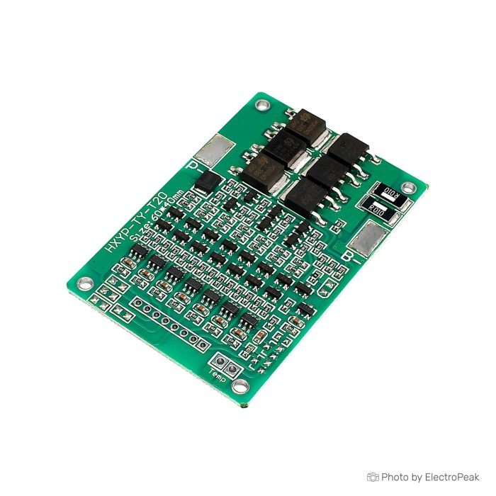
7S 29.4V 15A BMS 18650 Lithium Battery Protection Board
$2.7500
In stock
SKU
BAT-03-072
Volume discounts:
- +25 4 % $2.6400
- +100 6 % $2.5800
- +300 8 % $2.5300
- +500 10 % $2.4700
- +1000 12 % $2.4100
Ships in 2-3 business days, then:
Free delivery in 12-15 days by Tracked Economic Shipping on orders over $100.
Free delivery in 7-10 days by Express Shipping on orders over $300.
More shipping info

Shop with confidence Learn More
 2S Lithium Battery Charging Protection Board - 7.4V, 5A Previous
7S BMS 29.4V 18650 Overview
This 7S 29.4V 15A BMS 18650 Lithium Battery Protection Board is for intermediate DIY builders assembling 7-cell lithium battery packs that need overcharge, over-discharge, short-circuit, and balancing functions. It supports an upper operating current of 15A and transient peaks up to 20A across seven series-connected lithium cells charged to 29.4V.
The compact board suits custom packs, but final assembly requires careful verification. The exact terminal layout (common-port versus separate-port), dedicated charge-current rating, balance-current threshold, and temperature monitoring are not documented. Within these parameters, it provides standard protection for custom energy storage, portable electronics, and small DC equipment. Browse additional configurations in our battery management system modules selection.
Specifications of 7S 29.4V 15A BMS 18650 Lithium Battery Protection Board
- Size: 60*40*3.6 mm
- Upper Opearting Current: 15A
- Upper transient Current: 20A
- Overcharge Range: 4.25±0.05V
- Onder Voltage Range: 2.5V±0.05V
- The static current: Less than 30uA
- Charging Voltage: 29.4 V
- Short Circuit Protection: Protected
29.4V Battery Protection Board Specifications Explained
Selecting the right protection board means matching your electrical operating window to the module's safety thresholds. Each listed parameter affects your 7S battery pack assembly.
| Specification | Listed Value | Why It Matters to Your Build |
|---|---|---|
| Charging Voltage | 29.4 V | Seven standard 3.7V nominal lithium cells reach full charge at 4.2V per group (7 × 4.2V = 29.4V). While termed a "24V" pack nominally, the system requires a regulated 29.4V CC/CV charger to reach capacity safely. |
| Upper Operating Current | 15A | Defines the continuous operating ceiling for the pack. Sustained loads should remain comfortably below 15A to prevent thermal stress and premature cut-offs. |
| Upper Transient Current | 20A | Accommodates brief inrush currents from motor starts or capacitive loads without tripping over-current protection. It is not rated for continuous draw. |
| Overcharge Range | 4.25±0.05V | The upper threshold monitored per individual cell group. If any single group exceeds this limit during charging, the BMS cuts off the input to prevent thermal runaway. |
| Onder Voltage Range | 2.5V±0.05V | The lower discharge cut-off per cell group. It stops the load before cells drain into irreversible chemical degradation, though pack designers should note that cell-level discharge curves often end higher. |
| Static Current | Less than 30uA | Quiescent standby drain drawn by the BMS circuitry itself. A draw under 30µA minimizes parasitic self-discharge when storing an assembled pack for extended periods. |
| Short Circuit Protection | Protected | The board disconnects output if a short circuit is detected across the terminals, guarding cells and wiring from catastrophic discharge. Specific reset methods are not documented. |
| Dimensions | 60*40*3.6 mm | The footprint defines enclosure requirements. Always confirm clearance around solder pads, heat-generating traces, and balance wiring before designing a rigid enclosure. |
7S BMS 29.4V Wiring and First-Power Check
This module uses analog threshold monitoring, so no software, firmware, or driver installation is required. Assembly errors can permanently damage the circuitry or create safety hazards. Follow these steps during initial assembly:
- Match and Pre-balance: Measure all cell groups before connecting. Cells in a 7S configuration must be matched in capacity, internal resistance, and voltage before wiring.
- Inspect PCB Markings: Because common-port versus separate-port wiring is not defined in the specification sheet, inspect the silkscreen labels directly on the board to confirm terminal functions (such as B-, P-, and C- if present).
- Connect Main Negative: Securely solder the pack's main negative lead to the designated B- terminal.
- Wire the Balance Leads: Connect the individual balance wires in strict order from the most negative cell junction to the most positive (typically B0 through B7). Never reverse the order of balance leads.
- Verify with a Multimeter: Before plugging the balance harness into the board, verify each intermediate pin voltage with a multimeter. Ensure voltages step up sequentially across all seven series groups.
- First Output Verification: Once the board is connected, measure between the main positive and negative output terminals. The output should read full pack voltage. If zero volts are present, briefly apply a 29.4V CC/CV charger to release the protection state.
Terminate the output connections with a secure battery-pack output connector, such as an XT60 pair, to prevent accidental short circuits during field use.
7S 15A Protection Board Limits and Wiring Checks
When engineering a custom battery pack, what a module does not document matters as much as its rated specifications. Keep these technical limitations in mind:
- Operating Current Headroom: The board states an upper operating current of 15A and an upper transient current of 20A. Because continuous discharge and charge ratings are not split in the documentation, charger selection must remain conservative until port configurations are verified.
- Balancing Specifications: Balanced charging is integrated to equalize series cells near full charge, but the exact balancing current and start voltage are not specified. It functions as a maintenance balancer; heavily mismatched cells will require manual equalization.
- Thermal Monitoring: No documented NTC temperature sensor input or thermal cut-off circuit is provided on this board. If your pack operates inside a sealed enclosure or under heavy continuous load, external thermal monitoring is recommended.
- Cut-off Threshold vs. Cell Chemistry: The under-voltage limit of 2.5V±0.05V protects standard lithium cells from complete collapse. However, your specific cell manufacturer may specify a higher cut-off (e.g., 2.75V or 3.0V) to prolong cycle life.
- Enclosure Tolerances: The board measures 60*40*3.6 mm, but solder joints, thick wiring, and heat shrink will increase overall pack thickness. Verify physical clearances inside your enclosure before final mounting.
For series cell groups, use dedicated battery-cell interconnect material, such as high-current nickel strip, rather than standard copper wire to ensure low-resistance joints. For applications that specifically require higher, documented cell-balancing currents alongside protection circuitry, a dedicated battery balancer module provides up to 100mA balancing across 3S to 8S packs, though it does not replace the protection functions of a BMS.
7S 15A BMS Uses for 18650 Battery Packs
This protection board fits custom 7-cell lithium-ion assemblies where continuous current remains strictly under 15A. Realistic deployments include:
- Portable 24V-Class Power: Field battery packs for DC-powered communications gear, portable test equipment, and off-grid lighting rigs.
- Low-Power Mobility: Small electric scooters, micro-utility carts, or personal mobility setups where motor draw stays under 15A continuous and 20A peak.
- Small Solar and Energy Storage: Buffer storage packs for low-draw solar lighting or compact backup systems utilizing matched 18650 lithium cells for battery-pack assembly.
- Pack Refurbishment: Replacing failed or obsolete protection modules in existing 7S lithium packs, provided dimensions and terminal functions align.
Verify system current draw under full load. A 7S board cannot be adapted for 6S or 8S architectures, as missing or extra series nodes prevent the monitoring logic from operating correctly.
7S BMS vs 6S Protection Boards and Dedicated Balancers
Protection hardware must match your pack's series count, continuous discharge requirements, and balancing needs. Protection boards cannot be mixed across different series configurations.
| Model | Series Count | Max Operating / Discharge Current | Balancing Function | Primary Role |
|---|---|---|---|---|
| 7S 29.4V 15A BMS (This Board) | 7S (29.4V full) | 15A (20A transient) | Integrated (unspecified current) | General protection for 7-cell lithium builds under 15A. |
| 6S 25.2V 14A Protection Board | 6S (25.2V full) | 14A (22A transient) | None | Basic protection for 6-series packs without integrated balancing. |
| 6S board with stated balancing current | 6S (25.2V full) | 12A–14A (20A transient) | 156mA balance current | 6-cell packs requiring defined, higher-current balancing. |
| 6S high-current BMS board | 6S (22.2V nom / 25.2V full) | 40A continuous (70A transient) | Integrated | High-draw 6S configurations requiring heat-sinked cooling. |
| 3S/4S/5S high-current BMS options | 3S, 4S, or 5S configurable | 60A–80A continuous (100A overload) | 50mA balance current | High-power lower-voltage packs needing thermal monitoring. |
| 3~8 Cell LiPo Balancer Module | 3S to 8S adaptable | N/A (balancer only) | 100mA balancing current | Supplementary balancing; provides no protection cut-offs. |
7S BMS 29.4V FAQ
Is this a 24V BMS or a 29.4V BMS?
It is designed for a 7-cell lithium pack that charges to 29.4V. Builders often call a 7S lithium pack "24V" based on nominal cell voltage (7 × 3.7V = 25.9V), but your charging power supply must output 29.4V CC/CV to achieve a full charge.
What charger do I need for this 7S 15A protection board?
You need a dedicated 29.4V CC/CV lithium charger. Do not use an unregulated 24V lead-acid charger. Because the maximum continuous charge current is not separately documented, size your charger conservatively below the 15A upper operating ceiling.
Can this 7S BMS be used with LiFePO4 cells?
No. LiFePO4 chemistry uses different voltage parameters, charging to roughly 3.65V per cell and resting at 3.2V. The 4.25V overcharge and 2.5V under-voltage limits on this board are designed specifically for standard 3.7V nominal lithium-ion/polymer chemistries.
Is this board common-port or separate-port?
The port arrangement is not detailed in the product specifications. Inspect the delivered PCB silkscreen labels: boards with distinct C- and P- pads use separate charge and discharge paths, while boards with only P- and B- share a common port.
Does the board balance cells?
Yes, the listing includes a balanced charging function. However, specific balance-current rates and balance-start voltages are not supplied, so it should be used for ongoing pack maintenance rather than recovering severely out-of-balance cells.
Does 15A mean this BMS supports 15A charging and 15A discharging?
No such split is confirmed. The specification states an Upper Operating Current of 15A and an Upper Transient Current of 20A. It does not split this rating between charge and discharge paths, so do not assume a full 15A charging input without verifying terminal traces and heat dissipation.
What happens if a cell group reaches the low-voltage limit?
If any cell group drops to 2.5V±0.05V, the BMS disconnects output to prevent cell damage. Discharge remains disabled until the low cell recovers above the release threshold, typically initiated by connecting a charger.
What is included with the board?
The board is supplied as a bare module. Wiring harnesses, connectors, nickel strips, and chargers must be sourced separately for your build.
Purchase Decision Summary
- Ideal for: DIY builders constructing a custom 7S lithium-ion pack (charged to 29.4V) with continuous load demands below 15A.
- Maybe for: Pack repair projects where the builder can inspect the PCB layout directly, verify fit within the 60*40*3.6 mm footprint, and operate without onboard temperature monitoring.
- Consider another option if: You are using LiFePO4 cells, need more than 15A continuous current, require high-speed active balancing, or require documented NTC temperature cutoff protection.
Buying Checklist
- Confirm your pack configuration is exactly 7 series groups (7S) using standard lithium-ion cells.
- Ensure your power supply is a dedicated 29.4V CC/CV lithium charger.
- Verify that your continuous operational load remains comfortably below 15A.
- Inspect the board upon arrival to confirm terminal labeling (B-, P-, C-) before soldering.
- Ensure you have a multimeter on hand to verify sequential balance-lead voltages before plugging in.
- Check enclosure clearance to ensure the 60*40*3.6 mm board, solder joints, and wiring have adequate room.
| Cell Count | 7 |
|---|---|
| Nominal Voltage (V) | 29.4V |
| Max Current (A) | 15A |
| Cell Balancing | Balanced charging |
| Protection | Overcharge Protection,Over-discharge Protection,Short Circuit Protection |
| Board Dimensions (mm) | 60x40x3.6 mm |
| Application | Electric vehicles,Solar power systems,Portable energy storage solutions |
| Charging Voltage (Pack) | 29.4V |
Write Your Own Review

Please complete your information below to login.
Sign In
Create New Account