
Product added to cart

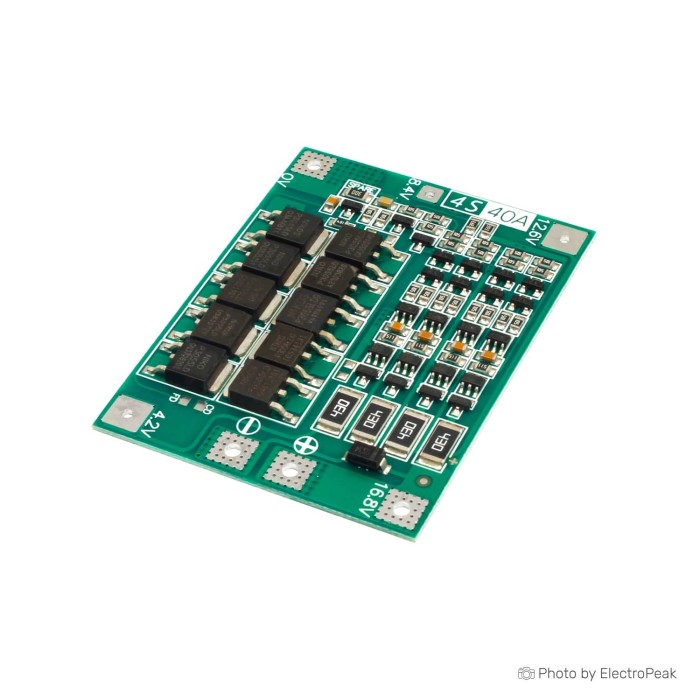
4S 16.8V 40A BMS 18650 Lithium Battery Protection Board
$0.9500
In stock
SKU
BAT-03-070
Volume discounts:
- +50 3 % $0.9200
- +100 5 % $0.9000
- +300 7 % $0.8800
- +500 8 % $0.8700
- +1000 11 % $0.8500
Ships in 2-3 business days, then:
Free delivery in 12-15 days by Tracked Economic Shipping on orders over $100.
Free delivery in 7-10 days by Express Shipping on orders over $300.
More shipping info

Shop with confidence Learn More
 4S 16.8V 20A BMS 18650 Lithium Battery Protection Board Previous
4S 16.8V 40A BMS Review
The 4S 16.8V 40A BMS is a lithium battery protection and balancing board for four-series (4S) lithium-ion or lithium-polymer packs. At 46x60x3.4mm, it includes monitoring circuitry for overcharge, over-discharge, overcurrent, and short-circuit protection. Its 40A working current rating demands active thermal management and careful load verification near that threshold; this is not an uncooled, plug-and-play module.
Custom battery packs for portable power and power-tool rebuilds depend on clean series wiring and low-resistance joins. Durable high-current cell interconnects help the pack maintain conductivity under load. For a different cell count or power profile, browse our battery management system modules for configurations covering alternative voltages and discharge capacities.
Specifications of 4S 16.8V 40A BMS 18650 Lithium Battery Protection Board
- Over charge detection voltage: 4.28+ 0.05 V
- Over charging voltage: 4.095-4.195V
- Charging voltage: 16.8V - 18.1V
- Over discharge voltage: 2.55±0.08
- Over charge detection delay time: 0.1s
- Temperature range: -30-80„
- Short circuit detection delay time: 100ms
- Over current detection delay time: 500 ms
- Balanced current: 60mA
- Working current: 40A
- Over current: 80A
- Short circuit protection function: Yes,disconnect the load can be self recovery
- suitable for electric drills with starting current below 80A and power below 135W
- size: 46x60x3.4mm
4S 40A BMS Current and Thermal Limits
The board specifies a 40A working current and an 80A overcurrent trip threshold with a 500 ms detection delay. In bench builds, continuous loads above roughly 10A to 20A produce noticeable heat across the switching MOSFETs. No heatsink is pre-installed, so sustained high-current loads in sealed battery enclosures need supplemental cooling, heatsinking, or forced airflow to prevent thermal stress and premature shutoff.
Its integrated passive cell balancing operates at a modest 60mA. That balance bleed current keeps healthy, closely matched cells aligned during the final phase of charge; it cannot return severely degraded or mismatched cells to equilibrium. For tool applications, the board is rated for electric drills with a starting current below 80A and total power below 135W. High-torque motors drawing excessive starting current beyond the 80A detection window will trip the protection circuit.
The 46x60x3.4mm footprint also affects enclosure planning, which must leave clearance above the switching devices. If your system consistently draws near or above 40A continuous, use a dedicated board with higher current ratings for safer headroom. The higher-current 4S battery protection board supports discharge capacities up to 100A and provides for external thermal management. Other architectures, including 6S platforms, often place built-in heatsinks directly on the PCB, underscoring the need to plan cooling around compact, uncooled boards.
4S 16.8V 40A BMS Wiring and Charger Compatibility
This protection board is intended strictly for standard 3.6V–3.7V nominal lithium-ion or lithium-polymer chemistries, which reach 4.2V per cell at full charge, or 16.8V for the complete pack. It is not compatible with 3.2V nominal LiFePO4 cells, whose chemistry needs lower overcharge and over-discharge thresholds. For cylindrical-cell packs using 18650 cells for a 4S battery pack, spot-welding with proper nickel strip for battery connections avoids thermal damage to the cell caps compared with direct soldering.
Charging requires an external regulated 16.8V constant-current/constant-voltage (CC/CV) power supply. Although the board listing gives a charging voltage range of 16.8V - 18.1V, a standard 4S Li-ion pack must not be charged from an unregulated supply or set to 18.1V. Doing so relies on the board's emergency overcharge cutoff instead of proper charger termination. Terminate high-current output leads in a reliable connector, such as a high-current battery output connector, to avoid loose-terminal shorts.
| Parameter | Specification / Requirement | Design Consequence |
|---|---|---|
| Pack Topology | 4S (4 series cell groups) | Requires exactly four cell series taps connected in rising sequential potential. |
| Compatible Chemistry | 3.6V–3.7V nominal Li-ion / LiPo | Incompatible with 3.2V LiFePO4 due to mismatched voltage cutoff points. |
| Standard Full Charge | 16.8V | Requires a dedicated 16.8V CC/CV charger; no charging circuitry is built into the board. |
| Working Current | 40A | Requires thermal derating or added heatsinking for continuous high-load duty cycles. |
| Overcurrent Threshold | 80A (500 ms delay) | Absorbs momentary motor inrush; sustained draws over 80A trip output cutoff. |
| Balancing Mechanism | 60mA passive bleed | Equalizes minor cell drift; cannot balance damaged or vastly mismatched capacities. |
| Short Circuit Function | 100 ms detection delay | Protects against external dead shorts; self-recovers once the fault load is disconnected. |
| Dimensions | 46x60x3.4mm | Low-profile footprint suited for power tool handle enclosures and compact project boxes. |
4S 40A BMS Limitations and Common Mistakes
This module is an unbranded generic board produced across multiple revisions, so pad layouts and silkscreen markings can vary. Check every wiring connection against the markings stamped on the received PCB, not an unverified online schematic. Connecting balance leads out of sequence—such as attaching intermediate taps before B- ground—can permanently damage the board's sense circuitry.
Treating the board as a battery charger is another frequent mistake. A BMS is an internal safety disconnect and balancing switch; it contains no buck, boost, or current-limiting circuitry to regulate power from a raw DC transformer. The 60mA passive balance circuit is not a battery-conditioning system either. Where older cells have divergent internal resistance, an external module for additional battery cell balancing can speed equalization across cell groups without replacing the board's core protection functions.
4S 16.8V 40A BMS Accessories and Pack Parts
A dependable 4-cell power pack requires supporting hardware that is not included in the package. A complete assembly combines safety components, structural materials, and accurate diagnostic gear.
- Required Components:
- Four matched 3.6V/3.7V lithium-ion or lithium-polymer cell groups.
- A dedicated 16.8V CC/CV lithium-ion battery charger.
- Spot-weldable pure nickel strip or heavy copper interconnects.
- High-strand silicone wire rated for your continuous output current.
- A digital multimeter to confirm individual tap voltages before soldering.
- Recommended Build Items:
- A durable quick-disconnect plug, such as an XT60 pair, for output lines.
- An inline DC fuse matched to your load envelope and placed close to the pack output.
- Capton tape, barley paper, and high-diameter heat-shrink tubing for electrical insulation.
- An aluminum heatsink and thermal transfer pad for loads above 15A continuous.
- Optional Additions:
- A panel-mounted DC voltmeter or 4S state-of-charge gauge for voltage monitoring.
- An inline temperature probe to monitor cell and MOSFET thermal rise under heavy use.
4S 16.8V 40A BMS First-Power Check
Validate the pack and board sequence before connecting demanding loads to prevent short circuits and component failures. Follow this bench verification sequence:
- Verify Individual Cell Voltages: Measure each cell group independently with a multimeter. Ensure all four groups sit within 0.05V of each other and within a healthy state of charge, from 3.6V to 4.0V per cell.
- Identify Board Terminals: Inspect the silkscreen on your delivered PCB. Confirm the ground pad (typically B-), the intermediate series taps (such as B1, B2, B3), the full-pack positive terminal (typically B+), and the load/charge output pads.
- Wire the Series Taps in Order: Solder the connection leads from the lowest potential, B-, sequentially upward through the intermediate cell taps, finishing at pack positive, B+.
- Check Output Voltage: Measure the potential across the main output pads. It should match the full pack voltage measured across the battery series strings. If zero volts appears, briefly apply a 16.8V charging source to wake the protection IC.
- Conduct a Low-Current Load Test: Connect a low-power 12V–16V resistive load or light bulb. Confirm that voltage remains stable across the pack without triggering cutoff.
- Monitor Thermal Rise: Apply your working load while periodically checking the MOSFET array temperature with an infrared thermometer. If the board surface temperature rises rapidly, reduce the load or add auxiliary heatsinking.
4S 16.8V 40A BMS FAQ and Buying Checklist
Frequently Asked Questions
Is this a BMS for a 4S LiFePO4 battery pack?
No. This board is calibrated exclusively for standard 3.6V–3.7V nominal Li-ion or LiPo cells. LiFePO4 chemistry has a 3.2V nominal voltage and lower full-charge limits of 3.65V per cell, so this board's 4.28V overcharge threshold would dangerously overcharge LiFePO4 cells.
Can the 4S 16.8V 40A BMS deliver 40A continuously?
The board carries a 40A working current rating, but continuous high-current operation above 15A–20A generates considerable heat. Sustained high-current draws require external heatsinks, airflow, and derating to keep the MOSFETs within safe temperature boundaries.
What charger should I use with this 4S 16.8V BMS?
Use a regulated 16.8V CC/CV lithium-ion charger. Do not use an unregulated power adapter or set the charger to the 18.1V upper specification figure, as the charger must govern the charge profile rather than force the BMS into safety cutoffs.
Does this 4S 40A BMS balance the cells?
Yes. It provides passive balancing at 60mA per cell. This bleed current corrects minor drift between healthy cells, but it cannot restore balance to an inherently damaged, weak, or capacity-mismatched pack.
Why might a drill or motor stop after a few seconds?
Motor startup can draw enough inrush current to exceed the 80A overcurrent limit. High initial draw can also make weak cells sag below the 2.55V over-discharge cutoff, causing an immediate protection shutdown.
Do I need a heatsink on this 4S 40A BMS?
No heatsink is provided on the module. For moderate continuous currents above 10A to 20A, add an aluminum heatsink with thermal tape to avoid thermal cutoff.
What is included with the BMS board?
The shipment includes only the bare protection PCB. Wiring harnesses, nickel strips, output connectors, fuses, heatsinks, cells, and chargers are not included and must be sourced separately.
When should I choose the 3S/4S/5S 100A High-Current BMS Board instead?
Choose the 4S BMS for higher-current loads when your motor, inverter, or power pack continuously draws high amperage beyond the safe thermal capacity of an uncooled 40A board.
Purchase Decision Summary
- Suited to: DIY builders constructing compact 4S 18650/LiPo packs for LED arrays, field equipment, portable DC power, or replacement battery packs for small cordless tools operating under 135W and 80A startup.
- Maybe for: Higher-current setups where you have room inside the enclosure to mount heatsinks, monitor thermal performance, and verify that actual current remains well managed.
- Avoid if: You are using 3.2V LiFePO4 cells, need guaranteed plug-and-play 40A continuous draw without adding thermal dissipation, or require a manufacturer-traceable board with factory datasheets. In those situations, consider other battery management system options designed for your specific chemistry and enclosure limits.
Pre-Purchase Verification Checklist
- Battery chemistry is verified as standard 3.6V/3.7V Li-ion or LiPo (not LiFePO4).
- Pack configuration is confirmed as 4S (four series-connected cell strings).
- A regulated 16.8V CC/CV charger is available (charger is not included).
- Continuous load draw is budgeted below the thermal limit, or cooling space is planned.
- Motor or drill startup current stays below the stated 80A overcurrent threshold and 135W limit.
- Enclosure accounts for the 46x60x3.4mm dimensions plus wiring and thermal clearances.
- A multimeter is on hand to confirm wiring order on the received PCB silkscreen before powering.
| Cell Count | 4 |
|---|---|
| Nominal Voltage (V) | 16.8V |
| Max Current (A) | 40A |
| Cell Balancing | Balanced charging |
| Protection | Overcharge,Over-discharge,Overcurrent,Short-circuit |
| Board Dimensions (mm) | 46x60x3.4 |
| Application | Energy storage systems,Electric bikes (e-bikes),High-power electric tools,Lithium battery DIY projects,Portable devices and high-power systems |
| Operating Temp (°C) | -30 to 80 |
| Charging Voltage (Pack) | 16.8V - 18.1V |
Write Your Own Review

Please complete your information below to login.
Sign In
Create New Account