
Product added to cart

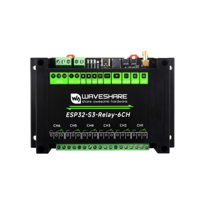
Waveshare Industrial 6-Channel ESP32-S3 WiFi Relay Module
$34.9500
In stock
SKU
MOD-08-001
Volume discounts:
- +10 4 % $33.6000
- +25 6 % $32.9300
- +50 8 % $32.2600
- +100 10 % $31.5900
- +300 12 % $30.9100
Ships in 2-3 business days, then:
Free delivery in 12-15 days by Tracked Economic Shipping on orders over $100.
Free delivery in 7-10 days by Express Shipping on orders over $300.
More shipping info

Shop with confidence Learn More
 CAN 16-Channel Relay Module Previous
Waveshare ESP32-S3-Relay-6CH Review
The Waveshare Industrial 6-Channel ESP32-S3 WiFi Relay Module combines an ESP32-S3 microcontroller with six optocoupler-isolated SPDT relays, isolated RS485, 2.4GHz Wi-Fi, and Bluetooth 5 in a rail-mountable enclosure. It suits developers and automation integrators building custom automation panels, IoT switching, and Modbus-compatible installations, with direct firmware control and I/O expansion through its onboard 40-pin header. This is a programmable controller, not a turnkey appliance: it has no active vendor cloud ecosystem, no 5GHz network support, and no plug-and-play operation out of the box.
For automation integrators comparing relay and switch modules, this board is a programmable controller rather than a closed consumer switch. Detailed hardware documentation is available on the Waveshare product resource page.
Specifications of Waveshare Industrial 6-Channel ESP32-S3 WiFi Relay Module
- Microcontroller: ESP32-S3 (Default module: ESP32-S3-WROOM-1U-N8, customizable for other modules)
- Wireless Communication: 2.4GHz WiFi (802.11 b/g/n), Bluetooth 5, BLE
- USB Connector: USB Type-C for power supply, USB communication, firmware downloading
- Isolated RS485 — Connector: Screw terminal
- Isolated RS485 — Direction Control: Hardware automatic control
- Isolated RS485 — Protection: TVS diode, surge protection, ESD protection
- Isolated RS485 — Resistor: Onboard 120R matching resistor, enabled via jumper
- Expanded Interface: 40-pin header for additional functions like RTC, CAN, RS232, LoRa, sensors
- Relay — Contact Rating: ≤10A 250VAC/30VDC
- Relay — Relay Channels: 6
- Relay — Contact Form: 1NO 1NC
- Relay — Isolation: Optocoupler isolation
- LED Indicators — RGB: Programmable RGB LED
- LED Indicators — PWR: Red power indicator for USB connection and voltage detection
- LED Indicators — TXD: Green TX indicator for RS485 port data transmission
- LED Indicators — RXD: Blue RX indicator for device port data reception
- Power Supply Screw Terminal — Voltage Range: 7~36V
- Dimensions: 145x90x30mm
Before fitting the module into an enclosure, confirm that the physical unit marking matches the ESP32-S3-Relay-6CH specification and inspect the terminal arrangement. The board has six distinct screw-terminal groups for Common (COM), Normally Open (NO), and Normally Closed (NC) contacts. For software builds requiring specific partition schemes or over-the-air (OTA) update memory allocations, inspect the label on the installed ESP32-S3-WROOM-1U module before flashing, as flash capacities may vary between production runs.
Waveshare ESP32-S3-Relay-6CH Specifications Explained
For control-cabinet use, the important question is how the electrical interfaces behave under field conditions. These specifications set the limits for power distribution, switching capacity, and network integration.
| Specification | Hardware Value | Why It Matters |
|---|---|---|
| Relay Contact Rating | ≤10A 250VAC / 30VDC | Indicates maximum resistive load limit per channel. Inductive or inrush loads require significant derating. |
| Contact Form | 6 Channels, 1NO 1NC (SPDT) | Allows wiring circuits in either normally-open or normally-closed configurations to match fail-safe requirements. |
| Terminal Input Voltage | 7~36V DC | Matches standard 12V and 24V industrial control supplies commonly used in automation enclosures. |
| USB Power Input | 5V / 1A via USB Type-C | Allows benchtop programming, testing, and configuration without wiring an external power supply to the screw terminals. |
| Wireless Bands | 2.4GHz Wi-Fi, Bluetooth 5, BLE | Connects to standard 2.4GHz Wi-Fi networks; incompatible with 5GHz-only network infrastructures. |
| Enclosure Dimensions | 145 x 90 x 30 mm | Defines physical cabinet space requirements. Verify clear depth inside low-profile DIN-rail enclosures. |
Each of the six output relays has individual COM, NO, and NC screw terminals. The ≤10A 250VAC/30VDC contact rating defines the upper electrical threshold for resistive switching, but it is not a blanket rating for heavy motor loads, electric heaters, or capacitive LED power supplies that create large initial current surges.
Two power paths simplify setup. The main screw terminal accepts 7~36V DC, so a 12V terminal power option suits standalone enclosure installations when the total current budget covers the board and any attached expansion modules. For bench commissioning, the USB Type-C port supplies 5V at up to 1A and handles data exchange at the same time.
Wireless connectivity is limited to 2.4GHz 802.11 b/g/n and Bluetooth 5. Industrial sites or commercial offices using strict 5GHz-only Wi-Fi networks cannot connect this controller wirelessly without a separate dual-band bridge. The onboard indicators show operating status: the red PWR LED signals power detection and USB connectivity, the green TXD and blue RXD LEDs show serial activity across the RS485 port, and the programmable RGB LED supports custom status signaling in firmware.
Check cabinet clearance before final layout. Although the official specification lists a 30 mm depth, some enclosure documentation references an external depth of up to 40 mm. Measure the internal clearance of your mounting cabinet before final layout assembly. Where only a single low-voltage relay is needed without panel-mounting hardware, the one-relay 5V ESP8266 automation board is a compact single-channel alternative.
Waveshare ESP32-S3-Relay-6CH RS485 and Pico HAT Expansion
Industrial installations often need to bridge wireless telemetry and wired fieldbuses. The onboard isolated RS485 interface uses TVS diodes, surge protection, and ESD clamping to protect the ESP32-S3 from transients induced along long field-wiring runs. Hardware handles direction control, eliminating the need for manual transmit-enable toggling in firmware.
An onboard jumper selects the built-in 120-ohm matching resistor. Do not enable this termination jumper by default: leave it open when the relay board sits in the middle of an RS485 daisy chain, and bridge it only when the unit is a physical endpoint on the transmission line. The serial interface maps internally to ESP32-S3 UART pins GPIO17 (TX) and GPIO18 (RX).
| Signal / Function | ESP32-S3 GPIO Pin | Configuration Notes |
|---|---|---|
| Relay Channel 1 | GPIO1 | Optocoupler-isolated digital output |
| Relay Channel 2 | GPIO2 | Optocoupler-isolated digital output |
| Relay Channel 3 | GPIO41 | Optocoupler-isolated digital output |
| Relay Channel 4 | GPIO42 | Optocoupler-isolated digital output |
| Relay Channel 5 | GPIO45 | Optocoupler-isolated digital output |
| Relay Channel 6 | GPIO46 | Optocoupler-isolated digital output |
| Onboard Buzzer | GPIO21 | Audible alarm / notification output |
| Addressable RGB LED | GPIO38 | Status indicator (WS2812 protocol) |
| RS485 Transmit (TX) | GPIO17 | Hardware-controlled direction |
| RS485 Receive (RX) | GPIO18 | Hardware-controlled direction |
The 40-pin expansion header exposes power rails, serial interfaces, SPI, and I2C buses for add-on modules including real-time clocks (RTC), CAN controllers, RS232 converters, LoRa transceivers, and environmental sensors. It is mechanically arranged to accept Raspberry Pi Pico HATs, but electrical compatibility applies only to select HAT designs. The header breaks out signals from an ESP32-S3 rather than an RP2040 microcontroller, so cross-reference pin functions, logic levels, total current consumption, and enclosure clearance before mounting a HAT. For breadboard signal mapping and bench verification, a low-voltage expansion-header prototyping cable set makes breakout testing easier.
For projects using only wired Modbus RTU switching over serial lines, with no need for wireless control, a dedicated single-channel wired Modbus relay control module provides a direct serial-driven approach without an application microcontroller.
Waveshare ESP32-S3-Relay-6CH Connectivity and Firmware Options
The ESP32-S3 at the center of the board provides native USB connectivity through the USB Type-C port for serial terminal communication and firmware flashing. Several common toolchains are available, depending on your software requirements.
In the Arduino development environment, install the Espressif ESP32 board package, select esp32s3 dev module as the target board, and confirm the correct COM port. Depending on the sketch, USB CDC On Boot may need to be configured in the tools menu to retain serial communication. See our guides to installing the ESP32 board package in Arduino IDE and ESP32 development-board basics for step-by-step toolchain setup.
MicroPython users can deploy firmware through Thonny by flashing the customized MicroPython builds and demonstration scripts supplied by Waveshare. Generic ESP32-S3 MicroPython firmware builds can also be flashed, though board-specific demo scripts and helper libraries require manual pin mapping.
Community ESPHome configurations let this board operate as a local smart-home relay node for Home Assistant. Map the six relay channels to GPIO1, GPIO2, GPIO41, GPIO42, GPIO45, and GPIO46, and map GPIO38 to an addressable light component. Community templates are also available for Tasmota firmware. After initial Tasmota flashing, check RGB colour mapping, as community reports indicate that the red and green channels may need software inversion to display intended colors correctly.
Waveshare previously offered a cloud-control demo, but the Waveshare Cloud service is no longer maintained. Build your deployment around local web control, MQTT brokers, ESPHome, or custom server infrastructure. For simple plug-and-play smartphone-app switching without custom code, the app-controlled single-relay switching module uses the Sinilink platform for scheduled switching through a smartphone app.
Waveshare ESP32-S3-Relay-6CH Installation Limits and Relay Safety
Relay boards used in automation panels need careful load engineering to avoid premature contact failure and electrical hazards. The onboard relays have a stated maximum rating of ≤10A 250VAC or 30VDC under resistive-load conditions.
Inductive loads such as electric motors, solenoid valves, contactor coils, and compressor pumps produce high startup inrush currents and significant back-EMF spikes during disconnection. Switching inductive equipment at or near nominal relay ratings can cause contact arcing, contact welding, or severe electrical noise that resets the microcontroller. For inductive AC loads, use a suitably rated RC snubber or metal-oxide varistor (MOV) across the load contacts and significantly derate continuous operating current. Highly demanding loads should use the onboard relays only as pilots for heavy-duty industrial external contactors.
Carry out mains-voltage wiring only while all circuits are completely de-energized. Fit suitable upstream branch protection, such as fuses or miniature circuit breakers sized for the attached wiring and load. Keep low-voltage sensor lines and RS485 fieldbuses isolated from high-voltage AC conductors inside the enclosure.
Account for these engineering limitations during system design:
- No third-party safety or compliance certifications, such as UL, CE, or UKCA declarations, are documented for this board.
- No official ingress protection (IP) rating is specified; the ventilated ABS plastic casing is intended for dry, indoor control cabinets only.
- Manufacturer documentation does not provide contact electrical switching endurance curves, thermal derating data, or shock/vibration ratings.
- Relay output states are not guaranteed during power brownouts, chip reset cycles, or firmware updates. System firmware must explicitly initialize safe output states at boot.
- Enclosure-depth planning should account for physical variation between the listed 30 mm specification and 40 mm outer housing limits.
- Inspect the metal shield on the ESP32-S3-WROOM-1U module before deploying flash-dependent custom binaries to confirm whether an 8MB (N8) or 16MB (N16) module is fitted.
For panels using 12V DC control power, connect a 12V terminal power option to the 7~36V DC screw terminal. Where an installation must switch a very large array of industrial circuits alongside CAN bus communication, consider high-density multi-interface relay systems built around 16 isolated channels.
ESP32-S3 6-Channel Relay Board Alternatives
Automation architectures vary in channel density, bus protocols, and power-delivery schemes. The alternatives below fit different cabinet and control requirements.
| Product | Channels | Primary Interface | Operating Power | Best Application |
|---|---|---|---|---|
| Waveshare ESP32-S3-Relay-6CH | 6 | 2.4GHz Wi-Fi, BLE, Isolated RS485 | 7~36V DC / 5V USB-C | Multi-channel custom IoT control, ESPHome, and hybrid Wi-Fi/RS485 panels |
| ESP-01S Relay Module (5V DC) | 1 | 2.4GHz Wi-Fi (ESP8266) | 5V DC | Single-point DIY Wi-Fi switching where space is minimal |
| ESP8266 AC Relay Board (85V–264V) | 1 | 2.4GHz Wi-Fi (LAN App) | 85~264V AC | Direct mains-powered local app switching without an external DC power brick |
| 5V WiFi Relay Module (Sinilink App) | 1 | 2.4GHz Wi-Fi (Mobile App) | 5V DC | Consumer appliance control using mobile app scheduling and inching modes |
| 4-Channel Bluetooth Relay Module | 4 | Bluetooth 2.1 / BLE | 12V DC | Short-range wireless switching without connecting to local Wi-Fi networks |
| 2-Channel Modbus RS485/TTL Relay Module | 2 | Wired RS485 / TTL UART | 7~24V DC | Wired PLC or Modbus RTU installations requiring no wireless stack |
| 16-Channel CAN/RS485 Industrial Relay Module | 16 | CAN, RS485, Ethernet, Wi-Fi | 12V / 24V DC | High-density industrial panels managing multiple fieldbuses and dozens of loads |
Where mains power is available at the installation point but no low-voltage DC bus is present, a direct-AC LAN relay control module operates directly from 85V–264V AC. For local phone control within a 10-meter radius without Wi-Fi infrastructure, a short-range Bluetooth relay control board provides multi-channel Bluetooth switching. Strictly hardwired industrial automation is better served by a two-channel wired RS485 relay control module, which provides Modbus RTU communication over twisted-pair lines with low software overhead.
Waveshare ESP32-S3-Relay-6CH Setup, FAQ and Buying Checklist
Test the board in a low-risk environment before mounting it in a panel to avoid common wiring and firmware errors. Follow this initial power and verification sequence:
- Inspect the board for physical transit defects, verify the six terminal blocks, and check the module label on the ESP32-S3 shielding.
- Thread the included external SMA antenna onto the gold connector at the top edge of the board. Never transmit over Wi-Fi or BLE without the antenna fitted.
- Connect a data-capable USB-A to USB-C cable between your computer and the board's USB Type-C port. Do not use charge-only cables.
- Confirm that the red PWR LED illuminates immediately.
- In your chosen development environment, such as Arduino IDE or Thonny, connect to the detected serial port and upload a basic test sketch to toggle one relay channel. Confirm audible relay clicking before wiring high-voltage loads.
- For RS485 communication, wire lines A and B to your bus and install the 120-ohm termination jumper only when this unit sits at the end of the line.
Frequently Asked Questions
Does the Waveshare ESP32-S3-Relay-6CH need a Raspberry Pi?
No. The board operates independently through its built-in ESP32-S3 dual-core microcontroller. Its 40-pin header accepts certain Raspberry Pi Pico expansion HATs, but no external host computer is required to run the module.
Does this ESP32-S3 six-channel relay board work on 5GHz Wi-Fi?
No. It supports 2.4GHz Wi-Fi (802.11 b/g/n) and Bluetooth 5 only, so it cannot connect to 5GHz-only wireless networks.
Can the Waveshare ESP32-S3-Relay-6CH run from 12V or 24V DC?
Yes. The screw-terminal power input accepts 7V to 36V DC, making it compatible with both 12V and 24V control circuits.
Can I power the board through USB-C?
Yes. The USB Type-C port supports 5V power at up to 1A for firmware development, testing, and operation, alongside full USB data communication.
Is the antenna included, and is a USB-C cable included?
The package includes an external 2.4GHz SMA antenna and a small screwdriver. A USB Type-C data cable is not supplied and must be sourced separately.
Can I use this six-channel WiFi relay with ESPHome and Home Assistant?
Yes. Community ESPHome configurations are established for this module by mapping the six relay outputs to GPIO1, GPIO2, GPIO41, GPIO42, GPIO45, and GPIO46. It is not an out-of-the-box Home Assistant appliance and requires user configuration and flashing.
Can this board switch a 230V appliance, pump, motor, or HVAC load?
The contacts are rated up to 250VAC at ≤10A resistive, but inductive loads such as motors, compressors, and pumps create large turn-on surges and back-EMF spikes. These loads require current derating, protective snubber or varistor circuits, and proper enclosure isolation. High-draw appliances should use an external contactor driven by this board.
Why is my RS485 device not communicating?
Check for inverted A and B signal lines, incorrect baud rates, and serial-address mismatches. Confirm that the onboard 120-ohm matching-resistor jumper is installed only when the board is at the physical end of the RS485 bus.
What should I do if firmware upload fails or the serial port disappears?
Put the ESP32-S3 into manual bootloader mode: hold down the BOOT button, press and release the RESET button, then release the BOOT button. Confirm that your USB-C cable supports data transmission and that the proper COM port is selected in your IDE.
Can I use Waveshare Cloud for remote control?
No. The Waveshare Cloud platform is no longer maintained. Use local web interfaces, MQTT brokers, ESPHome, or custom cloud services instead.
Are all Raspberry Pi Pico HATs compatible with the 40-pin header?
No. Compatibility is limited to specific Pico HATs. Verify pin assignments, supply voltages, signal protocols, and physical clearance within the enclosure before fitting an expansion board.
Does this module definitely use ESP32-S3-WROOM-1U-N8 memory?
Website specifications list the default module as the N8 (8MB flash), while some manufacturer documentation references N16 (16MB flash). Inspect the printed label on the installed module to verify flash capacity before flashing custom partition maps.
Purchase Decision Summary
- Ideal for: Automation developers needing six programmable SPDT relay channels with 2.4GHz Wi-Fi, Bluetooth 5, and isolated RS485 in a rail-mountable form factor.
- Maybe for: Home Assistant integrators comfortable flashing and managing custom ESPHome or Tasmota firmware, or engineers building hybrid Modbus/Wi-Fi sensor panels.
- Avoid if: You need out-of-the-box cloud app control, 5GHz Wi-Fi support, built-in Ethernet/PoE, universal Pico HAT compatibility, certified safety-critical control equipment, or direct unbuffered switching of heavy motor loads.
Buying Checklist
- [ ] My project requires up to six independently controlled SPDT (1NO 1NC) relay outputs.
- [ ] My wireless network operates on the 2.4GHz band (802.11 b/g/n).
- [ ] I have an appropriate power supply planned: 7~36V DC for panel terminals or 5V/1A via USB-C.
- [ ] I have a data-capable USB Type-C cable available for firmware flashing and testing.
- [ ] I have space to mount the external SMA antenna outside metal enclosures if needed.
- [ ] My planned cabinet depth accommodates dimensions of 145 x 90 x 30 mm (or up to 40 mm outer profile).
- [ ] I have evaluated load inrush currents and planned appropriate fuses, RC snubbers, or external contactors for inductive equipment.
- [ ] I am prepared to flash and configure custom firmware (Arduino, ESPHome, MicroPython) rather than relying on a vendor cloud app.
- [ ] If using RS485, I understand when to engage the onboard 120-ohm termination jumper based on bus topology.
- [ ] I will check the physical ESP32-S3 module label upon delivery to confirm flash capacity prior to building custom partitions.
Write Your Own Review

Please complete your information below to login.
Sign In
Create New Account