Product added to cart

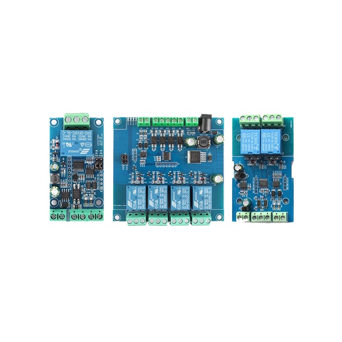
TTL/RS485 4-Channel Relay Module
$5.5000
In stock
SKU
MOD-08-005
Volume discounts:
- +25 4 % $5.2900
- +50 6 % $5.1800
- +100 8 % $5.0700
- +300 10 % $4.9700
- +500 12 % $4.8600
Ships in 2-3 business days, then:
Free delivery in10-15 days by YunExpress on orders over $35.
Free delivery in5-7 days by DHL on orders over $200.
More shipping info

Shop with confidence Learn More
 Waveshare Industrial 6-Channel ESP32-S3 WiFi Relay Module Previous
The TTL/RS485 4-Channel Relay Module is a versatile and reliable relay module designed for various applications requiring robust communication protocols and high-efficiency performance. Equipped with an onboard 8-bit MCU and MAX485 level conversion chip, this module supports standard Modbus RTU protocol and offers communication interfaces through RS485 and TTL UART. It operates at a default baud rate of 9600bps and can be adjusted to 4800 or 19200bps, with settings retained after power-off. The module supports a wide input signal range and offers multiple relay output modes, ensuring flexible and efficient operation.
Specifications of TTL/RS485 4-Channel Relay Module
-
MCU: 8-bit onboard MCU
-
Level Conversion Chip: MAX485
-
Communication Protocol: Modbus RTU
-
Communication Interface: RS485/TTL UART
-
Communication Baud Rate: 4800/9600/19200 (default 9600bps)
-
Optocoupler Input Signal Range: DC 3.3-30V
-
Output Signal: Relay switch signal (manual, flash-off, flash-on modes)
-
Device Address Range: 1-255 (default 255)
-
Relay Specifications: 5V, 10A/250V AC, 10A/30V DC
-
Relay Activation Life: 100,000 times
-
Protection: Diode overflow protection
-
Indicators: Onboard relay switch indicator light
-
Power Supply Voltage: DC 7-24V (with input anti-reverse protection)
-
Dimensions: LxWxH mm (Dimensions: ---)
Modbus RTU Instruction Introduction
The Modbus device receives data from an external control terminal (e.g., host computer/MCU) to execute operations. A frame instruction consists of the device address, function code, register address, register data, and a CRC check code. The first byte is the device address (1-255, default 255 or 0xFF), and the last two bytes are the CRC check code.
Assuming the device address is 255, common Modbus RTU instructions are:
-
Turn on relay No. 1 (manual mode)
-
Send: FF 05 00 00 FF 00 99 E4
-
Return: FF 05 00 00 FF 00 99 E4
-
Remarks: The 3-4 bytes represent the relay address, and the 5-6 bytes represent data (0xFF00 for on, 0x0000 for off).
-
-
Close relay No. 1 (manual mode)
-
Send: FF 05 00 00 00 00 D8 14
-
Return: FF 05 00 00 00 00 D8 14
-
-
Turn on relay No. 2 (manual mode)
-
Send: FF 05 00 01 FF 00 C8 24
-
Return: FF 05 00 01 FF 00 C8 24
-
-
Close relay No. 2 (manual mode)
-
Send: FF 05 00 01 00 00 89 D4
-
Return: FF 05 00 01 00 00 89 D4
-
-
Turn on all relays
-
Send: FF 0F 00 00 00 08 01 FF 30 1D
-
Return: FF 0F 00 00 00 08 41 D3
-
-
Close all relays
-
Send: FF 0F 00 00 00 08 01 00 70 5D
-
Return: FF 0F 00 00 00 08 41 D3
-
-
Set the device address to 1
-
Send: 00 10 00 00 00 01 02 00 01 6A 00
-
Return: 00 10 00 00 00 01 02 00 01 6A 00
-
-
Set the device address to 255
-
Send: 00 10 00 00 00 01 02 00 FF EB 80
-
Return: 00 10 00 00 00 01 02 00 FF EB 80
-
-
Read the device address
-
Send: 00 03 00 00 00 01 85 DB
-
Return: 00 03 02 00 FF C5 C4
-
-
Read relay status
-
Send: FF 01 00 00 00 08 28 12
-
Return: FF 01 01 01 A1 A0
-
-
Read the optocoupler input status
-
Send: FF 02 00 00 00 08 6C 12
-
Return: FF 02 01 01 51 A0
-
-
Set the baud rate to 4800
-
Send: FF 10 03 E9 00 01 02 00 02 4A 0C
-
Return: FF 10 03 E9 00 01 C5 A7
-
-
Set the baud rate to 9600
-
Send: FF 10 03 E9 00 01 02 00 03 8B CC
-
Return: FF 10 03 E9 00 01 C5 A7
-
-
Set the baud rate to 19200
-
Send: FF 10 03 E9 00 01 02 00 04 CA 0E
-
Return: FF 10 03 E9 00 01 C5 A7
-
-
Read baud rate
-
Send: FF 03 03 E8 00 01 11 A4
-
Return: FF 03 02 00 04 90 53
-
-
Open relay No. 1 (flash mode 2S)
-
Send: FF 10 00 03 00 02 04 00 04 00 14 C5 9F
-
Return: FF 10 00 03 00 02 A4 16
-
-
Close relay No. 1 (flash mode 3S)
-
Send: FF 10 00 03 00 02 04 00 02 00 1E A5 99
-
Return: FF 10 00 03 00 02 A4 16
-
Simple Instructions for Use
-
Connect VCC and GND to the power supply's positive and negative poles respectively.
-
Connect A+ and B- to the output end of the USB to RS485 module.
-
Open the host computer software "Modbus RTU Configuration Tool", select the correct port number and set the baud rate to 9600. Set the address to 255, and click "Open Serial Port".
-
Click "JD1 Open" to turn on relay 1, and the indicator light of relay 1 will light up.
Generating CRC Check Code
Modbus RTU commands can be sent using ready-made host computer software (e.g., Modbus RTU configuration tool) that automatically generates the CRC check code. To manually generate a CRC check code for testing using serial port debugging software (e.g., SSCOM):
-
The sending frame composition for turning on/off the relay (manual mode) is: Device address (1Byte) + function code (1Byte) + register address (2Byte) + register data (2Byte) + CRC check code (2Byte)
-
Assuming the device address is 0xFF, the first 6 bytes of the sent frame are: FF 05 00 00 FF 00
-
Use a CRC check tool to find the check code for these 6 bytes: CRC Check Tool
-
Exchange the high and low byte positions of the check calculation result E499 to get the CRC check code 99E4. The complete send frame is: FF 05 00 00 FF 00 99 E4
Send the frame to the Modbus relay module through the serial port debugging software SSCOMV5.13.1
Write Your Own Review

Please complete your information below to login.
Sign In
Create New Account