
Product added to cart

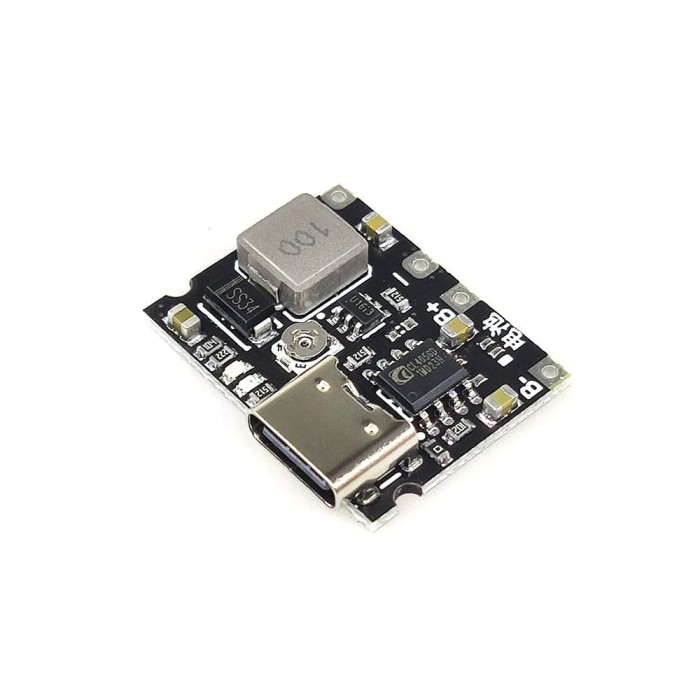
TP4056 18650 Li-ion USB Type-C Battery Charger/Discharger Module - With Boost Converter
$0.6500
In stock
SKU
BAT-16-006
Volume discounts:
- +50 5 % $0.6200
- +100 6 % $0.6100
- +300 8 % $0.6000
- +500 11 % $0.5800
- +1000 12 % $0.5700
Ships in 2-3 business days, then:
Free delivery in 12-15 days by Tracked Economic Shipping on orders over $100.
Free delivery in 7-10 days by Express Shipping on orders over $300.
More shipping info

Shop with confidence Learn More
 Wemos D1 mini Battery Shield Previous
TP4056 Type-C Module With Boost: What It Does and Who It Suits
This compact circuit board combines single-cell lithium battery charging with an onboard step-up DC-DC converter. It charges one 3.7V lithium cell up to 4.2V from a standard 5V USB Type-C supply, then boosts the battery voltage to an adjustable 4.2V–28V output rail. It suits DIY electronics builders prototyping low-draw portable sensors or microcontrollers that need charging and voltage conversion in one small footprint. The board does not include an 18650 cell, does not provide continuous passthrough power for always-on devices, and is not designed for high-current loads.
Compare dedicated chargers and multi-rail regulators in our charging modules and power-management boards category. For projects that do not use direct-soldered battery tabs, pair this module with an external 18650 battery holder for clean, secure cell replacement.
TP4056 18650 Charger Module Specifications
Specifications of TP4056 18650 Li-ion USB Type-C Battery Charger/Discharger Module - With Boost Converter
- Working temperature: -40-80°C
- Input voltage range: 4.2V~6.5V
- Output voltage: 4.2V-28V adjustable
- Maximum power: 5W
- Maximum 1A programmable linear charge current
- For single cell 3.7V lithium battery, fully charged 4.2V
- Constant current/constant voltage charging with over-temperature protection
- Soft start limits surge current, with battery reverse connection protection
- Low power consumption standby to extend battery life
- Dual output of charging status, no battery and fault status
- Display, OV activated, 2.9V trickle charging
TP4056 Type-C Module Specifications Explained
The stated ratings determine how the board handles power budgeting, battery selection, and load connection. Distinguishing the charging-input limits from boosted-output capacity helps prevent unexpected resets or thermal throttling.
| Specification | Stated Value | Why It Matters |
|---|---|---|
| Output Voltage | 4.2V-28V adjustable | The boost stage accommodates diverse logic rails, relays, or operational amplifiers. Because output voltage is controlled by a multi-turn trimmer, you must calibrate it with a meter before connecting sensitive electronics. |
| Maximum Power | 5W | This is the total wattage limit for the boost circuit. As configured output voltage increases, the maximum deliverable current decreases proportionally to remain within this 5W ceiling. |
| Linear Charge Current | Maximum 1A programmable | This rating applies strictly to the constant-current phase of charging the battery from the USB input. It does not indicate available output current to your project load. |
| Battery Compatibility | Single cell 3.7V (4.2V full) | The charging circuit uses standard lithium-ion/lithium-polymer termination parameters. It cannot charge multi-cell series packs or non-lithium chemistries. |
| Input Voltage Range | 4.2V~6.5V | Allows operation from standard 5V USB Type-C power sources while accommodating minor line drops or unregulated 5V DC adapters. |
Need a set rail without manual potentiometer adjustment? A module with a fixed 9V battery boost output removes the need for pre-installation multimeter calibration.
TP4056 Boost Output Limits and Passthrough Caveats
The main design boundary is the 5W maximum power limit. At a 5V output, 5W allows approximately 1A of load current under ideal conditions. Raising the output to 12V reduces available continuous current to roughly 0.4A, while 24V limits usable current to around 0.2A. Inductive loads such as motors or large unbuffered LED arrays can pull the rail down and cause voltage brownouts.
This module is not intended for continuous passthrough operation. In a standard TP4056 linear charging design, the IC monitors battery current to detect when charging drops to the termination threshold, typically C/10. An active circuit connected across the output while charging draws continuous current from the rail. That confuses the charge-termination logic, keeping the charger in continuous constant-current or constant-voltage mode. The result is sustained heat that can shorten cell lifespan.
Linear charging generates heat by dropping input-to-battery voltage across the silicon. At the full 1A charge rate, the board warms noticeably, and unventilated enclosures can trigger the built-in thermal reduction circuitry. Component choices vary across generic TP4056 production runs; specific boost IC models, USB-C configuration resistor setups, and exact under-voltage trip thresholds are not documented for this board. For hardware that must run continuously while plugged in, use a dedicated load-sharing 5V power-bank-style module. Power this board from a standard USB supply with a basic USB Type-C charging cable.
TP4056 Type-C Module Setup and First Power Test
Use this initial bench-verification procedure to configure the board safely before wiring it into a microcontroller project or permanent enclosure.
- Identify the PCB terminals: Check the silkscreen on your board for the battery solder pads, marked B+ and B-, the DC output solder pads, marked VOUT+ and VOUT-, and the status indicator LEDs.
- Connect the battery: Wire a single-cell 3.7V lithium battery, such as a compatible 18650 cell. For clean prototyping without direct soldering to battery terminals, secure the cell in a standard wired 18650 battery holder or a breadboard-compatible DIP 18650 holder. Double-check polarity before soldering.
- Adjust output voltage: Before attaching the target load, connect a multimeter set to DC voltage across VOUT+ and VOUT-. Use a small screwdriver to turn the brass screw on the blue potentiometer until the multimeter reads the required project voltage.
- Verify charging operation: Connect a standard 5V supply with a USB Type-C power cable. Confirm that the charging indicator lights. When no cell is attached or a fault occurs, observe the secondary indicator pattern to verify normal response.
- Attach the load: Solder the downstream device leads directly to VOUT+ and VOUT-. Never connect the project load in parallel across B+ and B- when you need a stepped-up voltage.
- Check for reversed battery leads.
- Do not connect sensitive 3.3V or 5V logic before trimming the factory output voltage down.
- Keep loads within the 5W limit.
- If the board does not charge, check whether the USB-C source is an advanced Power Delivery unit that requires configuration channel (CC) handshaking; standard 5V USB-A to USB-C cables provide the most consistent input connection on generic modules.
If your build needs an integrated cell slot with multiple regulated lines instead of a bare board, evaluate a holder-based 18650 power board.
TP4056 With Boost vs TP4056 Charger-Only and IP5306 Modules
Use the differences below to match the power-management topology to your project's voltage and current demands.
| Module | Charging Method | Output Format | Maximum Output Rating | Key Use Case |
|---|---|---|---|---|
| TP4056 With Boost (This Board) | 1A Linear (USB Type-C) | 4.2V–28V adjustable | 5W total power | Low-power electronics needing a non-standard or stepped-up voltage rail from one cell. |
| charger-only TP4056 board | 1A Linear (Mini, Micro, or Type-C) | Battery voltage direct (no boost) | Limited by cell / pass-through | Dedicated single-cell charging where downstream circuits run on raw battery voltage or separate regulators. |
| 18650 9V Boost Charger Module | Linear charging | 9V fixed | 0.8A max at 9V | Projects requiring a dedicated, pre-set 9V rail without needing potentiometer calibration. |
| IP5306 5V 2A Boost Charger | 2.1A Switch-mode | 5V fixed | 2.4A discharge | Higher-current 5V USB devices needing simultaneous charging and discharging support. |
TP4056 Type-C Module FAQ and Buying Checklist
Does the TP4056 Type-C module include an 18650 battery?
No. This is a bare circuit board that charges and boosts a separate cell. You must supply your own 3.7V lithium-ion or 18650 battery.
Can this TP4056 boost module power a device while the battery is charging?
It is not intended for continuous passthrough operation. Continuous current drawn from the output while the battery charges prevents the TP4056 from detecting current drop-off, disrupting normal charge termination and increasing operating temperatures.
Is the output fixed at 5V?
No. The onboard potentiometer adjusts the output between 4.2V and 28V. Verify and set the voltage with a multimeter before connecting your device.
What does the 5W maximum-power rating mean?
Your connected load must not draw more than 5 watts in total. Higher output voltages reduce available current: at 5V, maximum output is roughly 1A, while at 12V it is limited to roughly 0.41A.
Does the 1A specification mean the module supplies 1A to my project?
No. The 1A specification refers only to the maximum linear charging current delivered into the battery. Output current to your project is governed entirely by the 5W boost-stage capacity.
What battery can I use with this TP4056 Type-C charger module?
Use a single 3.7V lithium-ion or lithium-polymer cell that charges to 4.2V. Do not connect multi-cell battery packs wired in series.
Why is a multimeter recommended for this module?
The boost circuit ships uncalibrated and can output up to 28V out of the box. Measuring the terminals with a multimeter helps ensure you do not inadvertently deliver excessive voltage to low-voltage components.
What should I check if USB Type-C charging does not start?
Check battery connection polarity, confirm that the battery is not already fully charged or deeply discharged below recovery threshold, and try a standard USB-A to USB-C cable. Sophisticated USB-C chargers may not activate without specific configuration channel detection circuitry on the board.
Purchase Decision Summary
- Ideal for: Hobbyists building low-power battery prototypes, small ESP8266 or sensor nodes, and adjustable DC power feeds drawing less than 5W total.
- Maybe for: Enclosed handheld gadgets, provided the enclosure has sufficient passive ventilation for linear-charging heat dissipation.
- Avoid if: You require an all-in-one power bank, high-current 5V rails, simultaneous load-sharing during charge, or an integrated battery slot. For built-in cell mounting and multiple fixed rails, look at a holder-based 18650 power board.
Pre-Purchase Verification Checklist
- I have a separate single-cell 3.7V lithium battery, such as an 18650, rated for 4.2V charging.
- I have an 18650 cell holder or a reliable method to connect battery leads without overheating the cell.
- I have a multimeter available to measure and adjust the boost output before connecting my load.
- My target circuit consumes less than 5W of total power at its target operating voltage.
- My design does not require continuous passthrough power while plugged into the charger.
- I have a standard 5V USB Type-C power source and cable ready for charging.
| Compatible With | 18650 |
|---|---|
| Chipset | TP4056 |
| Function | Battery Charger |
| Charging Voltage (Pack) | 4.2V |
| Supported Battery Type | Li-ion |
| Cell Count | 1 |
| Input Voltage (V) | 4.2V to 6.5V |
| Output Voltage (V) | Adjustable |
| Output Current (A) | 2A |
| Connector | USB Type-C |
| Max Charging Current | 1A programmable |
| Fast Charge Protocol | No |
| USB Connector | USB Type-C |
| Protection | Overcharge,Over-discharge,Short circuit,Battery reverse connection,Over-temperature |
| Display Type | LED |
| Indicator LEDs | Charge status,Battery absent,Fault detection |
| Operating Temp (°C) | -40°C to +80°C |
Write Your Own Review

Please complete your information below to login.
Sign In
Create New Account